

TSI Incorporated 8372, 8373, ACCUBALANCE Plus 8372, ACCUBALANCE Plus 8373 Operation And Service Manual

Ventilation Testing/Balancin
g
Model 8372/73
A
CCUBALANCE
Air Capture Hood
Operation and Service Manual
®
Plus
1980336, Revision C
October 2002


A
CCUBALANCE
Air Capture Hood
Operation and Service Manual
U.S.
Sales and Customer Service:
1-(800) 874-2811 USA/
001-(651) 490-2811
Fax:
001-(651) 490-3824
Model 8372/73
®
Plus
1980336, Revision C
October 2002
MAIL TO:
TSI Incorporated
500 Cardigan Road
Shoreview, MN 55126-3996
USA
E-mail address:
answers@tsi.com
Website:
http://www.tsi.com


Copyright
TSI Incorporated / October 2002 / All rights reserved.
Address
TSI Incorporated / 500 Cardigan Road / Shoreview, MN 55126 / USA
Fax No.
(651) 490-3824
LIMITATION OF WARRANTY AND LIABILITY (effective July 2000)
Seller warrants the goods sold hereunder, under normal use and service as described in the
operator's manual, shall be free from defects in workmanship and material for twenty-four (24)
months, or the length of time specified in the operator's manual, from the date of shipment to the
customer. This warranty period is inclusive of any statutory warranty. T his limited warranty is
subject to the following exclusions:
a. Hot-wire or hot-film sensors used with research anemometers, and certain other
components when indicated in specifications, are warranted for 90 days from the date of
shipment.
b. Parts repaired or replaced as a result of repair services are warranted to be free from
defects in workmanship and material, under normal use, for 90 days from the date of
shipment.
c. Seller does not provide any warranty on finished goods manufactured by others or on any
fuses, batteries or other consumable materials. Only the original manufacturer's warranty
applies.
d. Unless specifically authorized in a separate writing by Seller, Seller m a kes no warranty
with respect to, and shall have no liability in connection with, goods which are
incorporated into other products or equipment, or which are modified by any person other
than Seller.
The foregoing is IN LIEU OF all other warranties and is subject to the LIMITATIONS stated
herein. NO OTHER EXPRESS OR IMPLIED WARRANTY OF FITNESS FOR
PARTICULAR PURPOSE OR MERCHANTABILITY IS MADE.
TO THE EXTENT PERMITTED BY LAW, THE EXCLUSIVE REMEDY OF THE USER OR
BUYER, AND THE LIMIT OF SELLER'S LIABILITY FOR ANY AND ALL LOSSES,
INJURIES, OR DAMAGES CONCERNING THE GOODS (INCLUDING CLAIMS BASED
ON CONTRACT, NEGLIGENCE, TORT, STRICT LIABILITY OR OTHERWISE) SHALL
BE THE RETURN OF GOODS TO SELLER AND THE REFUND OF THE PURCHASE
PRICE, OR, AT THE OPTION OF SELLER, THE REPAIR OR REPLACEMENT OF THE
GOODS. IN NO EVENT SHALL SELLER BE LIABLE FOR ANY SPECIAL,
CONSEQUENTIAL OR INCIDENTAL DAMAGES. SELLER SHALL NOT BE
RESPONSIBLE FOR INSTALLATION, DISMANTLING OR REINSTALLATION COSTS
OR CHARGES. No Action, regardless of form, may be brought against Seller more than 12
months after a cause of action has accrued. The goods returned under warranty to Seller's
factory shall be at Buyer's risk of loss, and will be returned, if at all, at Seller's risk of loss.
Buyer and all users are deemed to have accepted this LIMITATION OF WARRANTY AND
LIABILITY, which contains the complete and exclusive limited warranty of Seller. This
LIMITATION OF WARRANTY AND LIABILITY may not be amended, modified or its terms
waived, except by writing signed by an Officer of Seller.
Service Policy
Knowing that inoperative or defective instruments are as detrimental to TSI as they are to our
customers, our service policy is designed to give prompt attention to any pr oblems. If any
malfunction is discovered, please contact your nearest sales office or representative, or call TSI's
Customer Service department at (651) 490-2811 or ( 800) 874-2811
.


CONTENTS
ABOUT THIS MANUAL .............................................................III
INTRODUCTION ........................................................................IV
Chapters
1. SET UP..................................................................................1
Unpacking..............................................................................1
Parts Identification.................................................................3
Display...................................................................................3
Display Units..........................................................................5
Keypad ..................................................................................5
Changing the Real-Time Clock .............................................6
Compliance Statement for Y2K.............................................7
Changing the Baud Rate....................................................... 7
Preparing the Instrument for Use..........................................7
Installing the Batteries.....................................................7
Hood Assembly...............................................................8
Basic Operation.....................................................................9
Start-Up...........................................................................9
Selecting Flow Direction ................................................. 9
Taking a Flow Measurement ........................................10
Turning the A
Automatic Shut-off ........................................................11
2. OPERATIONS IN MORE DETAIL......................................13
Keypad Functions................................................................13
Field Calibration - Model 8372 Only....................................24
Additional Keypad Functions for the Model 8373 ...............24
Field Calibration - Model 8373 Only....................................25
Changing Hoods..................................................................26
Changing DIP Switch Settings ............................................30
Switch Number....................................................................31
Connecting the Optional Printer..........................................31
Connecting to a Computer ..................................................33
Downloading Data to a Computer.......................................33
Data Acquisition (Polling)....................................................33
CCUBALANCE Plus Off ..............................10
3. MAINTENANCE..................................................................35
Fabric Hood.........................................................................35
Meter ...................................................................................36
Manifold...............................................................................36
Cases ..................................................................................36
Calibration ...........................................................................36

4. TROUBLESHOOTING........................................................37
Appendixes
A. BACK PRESSURE .............................................................41
B. SPECIFICATIONS...............................................................43
ii

About this manual
This manual explains how to set up, operate and maintain the
Model 8372/8373 A
thoroughly before using the instrument.
Formatting and Typography
Note that step-by-step instructions are numbered in boldface type: 1, 2, 3,
etc., set flush-left against the margin.
References to the front panel keys on the A
the instrument's displayed readout, are represented in this manual by the
typeface called Arial Narrow. In addition to the different typeface, displayed
messages appear in quotes.
When reference is made to other sections of the manual, the section title is
italicized.
Example: The “SAMPLE” message will appear along with a flow value after
you have activated the SAMPLE key (from Display in Chapter 1).
HELP!
If you need technical assistance with this instrument, have questions about
the manual, or your air capture hood needs repair or recalibration please call
TSI's Environmental Measurements and Control Division at (651) 490-2811
or (800) 874-2811. Product application notes are designed to provide more
information on the product to the user. Application notes, as well as other
related material, can be obtained by calling TSI or by visiting the TSI web
site at http://www.tsi.com.
CCUBALANCE® Plus Air Capture Hood. Read it
CCUBALANCE Plus, along with

Introduction
The TSI Models 8372/8373 A
to measure the air flow from diffusers and grilles or the air flow entering
exhaust outlets. The A
The instrument can display the measured air flow in four different units:
standard cubic feet per minute (SCFM), standard liters per second (Std l/s),
standard cubic meters per hour (Std m
minute (Std m
3
/min). All readings may also be displayed in actual flow
conditions.
CCUBALANCE Plus consists of a fabric hood, a molded plastic base
The A
which contains an electronic meter, and a flow sensing manifold located
within the base. Air flowing through the hood is measured by a hot-film
sensor located in the central hub of the flow sensing manifold. The twentyfour pairs of flow sensing ports in the manifold are strategically located so
that the A
CCUBALANCE Plus provides the highest degree of measurement
accuracy, even in non-uniform flow conditions.
CCUBALANCE Plus is temperature-compensated to display a standard
The A
flow rate: SCFM, Std l/s, Std m
defined as the volumetric flow rate at standard conditions of 70°F (21.1°C)
and 14.7 pounds per square inch (760 mmHg) barometric pressure.
Standard flow rate is the measurement used most often in ventilation
applications.
CCUBALANCE® Plus are instruments designed
CCUBALANCE Plus is lightweight and easy to use.
3
/hr), and standard cubic meters per
3
/hr, and Std m3/min. Standard flow rate is
iv
Chapter 1
Set Up
This chapter guides you through unpacking, setting up, and getting started
using your A
all operating features.
CCUBALANCE Plus. See Chapter 2 for a detailed description of
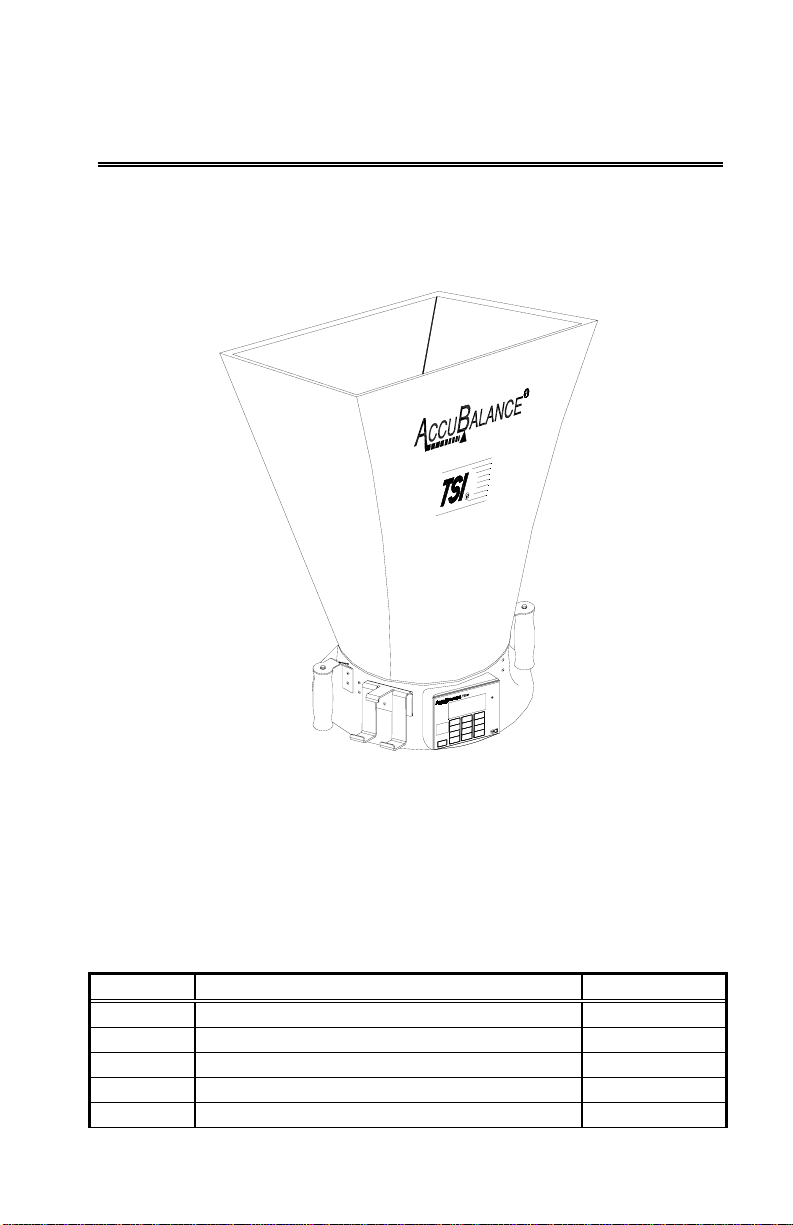
Figure 1: The A
Unpacking
Carefully unpack the instrument and accessories from the carrying case.
Check the individual parts against the list of components in Tables 1 through
3. If any are missing or damaged, notify TSI immediately.
Table 1 List of components
Qty Item Part No.
1 Model 8372/8373 base N/A
1 2 ft x 2 ft (610 mm x 610 mm) hood fabric 1307060
6 Frame support poles 1081390
4 2 ft (610 mm) frame tubing* 1081262
6 Right angle tubing connectors* 1081584
CCUBALANCE Plus
1
Qty Item Part No.
1 Battery holder 1081279
4 C-size batteries 1208018
1 Battery compartment cover 1081458
1 Carrying case 1319067
1 Operation and Service Manual 1980336
1 Data download RS232 cable 1082798
3 3½” floppies containing the “Logdat” data
800832
download software
*Four of the 2 ft frame tubings and four of the right angle connectors are
shipped assembled inside the top of the hood fabric.
Table 2 List of components: -3 Hood Kit (adds 2 hoods to the
base kit)
Qty Item Part No.
1 2 ft x 4 ft (610 mm x 1220 mm) hood fabric 1801065
1 1 ft x 4 ft (305 mm x 1220 mm) hood fabric 1801066
6 2 ft (610 mm) frame tubing 1081262
4 1 ft (305 mm) frame tubing 1081260
6 Right angle tubing connectors 1081584
6 Straight tubing connectors 1302833
Table 3 List of components: -5 Hood Kit (adds 4 hoods to the
base kit)
Qty Item Part No.
1 2 ft x 4 ft (610 mm x 1220 mm) hood fabric 1801065
1 1 ft x 4 ft (305 mm x 1220 mm) hood fabric 1801066
1 1 ft x 5 ft (305 mm x 1525 mm) hood fabric 1801067
1 3 ft x 3 ft (915 mm x 915 mm) hood fabric 1801068
6 2 ft (610 mm) frame tubing 1081262
4 1 ft (305 mm) frame tubing 1081260
6 Right angle tubing connectors 1081584
6 Straight tubing connectors 1302833
2 1x tube connectors 1081580
Included with this product is a registration card. Please complete and mail it
promptly; it allows TSI to inform you of product updates. You may also
register on line by visiting the TSI web site.
2 Chapter 1
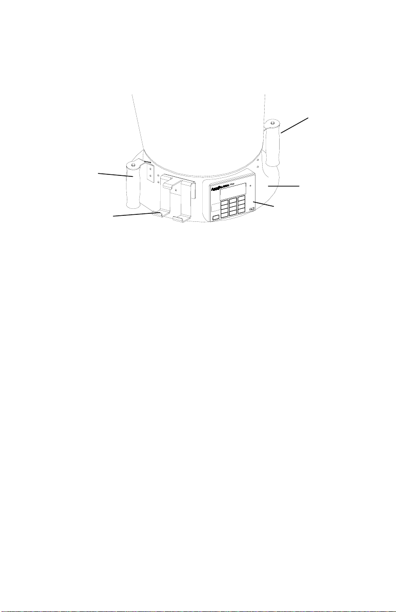
Parts Identification
Before proceeding with assembly and use of the A
CCUBALANCE Plus, please
familiarize yourself with the various parts of the instrument. Refer to
Tables 1 through 3 for part descriptions and Figure 2 for general location of
major items.
2
1
6
3
4
5
Figure 2: A
CCUBALANCE components
1 Fabric hood - Basic hood assembly is covered later in this chapter,
other hoods are discussed in Chapter 2.
2 Right handle with SAMPLE key - used for capturing information on the
display.
3 Meter base
4 Electronic meter and display - Detailed keypad functions are covered
in Chapter 2.
5 Printer bracket - Allows the Model 8925 to be attached to the
CCUBALANCE base for ease of use and recording of data.
A
6 Left handle with PRINT button - Used to print that which is on the
display value to the portable printer.
Display
Each time the A
CCUBALANCE is turned on, all segments of the display will
be shown momentarily. Below is a list of items that will appear on the
display and their use.
Set Up 3

5 9
3
2
Figure 3: Display of the Model 8372/8373
1 Flow units: CFM (cubic feet per minute), l/s (liters per second), m
(cubic meters per hour), and m
CCUBALANCE indicates flow already corrected to "standard"
A
3
/min (cubic meters per minute). The
conditions. Actual flow conditions can be shown by pressing the
ACTUAL/STANDARD key (see Chapter 2 for more detail operation).
2 Flow value: Large digits. See specifications for range and resolution.
3 Message area: Small digits. Simultaneous temperature measurement.
4 Flow direction arrows: Indicates if supply or return air flow
calibration is being utilized by the A
CCUBALANCE.
Notice: For Model 8372 - Be sure this arrow points in the direction of flow
through the ACCUBALANCE Plus, otherwise the measurements made
will be inaccurate. To change the direction of the arrow, press the
SUPPLY/RETURN key. (The Model 8373 senses direction
automatically)
5 ”SAMPLE” will appear every time you press the SAMPLE key or the
button on the top of the right handle.
3
8
4
1
6,7
/hr
6 “%
“ will appear along with a value on the display during power-
up to indicate the percent of battery life remaining.
7 The
symbol will flash when the batteries have only about 10%
life remaining. When the battery is too low for accurate measurements
“LO
“ is displayed momentarily before the instrument is
automatically turned off.
4 Chapter 1

8 “STD” or “ACTUAL” will be displayed at all times. “STD” refers to
readings that are based on standard conditions of 29.92 in. Hg (760
mm Hg) and 70 °F (21.1 °C). “ACTUAL” refers to readings that are
converted to local conditions based on temperature and barometric
pressure.
9 “K
”: K factor symbol to indicate that the readings have an adjustment
f
factored in.
10 “TOTAL”, “MIN”, “MAX”, “AVG”, “COUNT” will be displayed when viewing
STATISTICS.
11 “TEST ID”, “BRANCH”, “TERMINAL” will be displayed when viewing data
for a SAMPLE or when reviewing data.
Display Units
CCUBALANCE Plus is shipped with cubic feet per minute (CFM) as the
The A
default flow unit, °F for temperature, and in. Hg (inches of mercury) for
barometric pressure (unless the metric version was ordered). If you wish to
change the units to l/s (liters per second), m
3
m
/min (cubic meters per minute), °C for temperature, and mm Hg
3
/hr (cubic meters per hour),
(millimeters of mercury) for barometric pressure, see Changing DIP Switch
Settings in Chapter 2. Please note that no units will be shown on the display
for barometric pressure.
Keypad
Below is a drawing of the key pads, Figure 4, for the Model 8372, Figure 5,
for the Model 8373. The keys are referenced in the Basic Operation section
of this chapter and in Chapter 2 - Operations in More Detail.
Set Up 5

Figure 4: Keypad for the Model 8372
Figure 5: Keypad for the Model 8373
Changing the Real-Time Clock
CCUBALANCE Plus has an internal real-time clock that keeps track of
The A
the time of day (the format is HH.MM where HH is the hour in 24-hour
format and MM is minutes) and the date. It is very important to set the time
and date correctly, otherwise date and time stamping of recorded data will
not be correct. This information has been set to Central Time (GMT - 6
hours) (Standard or Daylight Savings) at the factory before shipping. The
CCUBALANCE Plus does not self-adjust for Daylight Savings Time.
A
6 Chapter 1

To change the time and date, press and hold either the ▲ or ▼ key during
the power-up sequence when the time is displayed. Release the keys when
CCUBALANCE Plus beeps twice. You will have an opportunity to view
the A
and/or change the hours, minutes, year, month, and day of month in
sequence. Use the up and down arrow keys (▲▼) to change any settings.
Use the ENTER key to store each setting and advance to the next one.
Compliance Statement for Y2K
CCUBALANCE Plus Models 8372 and 8373 will perform as follows:
The A
1 No value for date will cause any interruption in operation.
2 Date-based functionality will behave consistently for all dates prior to,
during and after the year 2000.
3 The instrument does not keep track of century, and all years are output
in 2-digit format. Year 1999 prints as '99' and year 2000 prints as '00'.
4 The leap year for year 2000 will be recognized.
Changing the Baud Rate
The A
CCUBALANCE Plus has a variable baud rate that is used when
downloading or printing data from the instrument. By changing the baud
rate to a higher rate, the data will be downloaded faster. NOTE: The baud
rate must be equal to that of your computer or printer. The baud rate for the
Model 8925 printer is set as 1200.
The instrument baud rate is displayed during the initial power up sequence.
To change the baud rate, press and hold either the ▲ or ▼ key during the
power-up sequence while the baud rate is displayed. Release the keys when
CCUBALANCE Plus beeps twice. Use the ▲ and ▼ keys to scroll
the A
through the available values of 1200, 2400, 4800, 9600, and 19200. Press
ENTER to set the value that is displayed.
Preparing the Instrument for Use
Installing the Batteries
CCUBALANCE Plus requires four C-size batteries to operate. For
The A
your convenience, four alkaline batteries are included with the
CCUBALANCE Plus.
A
To install the batteries, follow these three steps:
1 The battery cover is located behind the electronic meter on the
inner side of the A
CCUBALANCE Plus base. To remove the battery
cover, pull up on the latches located on the top and bottom of the
cover.
Set Up 7

2 Place batteries in the battery holder located inside the battery
compartment. Follow the illustration on the battery holder for
correct battery orientation.
3 Replace the battery cover. Notice that the battery cover is
designed to fit only one way, with the tab pointing toward the
fabric. Engage the latches by pressing down on them.
Notice: Remove batteries from the battery compartment during shipping,
travel and transport. Jostling may jar the batteries loose and cause
damage to the ACCUBALANCE Plus .
If fresh, new alkaline batteries are used, the value will be near 100percent when first turned on. Other batteries, such as NiCd batteries,
may show a lower value even when they are fully charged.
Notice: The percent power remaining will not be accurate for NiCd
batteries because they do not discharge linearly with power use.
Hood Assembly
The A
CCUBALANCE Plus is shipped from the factory partially
assembled with the 2 ft x 2 ft nylon hood attached to the base. If you
wish to use another hood size, see Changing Hoods in Chapter 2.
To complete the assembly of the 2 ft x 2 ft hood, follow these six steps:
1 Place the base of the A
CCUBALANCE Plus on the floor.
2 Lift the top of the fabric. Insert one end of a support pole into its
pole mount in the base of the A
CCUBALANCE Plus. There is a cup
in each corner of the frame to accept the other end of each support
pole. Helpful Hint: This step is made simpler by temporarily
resting the opposite corner of the fabric top on a table edge.
3 Grasp the support pole. Bend the pole slightly to insert the top
end of the pole into the support pole cup located in the corner of
the fabric frame as shown in Figure 6.
8 Chapter 1

Rod to pole cup
Figure 6: Installing a support pole
4 Insert the second support pole into the pole mount on the
opposite side of the A
CCUBALANCE Plus base.
5 Repeat step 3 for the second support pole.
6 Repeat steps 4 and 5 for the remaining two support poles.
Basic Operation
Start-Up
Press the ON/OFF key on the meter to turn on the power. The display
will initially indicate the percent of battery power remaining.
During start-up, the A
CCUBALANCE Plus performs a self test of its
electronic functions. If an error is found, an error message will appear
on the display. Refer to Chapter 4, Troubleshooting, if an error
message appears. If no errors are found, the A
CCUBALANCE Plus will
automatically proceed to the measurement mode.
Selecting Flow Direction
Each A
separately for increased accuracy. The A
CCUBALANCE Plus is calibrated for supply and return air
CCUBALANCE Plus will
assume that air is flowing in the same direction as the arrow on the
right-hand side of the display. Be sure this arrow points in the
direction of flow through the A
CCUBALANCE Plus, otherwise
measurements will be inaccurate. To change the direction of the arrow
Set Up 9

on Model 8372, press the SUPPLY/RETURN key. Model 8373 will
automatically detect and indicate the direction of the flow.
Taking a Flow Measurement
You are now ready to start measuring flow rates. First, turn on the
CCUBALANCE Plus. For the Model 8372, select the appropriate flow
A
direction. For measuring supply air flow, the arrow must point down
away from the hood fabric; for return air flow measurements, the arrow
must point up toward the hood fabric. Model 8373 will automatically
sense the flow direction and it will be shown on the display.
Press the top of the A
CCUBALANCE Plus against the perimeter edge of
the diffuser or grille so as to form a seal.
CCUBALANCE Plus will begin to display values on a continuous
The A
basis. When you are ready to record a value press the SAMPLE key or
the button on the top of the right handle. The display will show the
word “SAMPLE” for the length of time as determined by the TIME
CONSTANT. When the sample is complete, the value will remain on
the display until SAMPLE is pressed again and the meter will return to
continuous measuring mode.
If the readings are fluctuating, increase the TIME CONSTANT to a
higher number. This is done by pressing and holding the TIME
CONSTANT key. Use the ▲ or ▼ key to adjust the TIME CONSTANT
value. Press ENTER to resume measurement mode. The
CCUBALANCE Plus is shipped from the factory with the TIME
A
CONSTANT at 1 second.
When making a flow measurement, keep objects out of the flow path
at the base of the A
CCUBALANCE Plus (one foot clearance minimum).
However, it is acceptable to have a hand supporting the air capture
hood at the bottom of the base.
Notice: You must keep the A
CCUBALANCE Plus in place during the
entire sample interval and until the time-averaged measurement
appears on the display.
Turning the A
To turn off the A
CCUBALANCE Plus Off
CCUBALANCE Plus, simply press the ON/OFF key.
10 Chapter 1

Automatic Shut-off
The A
CCUBALANCE Plus will automatically shut itself off if no keys or
buttons have been pressed for 10 minutes. This feature minimizes
accidental loss of battery power. This feature may be disabled by
changing the factory settings. This is discussed in the Changing DIP
Switch Setting section of the next chapter. Automatic shut-off is
disabled during downloading of data to a printer or computer.
Set Up 11


Chapter 2
Operations in More Detail
This chapter explains how to change fabrics and assemble different hood
sizes and presents more detail on the various features of the A
Plus.
Keypad Functions
ON/OFF
Press to toggle between having the instrument on and off.
The power ON/OFF key is located on the meter keypad of the A
Plus. To turn the power on, momentarily press the ON/OFF key. The
CCUBALANCE Plus will immediately light all display digits and sound the
A
buzzer. After a second, the approximate percent of remaining battery life
will be displayed. If fresh, new alkaline batteries are used, the value will be
near 100-percent. Other batteries, such as NiCd batteries, may show a lower
value even when they are fully charged.
Notice: The percent power remaining will not be accurate for NiCd
batteries because they do not discharge linearly with power use.
SUPPLY/RETURN
Press to toggle between measuring supply flow and return flow. The arrows
on the display will indicate the direction of the flow (“↑” for return, “↓” for
supply). This key does not appear on Model 8373 as automatic detection of
flow direction is a feature.
K FACTOR
Volume measurements with the A
readings more quickly than methods used in the past. However, all capture
hood devices are affected by various types of diffusers, means of connecting
the diffuser to the duct work, and the type of duct work. The
CCUBALANCE Plus is calibrated connected to a 2 foot x 2 foot, 4-way-
A
throw diffuser. In some circumstances, it is necessary to traverse the
ductwork to determine the “true” flow value. This true value is then
compared to the A
correction factor. The A
CCUBALANCE Plus. This comparison is a K Factor or
CCUBALANCE Plus has the ability to store 5
different K Factors.
Press the K FACTOR key to toggle the K factor on or off. The “K
shown on the display when a K factor is being used in the calculation. Press
CCUBALANCE Plus is a means to take
CCUBALANCE
CCUBALANCE
” symbol is
f
13

and hold the K FACTOR key to change the current K factor. When the “K
”
f
symbol appears and a number, 1 through 5, appears on the small display,
release the key (the A
CCUBALANCE Plus can store 5 different K factors). To
change the K factor value on the large display, press the ▲ or ▼ key. To
move to other K factors, press the K FACTOR key. Press ENTER at any time
to accept the value and to return to measuring mode. The range of K factors
allowed will be 0.1 to 2.00. The default value is 1.00 (using no K factor is
equivalent to using a K factor equal to 1.00).
There are five K factor values stored in the A
CCUBALANCE Plus. The last K
factor used will appear when the K FACTOR key is next pressed.
ACTUAL/STANDARD
∗
Press to toggle between displaying actual
and standard flow rate. “STD” or
“ACTUAL” will light up on the display (standard is the default). Press and
hold to view the barometric pressure and ambient pressure. For Model
8372, press and hold to adjust the barometric pressure and ambient
temperature values. When the key is pressed and held, the barometric
pressure entered will be displayed. Press the ▲ or ▼ key to change the
value and ENTER to accept it. The ambient temperature will then be
displayed. Press the ▲ or ▼ key to change the value and ENTER to accept it
and return to measuring mode. Ambient temperature and barometric
pressure can also be set by pressing either the ▲ or ▼ key when the
parameter is displayed during power-up.
The Model 8373 automatically senses the barometric pressure and ambient
temperature. These values cannot be changed. The values may be adjusted
to match other calibration devices. To enter an adjustment, see the Field
Calibration section later in this chapter.
TIME CONSTANT
Press to display the current time constant. Press ▲ or ▼to scroll through the
time constant choices, which are 1 s, 3 s, 5 s, 10 s, 15 s, 20 s. Press ENTER
to accept choice and return to measuring mode. The default value is 1 s.
When the SAMPLE key is pressed the instrument counts for one second and
then displays the average value of 1 second. If the time constant is set to 5
seconds, the word SAMPLE will flash for 5 seconds. The instrument will
then display the average value of the 5 seconds.
The flow sensor in the A
CCUBALANCE Plus is extremely fast and actually
samples flow at a rate of about 5 times per second. Thus, the values
displayed in the 1 second interval represents an integration of 5 readings
Actual temperature
∗
Actual flow Standard flow *
=
Barometric Pressure
Standard Pressure
*
Standard Temperature
14 Chapter 2

each. Likewise, the values displayed in the 5-second interval represents an
integration of 25 readings each. By selecting the slower (5-second) display
rate, you will, therefore, see less variation in the displayed values.
For best results, it is important to keep the A
CCUBALANCE Plus in place
during the entire sample period.
Left Handle Button (for printing)
Press to print the reading on the display.
▲▼
Press to scroll through choices. To set time and date for both models, and to
set barometric pressure and temperature for Model 8372, press either the ▲
or ▼ key when they are displayed during power-up. These keys are also
used to adjust the baud rate, which must be performed during the power up
of the instrument.
LIGHT
Press to toggle between having the backlight on and off. When the
instrument is turned off, the backlight turns off and does not automatically
turn on the next time the instrument is turned on.
BALANCE MODE
The BALANCE MODE is a feature that allows the user to have the instrument
indicate how close a flow is to a desired flow rate. This is useful when a
series of diffusers or outlets are designed for the same flow rate. To use the
BALANCE MODE function, follow the steps below.
Press BALANCE MODE to start displaying in BALANCE MODE, with the real
flow rate displayed on the large digits, and “BAL” is displayed on the smaller
digits. While in this mode, the A
CCUBALANCE Plus will start to beep slowly,
approximately once every 2 seconds, when the reading is within 50%
percent of the target reading, and it will beep faster, once every second or
more, as the reading nears the target reading. When the reading reaches
within the designated percentage the beep will change to a chirp, several
beeps per second, informing the user that the setpoint window has been
reached. Press a second time, while in BALANCE MODE, to display the
difference between the real flow rate and the target flow rate on the large
digits. Negative values appear when the real flow is below the target flow
rate.
Operations in More Detail 15

To change the values for the BALANCE MODE, press and hold to view, enter,
R
R
or change the desired flow rate. When held, the last target flow rate entered
will be displayed and “BAL” will appear on the small display. Release the
key. Press the ▲ or ▼ key to change the flow rate and press ENTER to
accept it. The acceptable target percentage is then displayed. The allowable
range of flow rate settings is the full range of the instrument. The allowable
percentage is 5-20%, and default is 10%. Press the ▲▼ to change the
percentage and ENTER to accept it and return to BALANCE MODE.
Please note that while in BALANCE MODE the SAMPLE key is disabled. To
store a value, press BALANCE MODE a third time to return to the
measurement mode and then press SAMPLE to store a value.
ENTER
Press to accept a value or condition.
SAMPLE or Right Handle Button
CCUBALANCE Plus features the ability to store flow readings in a
The A
complete, convenient, and organized manner. The instrument’s memory
allows you to organize data into groups made up of “TEST IDs”, “BRANCHES”,
and “TERMINALS”. “TEST IDs” contain data organizes by “BRANCH”. And
“BRANCHes” contain the individual readings taken at the “TERMINALs”. To
understand how data is organized in the A
CCUBALANCE Plus’ memory the
following examples are given:
AHU
E
SUPPLY
T
U
N
Figure 7: Building System
This highly idealized example, Figure 7, shows an Air Handling Unit (AHU)
supplying air through nine diffusers and drawing return air through three
grills. Each diffuser and each grille is a “TERMINAL”. where flow
measurement would be taken using the A
CCUBALANCE Plus.
16 Chapter 2

There are a few simple rules that govern how an A
A
CCUBALANCE Plus will
store data:
Rule 1: SUPPLY and RETURN values can not both be stored in the same
“TEST ID”. In other words, each “TEST ID” can contain values of
RETURN or SUPPLY readings, but not both.
Rule 2: A number identifying a “TERMINAL” may be used only once per Test
ID. Therefore, it is not possible to have two SUPPLY “TERMINALs” (or
two RETURN “TERMINALs”) with the same “TERMINAL” number within a
“TEST ID”.
Rule 3: The total number of the “TERMINALs”. + “BRANCHes” + “TEST IDs”
must be less than 1,000 values.
Using these three rules, here are a few ways of organizing the data for our
example.
TES T ID 2
TER M . 1
B
R
R
E
N
C
T
H
U
#1
R
N
AHU
TER M . 2
TER M . 1
SUPPLY
TER M . 4
TER M . 2
TER M . 3
BRANCH #1
TER M . 6
TER M . 5
TES T ID 1
TER M . 7
TER M . 8
TER M . 9
TER M . 3
Figure 8: Building System With 2 Tests
Figure 8 shows the most basic way of organizing the data in our example.
Ideally, the sum of the flows through the nine SUPPLY diffusers would equal
the sum of the flows through the three RETURN grilles.
Operations in More Detail 17

TEST ID 2
R
R
A
A
TERM. 1
TEST ID 1
TERM. 2
TEST ID 3
TERM. 1
B
R
AHU
E
N
C
T
H
U
#1
TER M. 2
N
TERM. 1
TERM. 4
TERM. 3
B
R
SUPPLY
N
C
TERM. 6
H
#1
TERM. 5
TERM. 2
BRANCH #1
TERM. 3
TERM. 1
TEST ID 4
BRANCH #1
Figure 9: Building System With 4 Tests and 4 Branches
Figure 9 might be used if the AHU in our example served two rooms. In
Figure 9 we organize the data into two sets of SUPPLY and two sets of
RETURN flows. Notice how, in this arrangement, there is a “BRANCH” 1,
“TERMINAL” 1 in each “TEST ID”.
TEST ID 1
TEST ID 2
TERM. 1
BRANCH #1
R
AHU
E
T
U
BRANCH #2
R
TERM. 2
N
TERM. 1
TERM. 4
TERM. 2
BRANCH #1
TERM. 3
SUPPLY
TERM. 6
BRANCH #2
TERM. 5
TEST ID 3
TERM. 7
TERM. 8
BRANCH #3
TERM . 9
TERM. 3
TEST ID 4
BRANCH #3
Figure 10: Building System 4 Tests and 6 Branches
Figure 10 is the same physical arrangement as Figure 9 with “BRANCHes”
and “TERMINALS” identified in a slightly different manner. Notice that this
illustration has each SUPPLY “BRANCH” and “TERMINAL” uniquely numbered,
and that the RETURN “BRANCHes” are numbered to correspond to the SUPPLY
“BRANCHes”.
18 Chapter 2

These examples are provided to illustrate that there are a variety of ways that
you can organize the data that is gathered using the A
CCUBALANCE Plus.
The final structure of the data will depend on individual preference or how
to report the data gathered.
To store a reading into the memory of A
CCUBALANCE Plus, follow the
sequence of operations and key strokes.
1 Ensure that the A
CCUBALANCE is on. Place the ACCUBALANCE over
the diffuser. Values of flow rate will be displayed.
2 Press SAMPLE key. Meter counts based on the TIME CONSTANT while
the word “SAMPLE” flashes on the display.
The unit does not allow you to store flows that are in different directions in
the same Test ID. If the SAMPLE key is pressed after the flow direction has
been changed, “TEST ID” will flash on the display and the next available
higher “TEST ID” that has flow in the same direction will be shown on the
small display. The stored value will be displayed on the large display. Press
the ▲▼ keys to change the Test ID. Only Test ID’s with the flow the same
direction or new ID’s will be displayed. Press the sample or enter key to
accept the Test ID. The unit will then flash “TERMINAL” on the display.
Proceed to step 3.
3 The average reading is held on the display. “TERMINAL” will flash and
the first available terminal number will be displayed in the small digit
part of the display.
4 Press ENTER to accept. To change the TERMINAL number press ▲ or
▼ keys. Press ENTER to accept the TERMINAL number.
5 The display now shows the reading along with “BRANCH” flashing and
a number in the small digits.
6 Push ENTER to accept. To change the BRANCH number press ▲ or ▼
keys. Press ENTER to accept the new BRANCH number.
7 The display returns to continuous readings, ready for the next SAMPLE.
For the next SAMPLE, the A
CCUBALANCE will display TERMINAL just
as in step 3 above. Proceed with step 4 as before.
8 To take several samples in the same branch
, press SAMPLE as in step 4.
This accepts the displayed “TERMINAL” and the current “BRANCH” and
returns the display to continuous readings (allowing you to skip steps 5
and 6).
Operations in More Detail 19

TEST ID (clear)
Test ID only
Press and release to display the current Test ID. “TEST ID” will be indicated
on the display. Press the ▲▼ keys to change the Test ID and ENTER to
accept it. The unit returns to measurement mode. For Test ID’s with data in
them, the big display has “SUP” and a ↓ to represent that it is a supply test
ID. If the Test ID is a return Test ID the big display has “RET” and the ↑
indicated. If the Test ID is unoccupied, only the Test ID and # will appear
on the display.
CLEAR only
There are three clearing functions: 1) Clear the most recent SAMPLE, one
SAMPLE erased from memory; 2) Clear memory, all SAMPLES erased from
memory; 3) No clear, no SAMPLES erased from memory.
1 To clear the most recent sample: Press and hold the TEST ID (CLEAR)
key until a 5 to 0 countdown begins. Release the key before the
countdown reaches 0. The display will show “CLR” and “SAMPLE” and
will then return to measurement mode. This function can only be used
to remove one value from memory. It cannot be used again until
another sample is stored.
2 To clear the entire memory: Press and hold the TEST ID (CLEAR) key
until a 5 to 0 countdown begins. Release the key when the countdown
reaches 0. Display will show “CLR” and “MEMORY” and will then return
to measurement mode. ONCE THE MEMORY IS CLEARED,
THERE IS NO WAY TO RECOVER THE ORIGINALLY STORED
DATA.
3 To keep data: Press and hold the TEST ID (CLEAR) key until a 5 to 0
countdown begins. Wait until after 0 and the countdown disappears.
Release the key. No data will be erased and the display will then
return to measurement mode.
STATISTICS (review data)
The statistics that are available to view by TEST ID and by BRANCH are:
TOTAL - The sum of all stored values in that TEST ID or BRANCH,
MINIMUM - The lowest value stored in that TEST ID or BRANCH,
MAXIMUM - The highest value stored in that TEST ID or BRANCH,
AVERAGE - The TOTAL divided by the number of stored values,
COUNT - The number of stored values in that TEST ID or BRANCH.
20 Chapter 2

To view STATISTICS of the current TEST ID
1 Press STATISTICS to view the TOTAL of the current TEST ID. “TEST ID”
and the current number of the TEST ID will flash on the small display.
The “TOTAL” value will be displayed on the large display.
2 Press STATISTICS repeatedly to display “MINIMUM”, “MAXIMUM”,
“AVERAGE”, and “COUNT”.
3 Press ENTER twice to return to continuous measuring mode.
To view STATISTICS of a different TEST ID.
1 Press STATISTICS to view the TOTAL of the current TEST ID. “TEST ID”
and the current number of the TEST ID will flash on the small display.
The TOTAL value will be displayed on the large display.
2 Press the ▲ or ▼ key to move to other available TEST ID. The “TOTAL”
of the chosen TEST ID will be displayed.
3 Press STATISTICS repeatedly to display “MINIMUM”, “MAXIMUM”,
“AVERAGE”, and “COUNT”.
4 Press ENTER twice to return to continuous measuring mode.
To view STATISTICS of the current TEST ID and the BRANCH STATISTICS
1 Press STATISTICS to view the TOTAL of the current TEST ID. TEST ID
and the current number of the TEST ID will flash on the small display.
The “TOTAL” value will be displayed on the large display.
2 Press ENTER. “BRANCH” and its number, and TEST ID and its number
will flash alternately to identify the particular BRANCH selected. The
“TOTAL” value will be displayed on the large display.
3 Press STATISTICS repeatedly to display “MINIMUM”, “MAXIMUM”,
“AVERAGE”, and “COUNT”.
4 Press the ▲ or ▼ key to move to another available BRANCH. The
“TOTAL” will be displayed of the chosen BRANCH.
5 Press STATISTICS repeatedly to display “MINIMUM”, “MAXIMUM”,
“AVERAGE”, and “COUNT” of the chosen BRANCH.
6 Press ENTER to return to continuous measuring mode.
Operations in More Detail 21

To view STATISTICS of a different TEST ID and the BRANCH STATISTICS
1 Press STATISTICS to view the TOTAL of the current TEST ID. “TEST ID”
and the current number of the TEST ID will flash on the small display.
The “TOTAL” value will be displayed on the large display.
2 Press the ▲ or ▼ key to move to other available TEST ID. The “TOTAL”
will be displayed of the chosen TEST ID.
3 Press ENTER. “BRANCH” and its number, and TEST ID and its number
will flash alternately to identify the particular BRANCH selected. The
“TOTAL” value will be displayed on the large display.
4 Press STATISTICS repeatedly to display “MINIMUM”, “MAXIMUM”,
“AVERAGE”, and “COUNT”.
5 Press the ▲ or ▼ key to move to another available BRANCH. The
“TOTAL” will be displayed of the chosen BRANCH.
6 Press STATISTICS repeatedly to display “MINIMUM”, “MAXIMUM”,
“AVERAGE”, and “COUNT”.
7 Press ENTER to return to continuous measuring mode.
To review data of the current TEST ID
1 Press and hold STATISTICS key. Release the STATISTICS key when
“TEST ID” and the number of the current TEST ID flashes on the small
display. The big display has “SUP” and a ↓ to represent that it is a
supply Test ID. If the Test ID is a return Test ID the big display has
“RET” and the ↑ indicated.
2 Press ENTER. The small display will flash “TERMINAL” along with a
number and will then flash “BRANCH” and a number. This identifies the
value that you are viewing with the TERMINAL number and the BRANCH
with which it is associated. The value will be shown on the large
display.
3 Press the ▲ or ▼ key to move to other available TERMINALs in that
BRANCH.
4 Press ENTER to return to continuous measuring mode.
To review data of a different TEST ID
1 Press and hold STATISTICS key. Release the STATISTICS key when
“TEST ID” and the number of the current TEST ID flashes on the small
display. The big display has “SUP” and a ↓ to represent that it is a
22 Chapter 2

supply Test ID. If the Test ID is a return Test ID the big display has
“RET” and the ↑ indicated.
2 Press the ▲ or ▼ key to move to other available TEST ID.
3 Press ENTER. The small display will flash “TERMINAL” along with a
number and will then flash “BRANCH” and a number. This identifies the
value that you are viewing with the TERMINAL number and the BRANCH
with which it is associated. The value will be shown on the large
display.
4 Press the ▲ or ▼ key to move to other available TERMINALs in that
BRANCH.
5 Press ENTER to return to continuous measuring mode.
To change stored data
Apart from clearing the last stored SAMPLE and clearing the entire memory,
there is only one way to alter stored data. That is to change the BRANCH
number associated with a particular TERMINAL. To do so, follow these steps:
1 Press and hold the STATISTICS key. Release the STATISTICS key when
“TEST ID” and the number of the current TEST ID flashes on the small
display.
2 Press the ▲ or ▼ key to select the TEST ID that contains the data you
wish to alter.
3 Press ENTER. The small display will flash “TERMINAL” along with a
number and will then flash “BRANCH” and a number. This identifies the
value that you are viewing with the TERMINAL number and the BRANCH
with which it is associated. The value will be shown on the large
display.
4 Press the ▲ or ▼ key to find the terminal whose BRANCH association
you wish to change.
5 Press and hold the ENTER key. The small display will flash “BRANCH”
along with the current number identifier.
6 Press the ▲ or ▼ key to change the BRANCH number to the number you
want.
7 Press ENTER. The small display will flash “TERMINAL” with its number
and the “BRANCH” with the newly selected BRANCH number. If this is
the desired BRANCH, press ENTER to accept the change and return the
Operations in More Detail 23

display to measuring mode. Otherwise, return to step 5 of this
procedure.
Note: This action will affect the BRANCH STATISTICS (MIN, MAX, AVG,
COUNT) of the original and the new BRANCH.
For Model 8373, at any point while reviewing individual data points you
may press the FLOW/TEMP key to toggle between displaying the temperature
data and the flow data.
Left Handle Button
Press to print the reading on the display. Press and hold to start a 5 to 0
countdown. Release key when ‘0’ is on the display to send all data stored in
memory to a printer. If you hold past the zero, it returns to measurement
mode without downloading or printing. If it is necessary to terminate the
download, turn the A
CCUBALANCE Plus off.
Field Calibration - Model 8372 Only
DIP switch 7 must be in the ON position.
To adjust the flow value, press either the ▲ or ▼ key to start the calibration
procedure. Press the ▲ or ▼ key to change to a desired percentage
adjustment and press ENTER to accept it. The percentage adjustment ranges
from 0% to plus or minus 12.5%. To use the instrument with the adjusted
values, DIP switch 7 must remain in the ON position. All adjustment values
and offsets are stored in the instrument and will remain the same until
changed again. To return to all factory settings, turn DIP switch 7 OFF.
Additional Keypad Functions for the Model 8373
FLOW/TEMP
Press to toggle between temperature on the small digits and flow on the large
digits to only temperature on the large digits. No values can be sampled
with the display on temperature. When SAMPLE is pressed (or the Right
Handle Button) the display will change so that the large dig its will display
flow and the small digits will display temperature. Press SAMPLE again to
store a value. During STATISTICS and review data, press the FLOW/TEMP key
to toggle between flow and temperature values.
ACTUAL/STANDARD
Press to toggle between displaying actual and standard flow rate. “STD” or
“ACTUAL” will light up on the display (standard is the default). The dens ity
correction is automatically calculated using the temperature and barometric
pressure sensors (model 8373), or using the values the user has entered
(model 8372). Press and hold the ACTUAL/STANDARD key to view the
measured or entered barometric pressure. Press the ENTER key to view the
24 Chapter 2

measured or entered temperature. Press the ENTER key again to return to the
measuring mode.
SAMPLE
If the flow direction changes while a sample is being taken, that sample is
invalid. A double beep will sound and “DIR” and “↑↓” will flash on the
display, “ERR” will be indicated on small display. The unit will return to
measurement mode after 2 seconds.
Field Calibration - Model 8373 Only
DIP Switch 7 must be in the ON position.
1 Press and hold the ACTUAL/STANDARD key until “bP=“ appears on the
small display. Release the key. The barometric pressure will be
displayed on the large display and “CAL” on the small display. The
CCUBALANCE Plus will chirp to inform you that you are in calibration
A
mode.
2 To adjust the reading of the barometric pressure, press the ▲ or ▼ key.
On the small display “ADJ” will appear along with 0 and % on the large
display. The range of adjustment can be from minus 12.5% to plus
12.5%. Factory default is 0. Continue to press ▲ or ▼ key until the
desired adjustment percentage is displayed. Press ENTER.
3 The ambient temperature will be shown on the large display and “CAL”
will be on the small display.
4 To adjust the reading of ambient temperature, press the ▲ or ▼ key.
On the small display “ADJ” will appear along with degree adjustment on
the large display. The range of adjustment can be from minus 6° to
plus 6° C or from minus 10.8º to plus 10.8º F. Factory default is 0.
Continue to press the ▲ or ▼ key until the desired degree offset is
achieved. Press ENTER to return to continuous measuring mode.
5 To adjust the reading of the volumetric flow, press either the ▲ or ▼
key to start the procedure. Release when the small display shows “ADJ”
with 0 and % on the large display. The range of adjustment can be from
minus 12.5% to plus 12.5%. Factory default is 0. Continue to press the
▲ or ▼ key until the desired adjustment percentage is displayed. Press
ENTER to return to continuous measuring mode. DIP Switch 7 must
remain in the ON position to display values with all previous
adjustments (to barometric pressure and ambient temperature)
influencing the value.
Operations in More Detail 25

6 To return to factory calibration for all values, turn DIP Switch 7 to the
OFF position. All adjustment values are retained in memory and can be
reinstated by turning DIP Switch 7 ON again.
Changing Hoods
The ACCUBALANCE Plus is shipped with a 2 ft x 2 ft hood attached to the
base. Four other hood sizes are available from TSI and can be purchased
separately. Available hood sizes are identified by the dimensions of the
frame structure at the top of the hood and include 2 ft x 4 ft, 1 ft x 4 ft, 1 ft x
5 ft and 3 ft x 3 ft .
To change hood sizes, first remove the hood currently attached to the base.
To remove the attached hood, first unlatch the cinch belt where the fabric is
attached to the base. Then remove the fabric from its frame structure by
peeling back the Velcro from the aluminum frame tubing. Notice that the
fabric stretches around the outside, then up and over the frame structure.
The Velcro on the fabric reaches down to mate with the Velcro on the frame
structure. Notice also that all Velcro surfaces on the frame tubing face
inward. Finally, fold up the fabric you just removed so that it can fit into
one of the accessory pockets inside the A
CCUBALANCE Plus carrying case.
It is a good idea to fold the fabric so that the tag identifying its size remains
visible for future reference.
2 ft x 4 ft Hood
To assemble and attach the 2 ft x 4 ft hood, carefully follow these 10 steps:
1 Build the 2 ft x 4 ft frame structure as shown in Figure 11 using six 2 ft
aluminum frame tubing pieces, four right-angle tubing connectors, and
two straight tubing connectors. Remember to construct the frame so
that all Velcro surfaces face in (toward the center of the structure).
Notice: Make sure that all support pole cups in the aluminum frame tubing
pieces are facing downward.
26 Chapter 2

Figure 11: Diagram of 2 ft x 4 ft frame
2 Unfold the 2 ft x 4 ft hood fabric.
3 Insert the frame into the fabric and fasten the fabric to the frame using
the Velcro surfaces. The fabric stretches around the outside, then up
and over the frame structure. The Velcro on the fabric reaches down to
mate with the Velcro on the inner surface of the frame structure. When
completed, the soft rubber gasket material should lie in a straight line
along the top surface of all four sides of the frame.
Notice: Be sure to press the Velcro surfaces firmly together. When
completed, the hood fabric will be stretched fairly taut and will
require good bonding of the fabric to the frame.
4 Stretch the cinch belt at the bottom of the fabric over the lip around the
top of the molded plastic base of the A
CCUBALANCE Plus. Align the
seams of the fabric panels with the pairs of screw heads that hold the
four pole mounts to the A
CCUBALANCE Plus base. Align so that the
cinch belt latch is on the side of the base opposite the electronics
meter.
5 Pull the strap at the latch very tight to attach the fabric to the base.
Make sure that the strap stays tucked under the protruding lip all
around the top of the base. Pay particular attention to where the strap
passes the handles.
6 Now it is time to install the support poles. You will find four white
marks on the inside top edge of the fabric. These marks identify the
location of cups on the underside of the frame tubing that will accept
the ends of the support poles.
Operations in More Detail 27

At this time it is helpful to be near a table or some other thigh-high
surface to help hold up the fabric while you install the first support
pole.
7 With the base of the A
CCUBALANCE Plus on the floor, lift the fabric
frame up so that a white mark is directly in front of you. Support the
opposite side of the frame structure on a nearby table or other level
surface.
Take one support pole and insert one end into its pole mount in the
CCUBALANCE Plus base.
A
Bend the pole slightly to guide the other end into the corresponding
support pole cup located on the underside of the frame near the white
mark on the fabric.
8 Repeat step 7 until all four support poles are installed.
9 Now that the hood is assembled and the fabric is stretched tight, it is a
good practice to check the rubber gasket around the top edge of the
CCUBALANCE Plus fabric. In order to achieve a good straight
A
alignment of the rubber gasket along the top of the frame structure, you
may need to peel back and re-attach small portions of the Velcro
surfaces.
10 Finally, at the corners, tuck the straight rubber gasket flaps under the
edges cut at an angle. This will create a virtually leak-free, soft, pliant
seal.
1 ft x 4 ft Hood
To assemble and attach the 1 ft x 4 ft hood, carefully follow these 10 steps:
1 Build the 1 ft x 4 ft frame structure as shown in Figure 12 using four 2
ft aluminum frame tubing pieces, two 1 ft aluminum frame tubing
pieces, four right-angle tubing connectors, and two straight tubing
connectors. Remember to construct the frame so that all Velcro
surfaces face in (toward the center of the structure).
Notice: Make sure that all support pole cups in the aluminum frame tubing
pieces are facing downward.
28 Chapter 2

Figure 12: Diagram of 1 ft x 4 ft frame
2 Unfold the 1 ft x 4 ft fabric hood.
Continue with steps 3 through 10, beginning on page 27.
1 ft x 5 ft Hood
To assemble and attach the 1 ft x 5 ft hood, carefully follow these 10 steps:
1 Build the 1 ft x 5 ft frame structure as shown in Figure 13 using four 2
ft aluminum frame tubing pieces, two 1x tube connectors, two 1 ft
aluminum frame tubing pieces, and four right-angle tubing connectors.
Remember to construct the frame so that all Velcro surfaces face in
(toward the center of the structure).
Notice: Make sure that all support pole cups in the aluminum frame tubing
pieces are facing downward.
Figure 13: Diagram of 1 ft x 5 ft frame
2 Unfold the 1 ft x 5 ft fabric hood.
Continue with steps 3 through 10, beginning on page 27.
3 ft x 3 ft Hood
To assemble and attach the 3 ft x 3 ft hood, carefully follow these 10 steps:
1 Build the 3 ft x 3 ft frame structure as shown in Figure 14 using four 2
ft aluminum frame tubing pieces, four 1 ft aluminum frame tubing
Operations in More Detail 29

pieces, four right-angle tubing connectors, and four straight tubing
connectors. Remember to construct the frame so that all Velcro
surfaces face in (toward the center of the structure).
Notice: Make sure that all support pole cups in the aluminum frame tubing
pieces are facing downward.
Figure 14: Diagram of 3 ft x 3 ft frame
2 Unfold the 3 ft x 3 ft fabric hood.
Continue with steps 3 through 10, beginning on page 27.
Changing DIP Switch Settings
You can change flow units and other parameters by adjusting the settings of
the DIP switches located inside the battery compartment. To gain access to
the DIP switches, first turn off the A
CCUBALANCE Plus and lay down the
instrument with the electronic meter facing down.
Remove the battery compartment cover by pulling up on the two latches.
You will see the switches numbered 1 through 8 in the corner of the battery
compartment. You may wish to remove or tilt up the battery pack to allow
easier access to the switches as shown in Figure 15.
30 Chapter 2

Figure 15: Location of DIP Switches
You may change the switch settings using the tip of a ballpoint pen, pencil,
compass, small screwdriver, or other small, pointed object. Refer to Table 4
for switch settings.
Table 4. DIP Switch Settings
Switch Number Setting: Function
1,2 1 OFF, 2 OFF: Flow units = CFM
1 OFF, 2 ON: Flow units = m3/hr
1 ON, 2 OFF: Flow units = l/s
1 ON, 2 ON: Flow units = m3/min
3 OFF: Pressure units = in. Hg
ON: Pressure units = mm Hg
4
OFF: Temperature units = °F
ON: Temperature units = °C
5 OFF: Auto shut off = on
ON: Auto shut off = off
6 OFF: Decimal for fractions
ON: Comma for fractions
7 OFF: Field calibration disabled
ON: Field calibration enabled
8 OFF: Audible buzzer on
ON: Audible buzzer off
Connecting the Optional Printer
To connect the Model 8925 printer to the ACCUBALANCE Plus, locate the
Printer Interface Cable (supplied with the optional printer) and connect the
9-pin end labeled “PRINTER” to the printer and the other end to the data
port of the A
CCUBALANCE Plus by clipping it into the printer bracket located to the
the A
CCUBALANCE Plus. The printer can be attached to the base of
left of the display or by clipping to the belt of the user. The printer must be
Operations in More Detail 31

set to the same baud rate as the A
CCUBALANCE Plus. To change the baud
rate of the printer, please refer to that operation and service manual. Always
turn the
ACCUBALANCE Plus on before the printer. If the printer prints
question marks (??????), asterisks (******), or random characters, reset it
by turning it off and then on again. If necessary, refer to the Model 8925
Portable Printer Operation and Service Manual.
When viewing statistics, the statistic shown on the display for th e current
Test ID will be printed automatically when the STATISTICS key is pressed.
When reviewing data, nothing will print. When taking a sample, the reading
will be printed automatically each time the SAMPLE key is pressed. Figures
16 and 17 depict the printout of each unit. Note that on the printout for
Model 8373, the symbol “^” is used. This indicates that the flow is
RETURN flow.
ACCUBALANCE MODEL 8373
SERIAL NUMBER 12345678
STANDARD
Kfactor = 1.00
TC = 1 SEC
12/01/98
14:01:40 940 l/s 25.7 °C
14:01:49 940^l/s 25.7 °C
ACCUBALANCE MODEL 8372
SERIAL NUMBER 12345678
STANDARD
Kfactor = 1.00
TC = 1 SEC
12/01/98
14:01:40 940 l/s SUPPLY
14:01:49 940 l/s RETURN
Figures 16& 17: Samples of Data Printed Out on Optional Printer
Press the Left Handle Button to print the displayed reading to the printer.
CCUBALANCE Plus allows printing of the entire memory or only the
The A
data stored within a particular Test ID. To print data from memory, press
and hold the Left Handle Button. This will initiate a countdown from 5 to 0
on the small display with “PRNT” on the large display. When the small
display shows “0”, release the button. If you release the key at any time
other than 0 during the countdown, nothing will print. After the small
display shows 0, the small display will then show the word “ALL”. To send
all of the data that is in memory to the printer, press ENTER. To select a
specific Test ID to print, before pressing the ENTER key, use the ▲ or ▼ key
to select the desired Test ID, then press ENTER. The display will read “Send
dAtA” while sending the desired information from the instrument memory.
To stop printing at any time, turn the A
order to print, the baud rate on the A
CCUBALANCE Plus off. NOTE: In
CCUBALANCE Plus must be set to the
same baud rate as the printer (default is 1200).
32 Chapter 2

Connecting to a Computer
Use the Computer Interface Cable provided with the ACCUBALANCE Plus to
connect the instrument to a computer for downloading stored data or for
remote polling. Connect the 9-pin end of the cable to the computer COM
port and the other end to the data port of the A
CCUBALANCE Plus. A 9-pin
to 25-pin adapter will be required if your computer has a 25-pin serial port
connector.
Caution: This symbol is used to indicate that the data port of
CCUBALANCE Plus is not intended for connection to a
the A
public telecommunications network. Connect the data port
only to another RS232 port.
Downloading Data to a Computer
LOGDAT is a Windows -based program designed to download the data
stored in the memory of the A
CCUBALANCE Plus to a computer. This data
includes the test ID, branch, terminal, measurement, unit of measure,
correction factors, actual/standard parameter, and time constant. This data is
date and time stamped. In addition, the statistics for each test ID and branch
are provided. The file containing the downloaded data is sorted and tab
delimited to allow it to be imported into a spreadsheet for further data
analysis.
To download data from the A
computer interface cable to the A
CCUBALANCE Plus, connect the supplied
CCUBALANCE Plus and to a computer serial
port. Any serial port from COM1 to COM4 can be used. Change the
current disk drive and directory to the one containing the LOGDAT
program. For example, if the LOGDAT program is located in the
‘TESTDATA’ directory on the ‘C’ drive, change to ‘C:\TESTDATA’. Type
‘logdat’ at the prompt to start the program. The program is self-directing; it
provides all the necessary instructions for downloading data.
Data Acquisition (Polling)
The ACCUBALANCE Plus is designed to allow the user to perform polling
through the use of a computer. To do this the user’s computer must be
hooked up and in terminal mode and the baud rate for the computer and the
CCUBALANCE Plus must be set to the same value. The user then must send
A
an upper case V to the instrument.
The user must write their own routine (program) to obtain information at
specific intervals from the A
CCUBALANCE Plus.
Operations in More Detail 33


Chapter 3
Maintenance
CCUBALANCE Plus is designed for long-term field use. If the
The A
CCUBALANCE Plus is used with reasonable care, it should be able to make
A
precise measurements over a long time period. Some of the components can
be cleaned periodically. When cleaning the components, please follow the
instructions given below.
Fabric Hood
The hoods can be washed with mild detergent and cold water. When
washing the hood, keep the hood away from objects with sharp corners or
sharp edges. Careless cleaning may cause damage.
If the fabric gets ripped it should be replaced or repaired. Duct tape can be
placed over the rip on both sides of the fabric for temporary repair.
To replace a damaged fabric or to order a different fabric size, contact your
local TSI distributor. To determine who your local TSI distributor is, you
may call TSI toll-free at 1-800-876-9874.
If you wish to order a new hood fabric, use the following part numbers
shown in Table 5.
Table 5: Hood Fabric Part Numbers
Fabric Hood Size Part Number
2 ft x 2 ft (610 mm x 610 mm) 800590
2 ft x 4 ft (610 mm x 1220 mm) 800591
1 ft x 4 ft (305 mm x 1220 mm) 800592
3 ft x 3 ft (915 mm x 915 mm) 800593
1 ft x 5 ft (305 mm x 1525 mm) 800594
Frame Kit 1081263
It is recommended that you purchase a frame kit whenever you purchase a
hood other than the 2 ft x 2 ft size. The frame kit contains all extra frame
tubing and connectors required to build frames for the various size hoods.
The frame kit consists of the following parts:
4 pieces 1-foot frame tubing
2 pieces 2-foot frame tubing
6 pieces straight tubing connectors
35

Meter
The ACCUBALANCE Plus has a built-in electronic flow meter. Do not try to
detach the meter from the base. The A
CCUBALANCE Plus should be used and
stored within the specified temperature range, 32–140°F (0-60°C). The
meter case, display screen and membrane key can be cleaned using a damp
cloth with mild detergent solution. Do not immerse the meter in water.
Wipe the meter dry before use.
Manifold
If you observe the flow sensing taps of the manifold becoming clogged with
dust or other material, clean them with a damp cloth. The manifold should
be kept in place during cleaning. Do not apply excessive forces on the grid
of the manifold. If any part of the grid is damaged, please contact TSI for
repair information.
Cases
If the instrument case or storage case needs cleaning, wipe it off with a soft
cloth and isopropyl alcohol or a mild detergent. Never immerse the
CCUBALANCE Plus. If the meter assembly of the ACCUBALANCE Plus
A
becomes broken, it must be replaced immediately to prevent access to
hazardous voltage.
Calibration
TSI recommends an annual calibration for the ACCUBALANCE Plus. For a
nominal fee, TSI will calibrate the unit and return it to you with a certificate
of calibration and NIST traceability. This 'annual checkup' assures you of
consistently accurate readings. To calibrate the A
CCUBALANCE Plus, please
ship TSI the complete package that includes the meter, the base, the
manifold and any fabrics used. Everything should be packed carefully within
CCUBALANCE Plus carrying case and then inside a proper shipping box,
the A
such as the original shipping box.
Ship directly to: TSI, Inc.
ATTN: Customer Service
500 Cardigan Road
Shoreview, MN 55126-3996
36 Chapter 3

Chapter 4
Troubleshooting
Table 6 and 7 lists the symptoms, possible causes, and recommended
solutions for common problems encountered with the A
If your symptom is not listed, or if none of the solutions solves your
problem, please contact TSI.
Table 6: Troubleshooting the ACCUBALANCE Plus
Symptom Possible Causes Corrective Action
No display Unit not turned on
Low or dead batteries
Dirty battery contacts
Battery holder not
connected
Low battery charge
“ “ flashing
on display
"0" (Flow is under
range)
Dirty battery contacts
Trying to read too low a
flow
Object is blocking flow
through A
CCUBALANCE
Plus
Sensor grid tubes are
plugged
CCUBALANCE Plus is
A
not sealing around
diffuser
“OVER” (Flow is
over range)
Trying to read too high a
flow
CCUBALANCE Plus.
Press ON/OFF key.
Replace the batteries
Clean the battery
contacts.
Plug in battery holder.
Replace the batteries.
Clean the battery
contacts.
Flow may not be
measurable using the
CCUBALANCE Plus.
A
Remove obstruction.
Clean the tubes.
Reposition the
CCUBALANCE Plus to
A
form a seal.
Flow may not be
measurable using the
CCUBALANCE Plus.
A
37

Symptom Possible Causes Corrective Action
Flow reading
fluctuates badly
The flow is fluctuating Use a longer time
constant.
“ERR” appears in
small letter and “dir
↑↓” blinks along
with beeping
Flow direction changed
while taking sample
Make sure flow stays in
one direction (supply or
return) during sample.
Also, A
CCUBALANCE
must remain in place for
one entire time constant
during a sample.
Movement of the
CCUBALANCE or
A
removal from its
measurement position
too soon will cause
errors.
"ERR1" appears
Temperature
compensation sensor is
damaged
Unit is or was recently
in ambient temperature
outside of operating
temperature
Return to the factory for
service.
Allow unit to stabilize in
the operating
temperature range of 32
- 140ºF (0 - 60ºC).
"ERR2" appears
The flow sensor is
giving an erroneous
Return to the factory for
service.
reading
"ERR3" appears
The A
has detected a
Return to the factory for
service.
CCUBALANCE Plus
calibration fault
“ERR4” appears Lithium Ion battery is
low or dead
Return to factory for
service.
“ERR5” appears Data RAM is
inoperative
Return to factory for
service.
38 Chapter 4

Table 7: Further troubleshooting of the Model 8373
Symptom Possible Causes Corrective Action
“ERR6” appears Temperature sensor
damaged
“ERR7” appears Barometric pressure
sensor damaged
“ERR8” appears Flow direction sensor
damaged
Return to factory for
service
Return to factory for
service
Return to factory for
service
Troubleshooting 39


Appendix A
Back Pressure
It is commonly known that an air capture hood may induce a back pressure.
In general, back pressures are caused by restrictions in the flow path as well
as frictional pressure losses. In order to improve accuracy and sensitivity,
all air capture hoods incorporate a contracted flow section. The contracted
section restricts the flow through the hood which induces a back pressure. A
hood having a more abrupt contraction than the A
induce greater back pressure due to the turbulence caused by the abrupt
contraction. In addition any apparatus within the hood, such as supporting
poles and the flow manifold, also induces some frictional pressure drop.
Back pressure may cause slight errors in the flow measurements. Figure 18
shows the pressure drop through the A
range. As shown in the figure, the back pressure is only 0.05 in. H
flow rate as high as 1000 CFM.
CCUBALANCE Plus over its entire flow
CCUBALANCE Plus may
O at a
2
Figure 18: Pressure Drop Through the ACCUBALANCE PLUS
If you wish to make back pressure corrections, you must first determine the
back pressure correction factor, Cb. The back pressure correction factor, Cb,
can be determined as follows:
41

V
Cb = ---- (1)
V
where V and Vo are the average air velocities in the duct ahead of the
diffuser with and without the capture hood in place, respectively. With the
known correction factor, the back-pressure corrected flow can be determined
using Equation (2):
Back-pressure corrected flow = Displayed flow x Cb (2)
o
42 Appendix A

Appendix B
Specifications
Flow Range 30-2,000 CFM (15.0-1,000 l/s,
50-3,500 m
3
m
/min)
Accuracy ±5% reading ±5 CFM (±5%
reading ±2.4 l/s, ±5% reading ±8.5
3
/hr, ±5% reading ±0.015 m3/min)
m
Operating Temperature Range 32-140°F (0-60°C)
Data Memory 1000 points = sum of systems +
branches + terminals
Temperature (Model 8373 only)
Range 32-140°F (0-60°C)
Resolution .1°F ( 0.1°C)
Accuracy ±1°F (0.5°C)
Instrument Operating Conditions Altitude up to 4000 meters
Relative humidity up to 80% RH,
non-condensing
Pollution degree 1 in accordance
with IEC 664
Weight (using 2 ft × 2 ft Hood) 7 lb 6 oz (3.4 kg)
Power 4 C-size batteries
(4 alkaline batteries provided)
Battery Life At least 40 hours of continuous
use
Carrying Case 26 in × 26 in × 7 in
(660 mm × 660 mm × 180 mm)
3
/hr, 0.84-55.0
43

Hood Sizes Available
Standard: 2 ft × 2 ft; (610 mm × 610 mm)
Optional: 2 ft × 4 ft; (610 mm × 1220 mm)
1 ft × 4 ft; (305 mm × 1220 mm)
1 ft × 5 ft; (305 mm × 1525 mm)
3 ft × 3 ft; (915 mm × 915 mm)
RS-232C Output ASCII Character codes
1200, 2400, 4800, 9600 and
19200 baud (selectable)
No parity
8 data bits
1 stop bit
No handshaking
These specifications are subject to change without notice.
44 Appendix B

TSI Incorporated
500 Cardigan Road, Shoreview, MN 55126 U.S.A.
Web: www.tsi.com
 Loading...