

TSI Incorporated 8587A Operation And Service Manual

LASER PHOTOMETER
MODEL 8587A
OPERATION AND SERVICE MANUAL
P/N 1980538, REVISION D
JULY 2015


LASER PHOTOMETER
MODEL 8587A
OPERATION AND SERVICE MANUAL
Introduction
1
Unpacking and
Setting Up the Laser
Photometer
2
Technical Description
3
Instrument Operation
4
Maintenance and
Service
5
Appendixes

Manual History
The following is a history of the Model 8587A Laser Photometer Operation
and Service Manual (Part Number 1980538).
Revision Date
A December 2005
B April 2008
C March 2009
D July 2015
iv

Warranty
Part Number
1980538 / Revision D / July 2015
Copyright
©TSI Incorporated / 2005-2015 / All rights reserved.
Address
TSI Incorporated / 500 Cardigan Road / Shoreview, MN 55126 / USA
Fax No.
651-490-3824
E-mail Address
particle@tsi.com
Limitation of Warranty
and Liability
(effective February 2015)
Seller warrants the goods, excluding software, sold hereunder, under normal use and service
as described in the operator's manual, to be free from defects in workmanship and material for
12 months, or if less, the length of time specified in the operator's manual, from the date of
shipment to the customer. This warranty period is inclusive of any statutory warranty. This
limited warranty is subject to the following exclusions and exceptions:
a. Hot-wire or hot-film sensors used with research anemometers, and certain other components
when indicated in specifications, are warranted for 90 days from the date of shipment;
b. Pumps are warranted for hours of operation as set forth in product or operator’s manuals;
c. Parts repaired or replaced as a result of repair services are warranted to be free from defects
in workmanship and material, under normal use, for 90 days from the date of shipment;
d. Seller does not provide any warranty on finished goods manufactured by others or on any
fuses, batteries or other consumable materials. Only the original manufacturer's warranty
applies;
e. This warranty does not cover calibration requirements, and seller warrants only that the
instrument or product is properly calibrated at the time of its manufacture. Instruments returned
for calibration are not covered by this warranty;
f. This warranty is VOID if the instrument is opened by anyone other than a factory authorized
service center with the one exception where requirements set forth in the manual allow an
operator to replace consumables or perform recommended cleaning;
g. This warranty is VOID if the product has been misused, neglected, subjected to accidental or
intentional damage, or is not properly installed, maintained, or cleaned according to the
requirements of the manual. Unless specifically authorized in a separate writing by Seller,
Seller makes no warranty with respect to, and shall have no liability in connection with, goods
which are incorporated into other products or equipment, or which are modified by any person
other than Seller.
The foregoing is IN LIEU OF all other warranties and is subject to the LIMITATIONS stated
herein. NO OTHER EXPRESS OR IMPLIED WARRANTY OF FITNESS FOR PARTICULAR
PURPOSE OR MERCHANTABILITY IS MADE. WITH RESPECT TO SELLER’S BREACH OF
THE IMPLIED WARRANTY AGAINST INFRINGEMENT, SAID WARRANTY IS LIMITED TO
CLAIMS OF DIRECT INFRINGEMENT AND EXCLUDES CLAIMS OF CONTRIBUTORY OR
INDUCED INFRINGEMENTS. BUYER’S EXCLUSIVE REMEDY SHALL BE THE RETURN OF
THE PURCHASE PRICE DISCOUNTED FOR REASONABLE WEAR AND TEAR OR AT
SELLER’S OPTION REPLACEMENT OF THE GOODS WITH NON-INFRINGING GOODS.
TO THE EXTENT PERMITTED BY LAW, THE EXCLUSIVE REMEDY OF THE USER OR
BUYER, AND THE LIMIT OF SELLER'S LIABILITY FOR ANY AND ALL LOSSES, INJURIES,
OR DAMAGES CONCERNING THE GOODS (INCLUDING CLAIMS BASED ON CONTRACT,
NEGLIGENCE, TORT, STRICT LIABILITY OR OTHERWISE) SHALL BE THE RETURN OF
GOODS TO SELLER AND THE REFUND OF THE PURCHASE PRICE, OR, AT THE
OPTION OF SELLER, THE REPAIR OR REPLACEMENT OF THE GOODS. IN THE CASE
OF SOFTWARE, SELLER WILL REPAIR OR REPLACE DEFECTIVE SOFTWARE OR IF
UNABLE TO DO SO, WILL REFUND THE PURCHASE PRICE OF THE SOFTWARE. IN NO
EVENT SHALL SELLER BE LIABLE FOR LOST PROFITS, BUSINESS INTERRUPTION, OR
ANY SPECIAL, INDIRECT, CONSEQUENTIAL OR INCIDENTAL DAMAGES. SELLER
SHALL NOT BE RESPONSIBLE FOR INSTALLATION, DISMANTLING OR
REINSTALLATION COSTS OR CHARGES. No Action, regardless of form, may be brought
against Seller more than 12 months after a cause of action has accrued. The goods returned
under warranty to Seller's factory shall be at Buyer's risk of loss, and will be returned, if at all,
at Seller's risk of loss.
v

Buyer and all users are deemed to have accepted this LIMITATION OF WARRANTY AND
Service Policy
Knowing that inoperative or defective instruments are as detrimental to TSI as they are to our
customers, our service policy is designed to give prompt attention to any problems. If any mal-
function is discovered, please contact your nearest sales office or representative, or call TSI’s
Customer Service department at 1-800-874-2811 (USA) or (651) 490-2811.
LIABILITY, which contains the complete and exclusive limited warranty of Seller. This
LIMITATION OF WARRANTY AND LIABILITY may not be amended, modified or its terms
waived, except by writing signed by an Officer of Seller.
vi Model 8587A Laser Photometer

Laser Safety
W A R N I N G
The use of controls, adjustments, or procedures other than those
specified in this manual may result in exposure to hazardous optical
radiation.
W A R N I N G
Although the Laser Photometer is appropriate for monitoring inert
process gases such as nitrogen or argon, it should not be used with
hazardous gases such as hydrogen or oxygen. Using the Laser
Photometer with hazardous gases may cause injury to personnel and
damage to equipment.
Safety
This section provides instructions to ensure safe and proper operation and
handling of the Model 8587A Laser Photometer.
The Model 8587A Laser Photometer is a Class I laser-based instrument.
During normal operation, you will not be exposed to laser radiation.
However, you must take certain precautions or you may expose yourself to
hazardous radiation in the form of intense, focused visible light. Exposure
to this light can cause blindness.
Take these precautions:
Do not remove any parts from the Laser Photometer unless you are
specifically told to do so in this manual.
Do not remove the Laser Photometer housings or covers while power
is supplied to the instrument.
vii

Description of Safety L a bels
C a u t i o n
Caution means be careful. It means if you do not follow the procedures
prescribed in this manual you may do something that might result in
equipment damage, or you might have to take something apart and start
over again. It also indicates that important information about the operation
and maintenance of this instrument is included.
W A R N I N G
Warning means that unsafe use of the instrument could result in serious
injury to you or cause irrevocable damage to the instrument. Follow the
procedures prescribed in this manual to use the instrument safely.
Warns you that uninsulated voltage within the instrument may
have sufficient magnitude to cause electric shock. Therefore,
it is dangerous to make any contact with any part inside the
instrument.
Warns you that the instrument contains a laser and that
important information about its safe operation and
maintenance is included. Therefore, you should read the
manual carefully to avoid any exposure to hazardous laser
radiation.
Warns you that the instrument is susceptible to electro-static
dissipation (ESD) and ESD protection procedures should be
followed to avoid damage.
Indicates the connector is connected to earth ground and
cabinet ground.
This section acquaints you with the advisory and identification labels on the
instrument and used in this manual to reinforce the safety features built into
the design of the instrument.
Caution
Warning
Caution or Warning Symbols
The following symbols may accompany cautions and warnings to indicate
the nature and consequences of hazards:
viii Model 8587A Laser Photometer
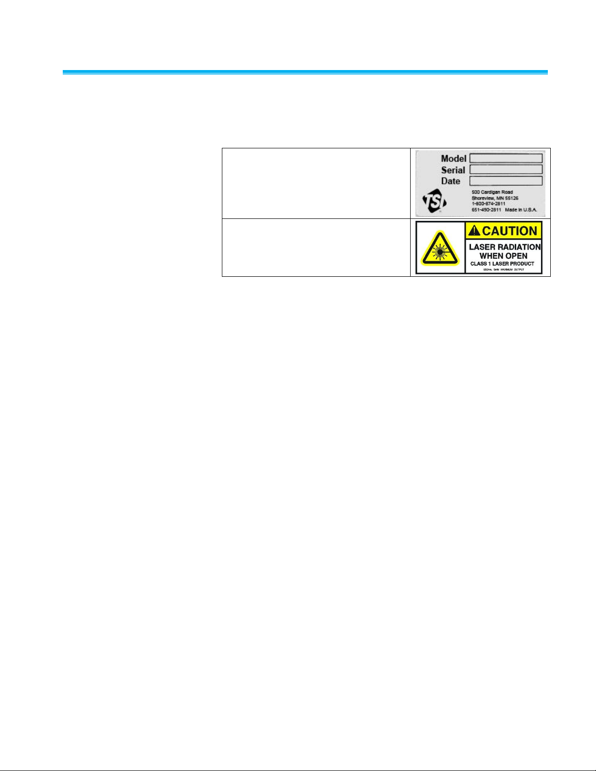
Labels
1. Serial Number Label (back panel)
2. Laser Radiation Label (located
internally on the optics housing)
Advisory labels and identification labels are attached to the outside of the
Laser Photometer housing and to the optics on the inside of the instrument.
Labels for the Model 8587A Laser Photometer are described below:
Safety ix

(This page intentionally left blank)
x Model 8587A Laser Photometer

Contents
Manual History ........................................................................................... iv
Warranty ...................................................................................................... v
Safety ......................................................................................................... vii
Laser Safety ......................................................................................... vii
Description of Safety Labels ................................................................ viii
Caution .............................................................................................. viii
Warning ............................................................................................. viii
Caution or Warning Symbols ............................................................ viii
Labels .................................................................................................... ix
Contents ..................................................................................................... xi
Figures ................................................................................................. xiii
Tables ................................................................................................. xiv
About This Manual ................................................................................... xv
Organization ......................................................................................... xv
Submitting Comments .......................................................................... xv
CHAPTER 1 Introduction ........................................................................ 1-1
Product Description ............................................................................. 1-1
How it Works ....................................................................................... 1-2
CHAPTER 2 Unpacking and Setting Up the Laser Photometer .......... 2-1
Unpacking ........................................................................................... 2-1
Packing List ..................................................................................... 2-1
AC Power Connection ......................................................................... 2-1
Vacuum Pump and Connection .......................................................... 2-2
Flow Check ...................................................................................... 2-2
Connecting the Sample Lines ............................................................. 2-3
CHAPTER 3 Technical Description ........................................................ 3-1
Cabinet ................................................................................................ 3-1
Front Panel .......................................................................................... 3-1
Keypad and LCD Display ................................................................. 3-1
Status Lights .................................................................................... 3-2
Back Panel .......................................................................................... 3-3
Upstream and Downstream Sample Ports ...................................... 3-4
Vacuum Port .................................................................................... 3-4
Analog Output BNC Connector ....................................................... 3-4
Serial Communications Port ............................................................ 3-5
USB Communication Port ................................................................ 3-5
Data Acquisition and Instrument Control ............................................ 3-6
Serial Communications Protocol ..................................................... 3-6
USB Communications ...................................................................... 3-6
USB Terminal Emulator Program .................................................... 3-6
Command Strings for Instrument Control and Data Acquisition ...... 3-7
Hex Data Retrieval ........................................................................... 3-8
Decimal Data Retrieval .................................................................... 3-8
DATA Averaging .............................................................................. 3-9
xi

Programming Note .......................................................................... 3-9
Flow System ....................................................................................... 3-9
Vacuum Pump .................................................................................... 3-9
Sensor (Scattering Chamber) ........................................................... 3-11
Laser Photometer Electronics........................................................... 3-13
Internal Instrument Components ...................................................... 3-14
Sensor Assembly ........................................................................... 3-15
Filters ............................................................................................. 3-15
Solenoid Valves ............................................................................. 3-15
Pressure Transducer ..................................................................... 3-16
Electronics Boards ......................................................................... 3-16
CHAPTER 4 Instrument Operation ........................................................ 4-1
Turning on the Laser Photometer ....................................................... 4-1
Keypad Pushbuttons ........................................................................... 4-1
Vacuum Pump Requirements ............................................................. 4-2
Connecting Sample Lines ................................................................... 4-3
Flow Setup .......................................................................................... 4-3
Fit Test Chamber Requirements ........................................................ 4-3
Performing Fit Tests ........................................................................... 4-4
Test Control ..................................................................................... 4-4
Performing a Fit Test Manually ....................................................... 4-4
Fit Test Under Computer Control .................................................... 4-5
Filter Testing Aerosol .......................................................................... 4-6
Performing a Filter Test ...................................................................... 4-7
CHAPTER 5 Maintenance and Service .................................................. 5-1
Filter Replacement .............................................................................. 5-1
Filter Replacement Instructions ....................................................... 5-2
Sensor Contamination ........................................................................ 5-2
Changing Sample Flow ....................................................................... 5-3
Technical Contacts ............................................................................. 5-4
Returning the Laser Photometer for Service ...................................... 5-5
APPENDIX A Specifications .................................................................. A-1
APPENDIX B Laser Photometer CD ..................................................... B-1
Accessing the Laser Photometer CD ................................................ B-1
USB Terminal Emulator Program ...................................................... B-2
Installing the USB Terminal Emulator ............................................ B-2
Connecting USB for the First Time .................................................... B-7
Installation Issues That May Arise ................................................ B-10
Stopping the Device ..................................................................... B-10
Uninstalling the Device ................................................................. B-10
Driver File Locations ..................................................................... B-10
Starting the Program .................................................................... B-11
Listing Available Devices .............................................................. B-11
Connecting to a Device ................................................................ B-11
Sending Commands ..................................................................... B-12
Disconnecting ............................................................................... B-12
Saving Input and Output ............................................................... B-12
Setting Timeouts ........................................................................... B-13
Setting the Buffer Size .................................................................. B-13
xii Model 8587 Laser Photometer

APPENDIX C Technical Information for Program Development
Using USB Communications .......................................................... C-1
Locating the Header File .................................................................... C-1
Locating the Library ........................................................................... C-2
Locating the Dynamic Link Library File .............................................. C-2
Using the Library ................................................................................ C-2
Error Values and Interpretation .......................................................... C-2
Troubleshooting Win32 Errors ........................................................ C-3
USB Command Status Errors ......................................................... C-4
Device Operation ............................................................................... C-4
Windows Registry Settings ................................................................ C-5
Connecting to the Attached Device.................................................... C-5
ListDevices...................................................................................... C-5
DeviceOpen .................................................................................... C-6
Communicating with the Attached Device ......................................... C-7
TsiUsbTerminalTransmit ................................................................. C-7
TsiUsbTerminalReceive .................................................................. C-8
Retrieving Error Strings .................................................................... C-10
TsiUsbGetStatusString ................................................................. C-10
TsiUsbGetWin32String ................................................................. C-11
Closing the Connection .................................................................... C-11
DeviceClose .................................................................................. C-11
Index
Reader’s Comments Sheet
Figures
1-1 Model 8587A Laser Photometer ....................................................... 1-2
3-1 Back Panel of the Model 8587A Laser Photometer .......................... 3-3
3-2 Serial Communications Port .............................................................. 3-5
3-3 Flow Schematic Model 8587A Laser Photometer ........................... 3-10
3-4 Sheath Air Flow System .................................................................. 3-12
3-5 General Location of Internal Components of the
Model 8587A Laser Photometer .................................................... 3-14
B-1 Introduction Screen .......................................................................... B-2
B-2 TSI USB Device Driver InstallShield Wizard Screen ....................... B-3
B-3 License Agreement Screen ............................................................. B-4
B-4 Choose Destination Location Screen .............................................. B-4
B-5 Begin Installation Screen ................................................................. B-5
B-6 Setup Status Screen ........................................................................ B-5
B-7 InstallShield Wizard Complete Screen ............................................ B-6
B-8 TSI USB Terminal Shortcut Icon ...................................................... B-6
B-9 Found New Hardware Wizard Screen ............................................. B-7
B-10 Hardware Wizard Installing Software ............................................... B-8
B-11 Unsigned Driver Warning Screen .................................................... B-8
B-12 Please Wait While Wizard Installs Software Screen ....................... B-9
B-13 Completing the Found New Hardware Wizard Screen .................... B-9
B-14 Terminal Program Screen .............................................................. B-11
B-15 Saving Input and Output ................................................................ B-12
Contents xiii

Tables
B-16 Set Device Timeout Screen ........................................................... B-13
B-17 Set Polling Buffer Size Screen ...................................................... B-13
2-1 Model 8587A Laser Photometer Packing List ................................... 2-1
3-1 Pin Function for Serial Communications Port ................................... 3-5
3-2 Laser Photometer ASCII Command Strings ..................................... 3-7
4-1 Example Fit Test Sequence .............................................................. 4-6
5-1 Filter Replacement Schedule ............................................................ 5-1
A-1 Model 8587A Laser Photometer Specifications .............................. A-1
xiv Model 8587 Laser Photometer

Organization
About This Manual
The following is a guide to the organization of this manual:
Chapter 1: Introduction
Describes the instruments and provides a brief overview of operation.
Chapter 2: Unpacking and Setting Up the Laser Photometer
Describes the unpacking of the instrumentation, physical setup of the
Laser Photometer, connection of sampling and vacuum line tubing.
Chapter 3: Technical Description
Provides significant detail on instrument components.
Chapter 4: Instrument Operation
Provides a guide to using the instrument for respirator fit tests and filter
testing.
Chapter 5: Maintenance and Service
Provides a guide to instrument maintenance and service.
Appendix A: Specifications
Provides instrument specifications.
Appendix B: Laser Photometer CD
Provides useful information and describes the software programs for
expanding the functionality of the instrument.
Appendix C: Technical Information for Program Development
Using USB Communications
Describes the software development library found on the Model 8587A
Laser Photometer CD-ROM supplied with the instrument.
Submitting Comments
TSI values your comments and suggestions on this manual. Please use
the comment sheet on the last page of this manual to send us your opinion
on the manual’s usability, to suggest specific improvements, or to report
any technical errors. If the comment sheet has already been used, please
mail your comments on another sheet of paper to:
TSI Incorporated
Particle Instruments
500 Cardigan Road
Shoreview, MN 55126
Fax: (651) 490-3824
E-mail Address: particle@tsi.com
xv

(This page intentionally left blank)
xvi Model 8587A Laser Photometer

C H A P T E R 1
Introduction
This chapter contains an introduction to the Model 8587A Laser
Photometer and provides a brief explanation of how the instrument
operates.
Product Description
The Model 8587A Laser Photometer measures aerosol concentrations for
determining the fit factor of particle protection respirators, and for
determining air filter efficiency.
To perform a fit factor test or filter efficiency test, aerosol is sampled from
two separate sampling ports. The sample ports are found at the back of the
instrument labeled UPSTREAM and DOWNSTREAM. When the Model
8587A is used for fit testing, the UPSTREAM port is used to sample
aerosol from the test chamber. The DOWNSTREAM port is used to sample
aerosol from within the mask.
For filter efficiency testing, the UPSTREAM port samples aerosol before it
passes through the filter, the “challenge aerosol”. The DOWNSTREAM port
is used to sample the aerosol concentration after passing through the filter.
The Model 8587A Laser Photometer sensor has special features which
make it unique from older light scattering devices using white light as their
light source. These features have dramatically improved sensitivity,
simplified operation and reduced maintenance. The special features of the
sensor are listed below:
Solid-state laser diode light source and photodiode detector
45 degree off-axis light collection angle
Sheath-air flow design
Fast purge mode capability
Microprocessor driven
Automatic gain selection (six decades)
Remote operation capability using a computer
Front panel switch for selecting between two sampling ports,
Downsteam and Upstream.
1-1

How it Works
Figure 1-1
Model 8587A Laser Photometer
The Model 8587A Laser Photometer determines aerosol concentration by
measuring the level of scattered light produced by aerosol particles as they
are passed through a collimated laser beam in the aerosol sensor
assembly. Scattered light is collected by a photosensitive detector, and a
voltage signal is produced. This signal, minus a small voltage offset, is
proportional to the aerosol mass concentration.
The Laser Photometer transmits signal voltage readings to the front panel
LCD display in scientific notation. Voltages can be accessed by a computer
too, connected to the RS-232 Serial or USB connectors using a
communications cable. Computer control enables automated respirator fit
and filter testing, in addition to other applications.
1-2 Model 8587A Laser Photometer

Unpacking
C H A P T E R 2
Unpacking and Setting
Up the Laser
Photometer
Use the information in this chapter to unpack the Model 8587A Laser
Photometer and set it up.
The following instruments and accessories comprise the Model 8587A
Laser Photometer.
Packing List
Table 2-1 shows the components shipped with your Model 8587A Laser
Photometer.
Table 2-1
Model 8587A Laser Photometer Packing List
Qty. Description Part No.
1 Operation manual 1980538
1 Power cord 110-120V 1303053
220-224V 1303075
1 Exhaust filter 1602230
1 Purge air filter 1602094
1 Sheath air filter 1602051
1 9-pin serial interface cable 6-foot 962002
1 6-foot USB interface cable 1303740
1 CD with USB terminal program 1031502
AC Power Connection
The Laser Photometer uses an on-board power supply capable of
operating with supplied AC power in the range of 100–240 VAC and
50-60 Hz. A detachable power cord is provided and is connected at the
cabinet back. Plug the power cord into a suitable voltage source.
2-1
Vacuum Pump and Conne c tion
N o t e
Stable airflows are extremely important in obtaining repeatable test
results. TSI strongly suggests the instrument be operated with a vacuum
greater than 55 kPa (8.0 psi). At a vacuum of greater than 55 kPa
(8.0 psi) an internal critical orifice limits and stabilizes the sample airflow
to 2.0 L/min (0.07 cfm). Repeatable test results will ONLY be obtained
with stable sample airflows.
The Laser Photometer requires the use of a high vacuum pump, sufficient
to draw >2 L/min (.07 cfm) at 55 kPa (8 psi) vacuum pressure and provide
a free flow of between 12 and 30 L/min (0.43–1.1 cfm).
The vacuum pump is connected to the back of the instrument at the
6.4 mm (¼ in.) tube connection labeled VACUUM. Use a plastic tube to
connect from the vacuum inlet port on the pump to the instrument. Use
tubing which will not collapse under the vacuum load >55 kPa (8 psi).
Flow Check
The Model 8587A verifies the airflow provided by an external vacuum
pump by monitoring the vacuum during upstream and downstream sample
modes. This ensures that a critical pressure is maintained during sampling,
and in turn, a critical airflow for sampling. An operating pressure and
airflow of >55 kPa at 2 L/min (8.0 psi at 0.07 cfm) are recommended. The
minimum vacuum and airflow required is 30 kPa at 1.79 L/min. (4.4 psi at
0.063 cfm) but at the minimum vacuum and airflow, the test data will not be
repeatable.
When the vacuum is greater than 30 kPa (4.4 psi), the FLOW STATUS
light on the front panel turns ON. An illuminated FLOW STATUS light
indicates proper operation. If the FLOW STATUS is BLINKING, the
vacuum is not sufficient and less than 30 kPa (4.4 psi). If the FLOW
STATUS is not ON or BLINKING, first check to make sure the unit is
operating in the UPSTREAM or DOWNSTREAM modes. The FLOW
STATUS is not functional in the PURGE mode. Second, check that there
are no leaks in the vacuum line. Third, if more than one Laser Photometer
shares the same vacuum source, make sure all instruments are connected
and none are in PURGE mode. If one instrument is in the PURGE mode, a
minimum vacuum of 30 kPa (4.4 psi) will not be maintained to the other
instruments.
To independently verify the vacuum, place the Laser Photometer in the
UPSTREAM mode and connect a vacuum gauge to a tee placed in the
vacuum line. If a differential gauge is used, connect to the low pressure
port of the gauge to the vacuum line. TSI strongly recommends a vacuum
of greater than 55 kPa (8 psi). The minimum vacuum must be greater than
30 kPa (4.4 psi).
2-2 Model 8587A Laser Photometer

Connecting the Sample L i n e s
Upstream and Downstream sample lines must be connected at the back of
each Laser Photometer. Tube stubs for tubing connections are labeled
accordingly; UPSTREAM and DOWNSTREAM. Clear ID 4.8 mm (316 in.)
vinyl tubing is recommended for the sample lines. The tubing must be
pushed completely over each tube stub. A touch of silicone grease applied
to the outside of the tube stub will simplify the connection.
Unpacking and Setting Up the Laser Photometer 2-3

(This page intentionally left blank)
2-4 Model 8587A Laser Photometer

Cabinet
C H A P T E R 3
Technical Description
This chapter identifies the basic features of your Model 8587A Laser
Photometer and provides general technical information. Detailed
instrument specifications are provided in Appendix A.
Cabinet dimensions (WDH): 17.8 cm 33.0 cm 25.4 cm
(7 in. 13 in. 10 in.)
Cabinet weight: 5.5 kg (12 lb.)
Front Panel
Front panel features include a 2-line liquid crystal display (LCD), a 3-button
membrane keypad and instrument status lights. The display presents the
photometer signal voltage and indicates the current operation mode, i.e.,
UPSTREAM, PURGE, DOWNSTREAM.
The keypad control buttons are found under the display and are used to
select the sampling mode indicated on the button face, UPSTREAM,
DOWNSTREAM, and PURGE. When sampling upstream or downstream,
the instrument draws sample from the respective sample port at the back
of the Laser Photometer (see the following section). When the photometer
is in the PURGE mode, particle free air is drawn at a high airflow rate into
the photometer’s laser optics chamber and through the purge air filter
shown in the schematic of Figure 3-3.
Keypad and LCD Display
The keypad enables manual switching for sampling from the different
sample ports (UPSTREAM and DOWNSTREAM) and to place the
instrument in a PURGE mode. The keypad buttons are labeled as to
function, UPSTREAM, UPSTREAM, and PURGE.
Note: When switching between UPSTREAM and DOWNSTREAM it is
necessary to pass through the PURGE mode by pressing the
PURGE keypad button.
3-1

Status Lights
OFF
During the PURGE mode, the FLOW STATUS is not
functional and will be off.
If the FLOW STATUS light is OFF during the UPSTREAM
or DOWNSTREAM modes, the instrument is
malfunctioning.
ON
An illuminated FLOW STATUS light indicates proper
operation.
The FLOW STATUS light is illuminated during the
UPSTREAM and DOWNSTREAM sampling modes if
more than 30 kPa (4.4 psi) of vacuum is being supplied to
the respective sample port. 30 kPa (4.4 psi) is the
minimum vacuum needed to obtain the sample airflow for
proper measurements.
BLINKING
A blinking FLOW STATUS light indicates the UPSTREAM
or DOWNSTREAM vacuum is less than what is required
to obtain proper measurements. The FLOW STATUS
light will blink if the UPSTREAM or DOWNSTREAM
vacuum is less than 30 kPa (4.4 psi). If the FLOW
STATUS light is blinking, check for leaks in the vacuum
system or a faulty vacuum pump.
The POWER light indicates the instrument is ON or OFF. An illuminated
POWER light indicates the power is ON.
The FLOW STATUS light has three indications.
3-2 Model 8587A Laser Photometer
(continued on next page)
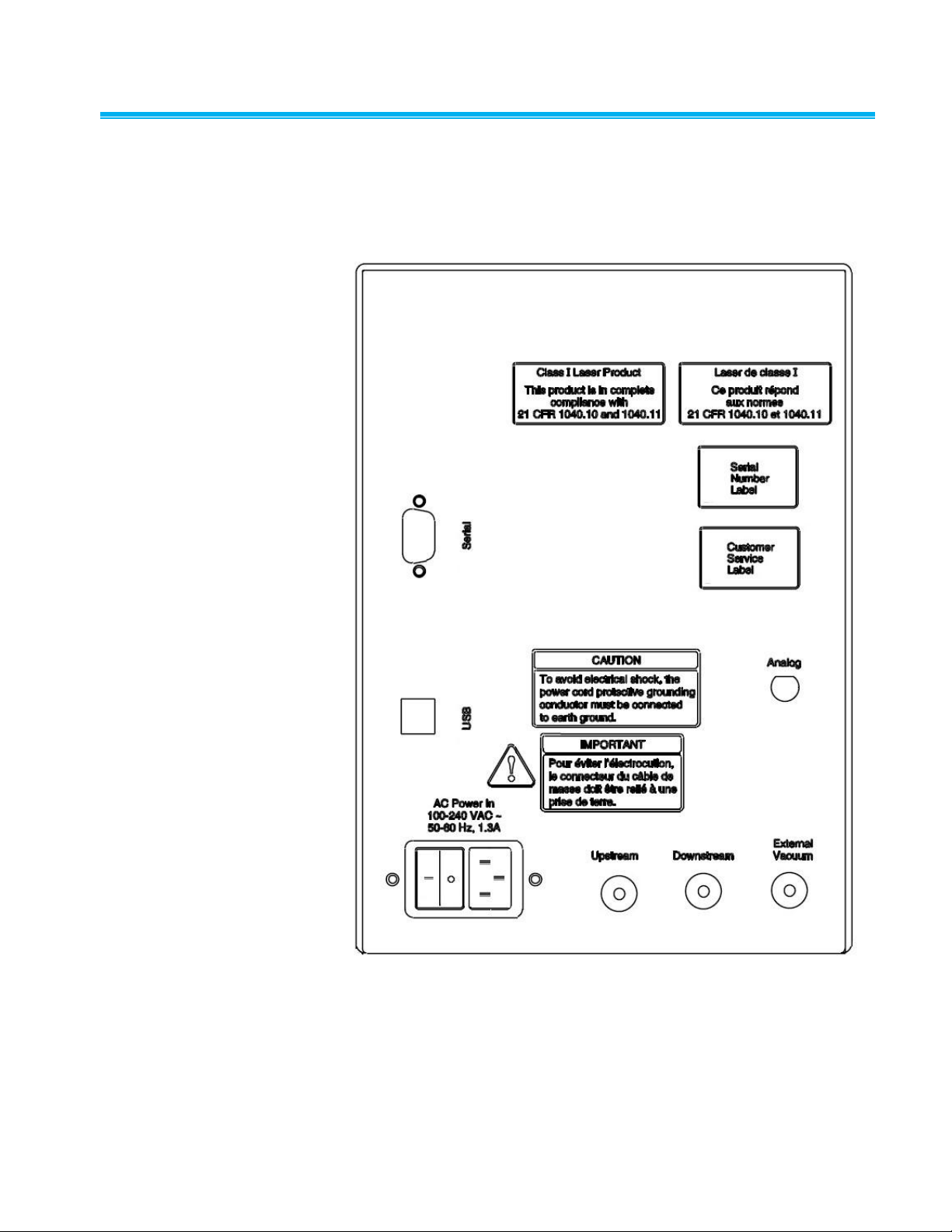
Back Panel
1 Upstream and downstream sample ports
4. 9-PIN D-type female serial connector
2. Port for external vacuum pump connection
5. USB type B connector
3. Power connection
6. Analog voltage BNC connector
The photometer back panel contains the DOWNSTEAM and UPSTREAM
sample and VACUUM ports, the AC power connection/main power switch,
the RS-232 serial port connection, the USB connection, the cabinet cooling
fan, and the analog output BNC connector. The back panel is shown
below:
Figure 3-1
Back Panel of the Model 8587A Laser Photometer
Technical Description 3-3
Upstream and Downstream Sample Ports
N o t e
Stable airflows are extremely important in obtaining repeatable test
results. TSI strongly suggests the instrument be operated with a vacuum
greater than 55 kPa (8.0 psi). At a vacuum of greater than 55 kPa
(8.0 psi), an internal critical orifice limits and stabilizes the sample airflow
to 2.0 L/min (0.07 cfm). Repeatable test results will ONLY be obtained
with stable sample airflows.
Internally the DOWNSTREAM and UPSTREAM sample ports are
connected via plastic tubing to a three-way solenoid valve that switches to
control which port is used.
Tubing is connected from the UPSTREAM sample port to a chamber or the
challenge aerosol side of a filter holder when performing quantitative
respirator fit testing or filter testing.
Tubing is connected from the DOWNSTREAM sample port to a mask or
downstream of the filter when performing fit testing or filter testing,
respectively.
Switching between sample ports is achieved manually by pressing the
appropriate front panel keypad button, or through the RS-232 or USB
interface connectors using computer control codes. It is necessary to select
PURGE as an intermediate step when switching between sampling modes.
Vacuum Port
A vacuum source (vacuum pump) is required to draw the sample airflow
into the photometer scattering chamber. The vacuum pump is connected to
the port labeled VACUUM on the back panel using flexible tubing pushed
over the tube stub. Tubing must be sufficiently rigid so it does not collapse
under the vacuum load.
The instrument is designed for a vacuum of >55 kPa (8 psi) which results in
a very stable sample airflow of 2 L/min (0.071 cfm). TSI strongly
recommends operation with a vacuum greater than 55 kPa (8.0 psi) in
order to obtain repeatable test results. The instrument will function with a
minimum vacuum and airflow of 30 kPa @ 1.79 L/min (4.4 psi @ 0.063
cfm) but the test data may not be repeatable.
Analog Output BNC Connector
The BNC electrical connector on the back panel can be used to monitor the
analog voltage from the Laser Photometer sensor. The output is 0–10 volts
at the minimum detector gain setting. The output has a limited usefulness
at lower signal voltages. Resolution is limited to .01 volts.
3-4 Model 8587A Laser Photometer
 Loading...