


Indoor Air Quality
Q-T
Operation and Service Manual
Model 8550/8551
RAK
TM
IAQ Monitor
1980197, Revision K
October 2002


Model 8550/8551
™
Q-TRAK
IAQ Monitor
Operation and Service
Manual
October 2002
P/N 1980197, Rev. K
SHIP/MAIL TO:
TSI Incorporated
500 Cardigan Road
Shoreview, MN 55126-3996
USA
U.S.
Sales & Customer Service:
(800) 874-2811/(651) 490-2811
Fax:
(651) 490-3824
Sales & Customer Service:
E-mail address:
answers
http://www.tsi.com
INTERNATIONAL
(001 651) 490-2811
(001 651) 490-3824
@tsi.com
Web site:
Fax:

Copyright ©
TSI Incorporated / October 1997–2002 / All rights reserved.
Address
TSI Incorporated / 500 Cardigan Road / Shoreview, MN 55126 / USA
Fax No.
(651) 490-3824
Limitation of Warranty and Liability
Seller warrants the goods sold hereunder, under normal use and service as described in the
operator's manual, shall be free from defects in workmanship and material for twenty-four (24)
months, or the length of time specified in the operator's manual, from the date of shipment to the
customer. This warranty period is inclusive of any statutory warranty. T his limited warranty is
subject to the following exclusions:
a. Hot-wire or hot-film sensors used with research anemometers, and certain other
components when indicated in specifications, are warranted for 90 days from the date of
shipment.
b. Parts repaired or replaced as a result of repair services are warranted to be free from
defects in workmanship and material, under normal use, for 90 days from the date of
shipment.
c. Seller does not provide any warranty on finished goods manufactured by others or on any
fuses, batteries or other consumable materials. Only the original manufacturer's warranty
applies.
d. Unless specifically authorized in a separate writing by Seller, Seller m a kes no warranty
with respect to, and shall have no liability in connection with, goods which are
incorporated into other products or equipment, or which are modified by any person other
than Seller.
The foregoing is IN LIEU OF all other warranties and is subject to the LIMITATIONS stated
herein. NO OTHER EXPRESS OR IMPLIED WARRANTY OF FITNESS FOR
PARTICULAR PURPOSE OR MERCHANTABILITY IS MADE.
TO THE EXTENT PERMITTED BY LAW, THE EXCLUSIVE REMEDY OF THE USER OR
BUYER, AND THE LIMIT OF SELLER'S LIABILITY FOR ANY AND ALL LOSSES,
INJURIES, OR DAMAGES CONCERNING THE GOODS (INCLUDING CLAIMS BASED
ON CONTRACT, NEGLIGENCE, TORT, STRICT LIABILITY OR OTHERWISE) SHALL
BE THE RETURN OF GOODS TO SELLER AND THE REFUND OF THE PURCHASE
PRICE, OR, AT THE OPTION OF SELLER, THE REPAIR OR REPLACEMENT OF THE
GOODS. IN NO EVENT SHALL SELLER BE LIABLE FOR ANY SPECIAL,
CONSEQUENTIAL OR INCIDENTAL DAMAGES. SELLER SHALL NOT BE
RESPONSIBLE FOR INSTALLATION, DISMANTLING OR REINSTALLATION COSTS
OR CHARGES. No Action, regardless of form, may be brought against Seller more than 12
months after a cause of action has accrued. The goods returned under warranty to Seller's
factory shall be at Buyer's risk of loss, and will be returned, if at all, at Seller's risk of loss.
Buyer and all users are deemed to have accepted this LIMITATION OF WARRANTY AND
LIABILITY, which contains the complete and exclusive limited warranty of Seller. This
LIMITATION OF WARRANTY AND LIABILITY may not be amended, modified or its terms
waived, except by writing signed by an Officer of Seller.
Service Policy
Knowing that inoperative or defective instruments are as detrimental to TSI as they are to our
customers, our service policy is designed to give prompt attention to any pr oblems. If any
malfunction is discovered, please contact your nearest sales office or representative, or call TSI's
Customer Service department at (800) 874-2811 (USA) or (001 651) 490-2811 (International).

CONTENTS
1. UNPACKING AND PARTS IDENTIFICATION ............................1
Unpacking the Q-T
RAK ..................................................................1
Parts Identification for the Q-TRAK ................................................2
2. SETTING-UP................................................................................. 3
Supplying Power to the Q-T
RAK .................................................... 3
Installing the Batteries.............................................................3
Using the AC Adapter............................................................. 3
Instrument Setup........................................................................... 3
Setting-up
TRAKPRO Data Analysis Software.......................... 3
Connecting the Q-TRAK to a Computer................................... 3
Set-Up the Communications Port........................................... 4
Setting the Real-Time Clock...................................................5
Programming the Date/Time Using TrakPro ..........................5
Manually Setting the Real-Time Clock ...................................6
Using the Probe Stand............................................................ 6
Connecting the Optional Model 8925 Portable Printer........... 6
3. OPERATION................................................................................. 7
Overview........................................................................................ 7
Keypad Functions.......................................................................... 7
ON/OFF Key..................................................................................7
Key......................................................................................... 8
CO
2
TEMP Key .....................................................................................8
HUMIDITY Key.............................................................................. 9
CO Key (Model 8551 Only)........................................................... 9
SAMPLE Key.................................................................................9
TIME CONSTANT Key.................................................................. 9
Programming the Available Time Constants...............................10
STATISTICS Key.........................................................................10
PRINT Key................................................................................... 11
SAMPLING MODE Key............................................................... 11
Survey Mode:........................................................................11
LOG Modes:.......................................................................... 12
CLEAR MEMORY Key................................................................12
LOGGING INTERVAL Key..........................................................12
Programming the Logging Intervals Using TRAKPRO ...............13
! and " Keys............................................................................. 14
Display/Keypad Lockout Switch.................................................. 14
Programming Advanced Modes: LOG 2 and LOG 3 ..................14
Sample Protocol for LOG 2 and LOG 3 Modes ..........................18
i

Things You Should Know About Taking Pre-Programmed
Samples ...................................................................................19
Memory Considerations...............................................................20
4. CALIBRATION AND MAINTENANCE.......................................21
Calibrating the CO
Concentration Measurement.......................21
2
Calibrating the Temperature or Relative Humidity
Measurement ...........................................................................23
Calibrating the CO Concentration Measurement
(Model 8551 only).....................................................................24
Replacing the CO Sensor............................................................26
Storage Precautions....................................................................27
5. TROUBLESHOOTING................................................................29
APPENDIX A: SPECIFICATIONS.....................................................31
APPENDIX B: INTERNAL DIP SWITCH SETTINGS.......................35
ii

Chapter 1
Unpacking and Parts Identification
Carefully unpack the Q-T
Use the tables and illustrations below to make certain that there are no
missing components. Contact TSI immediately if anything is missing or
damaged.
Packing List for the Model 8550/8551 Q-T
Quantity Item Description Part/Model
1 Q-TRAK IAQ Monitor 8550/8551
1 Carrying Case 800680
4 AA Alkaline Batteries 1206013
1 AC Adapter
115 V, NEMA-5
230 V, Eur., CEE 7/16
230 V, Great Britain
240 V, Australian
1 TRAKPRO Data Analysis Software 800700
1 CO2 Calibration Collar 800678
1 CO Calibration Adapter (Model 8551
only)
1 CO Sensor (Model 8551 only) 800695
1 Probe Stand 800679
1 Computer Interface Cable (RS-232) 800560
1 25-Pin to 9-Pin Serial Cable Adapter 1302690
1 Q-TRAK IAQ Monitor Operation and
Service Manual
1 Certificate of Calibration -
RAK IAQ Monitor from the shipping container.
RAK IAQ Monitor
2613033
2613078
800169
2613105
800696
1980197
1
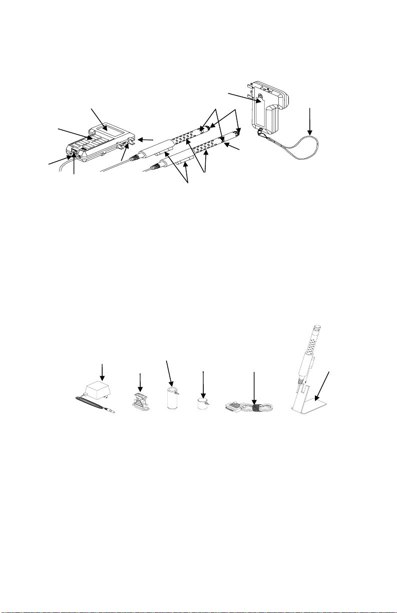
Parts Identification for the Q-T
Figures 1–1 and 1–2 identify the parts of the Q-T
RAK
RAK IAQ Monitor. Please
become familiar with these components before proceeding.
11
1
7
8
12
Model 8550
2
5
13
3
6
4
Figure 1–1: Q-T
10
9
Model 8551
RAK
1. Display 7. Location of Humidity Sensor
2. Keypad 8. Location of Temperature Sensor
3. External Power Socket 9. Location of CO
Sensor
2
4. Data Port RS-232 10. Probe Handle
5. Probe Mounting Clips 11. Battery Access Cover
6. Display/Keypad Lockout 12. Wrist Strap
Switch 13. Location of CO Sensor
(model 8551 only)
1
2
3
6
4
5
Figure 1–2: Q-T
RAK Accessories
1. AC Adapter 4. Computer Interface Cable
2. 25-Pin to 9-Pin Adapter 5. Probe Stand
Calibration Collar 6. CO Calibration adapter
3. CO
2
(Model 8551 Only)
Chapter 1
2

Chapter 2
Setting-Up
Supplying Power to the Q-T
The Q-T
RAK IAQ Monitor must be powered in one of two ways: four size
AA batteries or the supplied AC Adapter.
Installing the Batteries
Insert four size AA batteries as indicated by the diagram located on the
inside of the battery compartment. TSI ships the Q-T
batteries. NiCd rechargeable batteries may also be used.
Using the AC Adapter
The AC Adapter allows you to power the Q-T
outlet. When using the AC adapter, the batteries (if installed) will be
bypassed. The AC adapter is not a battery charger and will not charge
NiCd batteries.
The Q-T
RAK has an internal, non-user accessible battery that is used to
keep memory intact when power is turned off. Changing the AA-size
batteries or disconnecting the AC adapter will not cause data to be lost.
This battery is designed to last for years. TSI will install a new battery,
if necessary, when the unit is returned to the factory for service.
Instrument Setup
The Q-T
RAK comes with special software called TRAKPRO, which is
designed to provide you with maximum flexibility and power when using
the Q-T
RAK. The following sections describe how to install the software and
setup the computer.
Setting-up T
RAKPRO software contains a very comprehensive Help Function. This
T
RAKPRO Data Analysis Software
utility provides all the necessary information to guide you in all aspects
of software operation.
Connecting the Q-T
Each Q-T
RAK comes equipped with an RS-232 cable and a 25-pin to
9-pin serial cable adapter. One end of the cable is a 25-pin D
subminiature connector labeled COMPUTER; the other end is an RJ-45
modular connector that mates with the logging instrument. Serial port
connectors always have pins (male) on the computer side.
RAK
RAK with alkaline
RAK from an AC wall
RAK to a Computer
3
1. Locate an available serial port on your computer: COM1, COM2,
COM3, or COM4.
2. If the port has a 25-pin connector, you do not need the adapter. If
the port has a 9-pin connector, plug the 25-pin end of the adapter
into the RS-232 cable.
Connect the RS-232 cable to the available serial port on your
3.
computer.
Connect the RJ-45 connector to the Q-TRAK.
4.
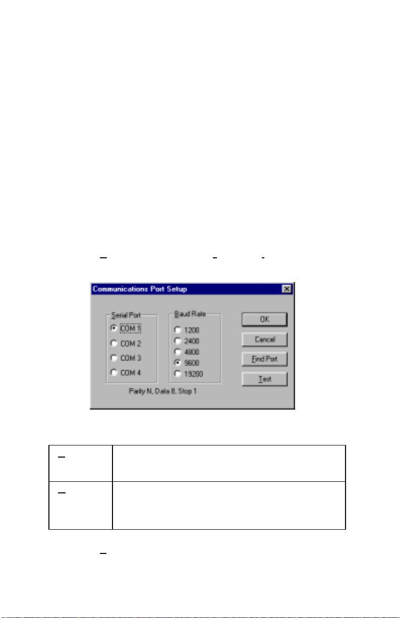
Set-Up the Communications Port
To communicate with the Q-T
the proper COM port. T
specific COM port, or it can automatically find a Q-T
RAK, the software must be configured for
RAKPRO can be manually set to operate on a
RAK that is
attached to any COM port. To set up the COM port, do the following:
1. Turn on the Q-T
2. Select C
following dialog is displayed:
Select the fo llowing:
3.
erial
S
Port
Baud
Rate
RAK and start TRAKPRO.
ommunications from the Instrument Setup menu. The
Select the name of the serial port to which the
logging device is connected: COM1, COM2, COM3,
or COM4.
Select the baud rate for the port. Higher baud rates
are recommended to transfer data at a faster rate.
Select a lower baud rate only if you are having
trouble communicating at a higher rate.
4. Select Test to verify that you have set up the communications port
properly. The system displays an informative message indicating
whether it was able to establish communications.
Chapter 2
4
5. As an alternate, you may select F
ind Port, to have TRAKPRO
search the available COM ports, looking for an attached Q-T
RAK.
6. Select
OK to accept the setup or Cancel to discard the changes.
Note: Some computers do not communicate reliably at baud rates
above 9600.
Setting the Real-Time Clock
The Q-T
RAK has an internal real-time clock that keeps track of the time
of day (the format is HH:MM where HH is the hour in 24-hour format
and the MM is minutes) and the date. It is very important for the
RAK to have the time and date correctly set; otherwise, date and time
Q-T
stamping of recorded data and calibrations will not be correct.
There are two ways to set the time and date. The first is to use the
supplied T
RAKPRO Data Analysis Software.
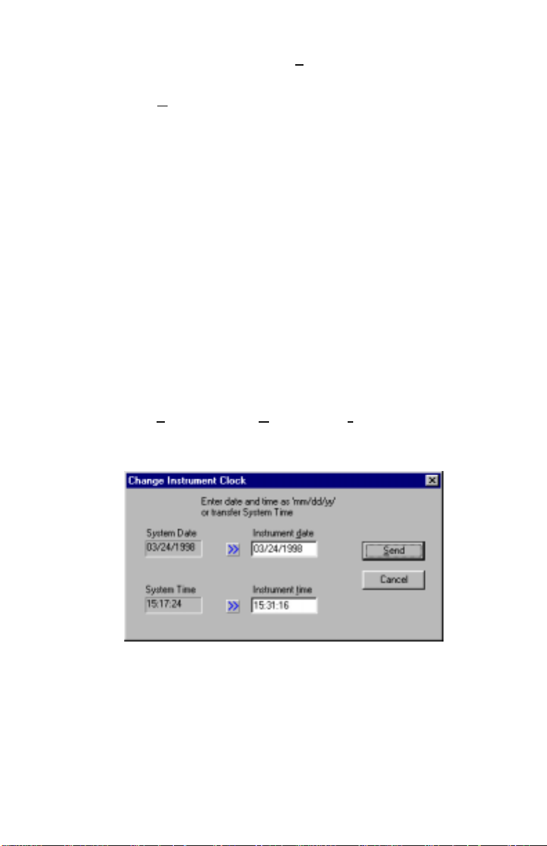
Programming the Date/Time Using TrakPro
To program the Q-T
1. Make sure the Q-T
2.
Select Parameters, then Clock from the Instrument Setup menu.
RAKPRO retrieves the current date and time settings from Q-TRAK
T
RAK date and time:
RAK is connected to the computer and turned on.
and displays them in the following dialog:
3. The system date and time (from the computer) may be transferred
to the Q-T
RAK using the “arrows” keys. Alternately, the date and
time may be manually entered into the dialog box.
4. Select Send to reprogram the Q-T
RAK.
5

Manually Setting the Real-Time Clock
To set the time and date with the keypad, you must press and hold the
SAMPLE key down while the Q-T
its power-up sequence. Release when the Q-T
RAK displays the time of day during
RAK “beeps.” You will
have an opportunity to view and/or change the hours, minutes, year,
month and day of month in sequence. Use the up and down arrow keys
(!") to change a setting. Use the SAMPLE key to store each setting
and advance to the next one.
Using the Probe Stand
For your convenience, the Q-T
RAK is supplied with a probe stand so
that the probe can be located above a table surface while unattended. To
use it, simply detach the probe from the Q-T
RAK mounting clips and
slide it onto the stand.
Connecting the Optional Model 8925 Portable Printer
To connect the Model 8925 printer to the Q-T
RAK, locate the Printer
Interface cable (supplied with optional printer) and connect the 9-pin
end labeled “PRINTER” to the printer and the other end to the data port
on the Q-T
RAK. Always turn the Q-TRAK on BEFORE the printer. If the
printer prints question marks (??????), asterisks (******), or random
characters, reset it by turning it off and then on again. If necessary, refer
to the Model 8925 Portable Printer Operation and Service Manual.
Chapter 2
6

Chapter 3
Operation
Overview
The Model 8550 and Model 8551 Q-T
temperature, and relative humidity. In addition the Model 8551 also
measures CO concentration. All parameters are measured simultaneously in
a single probe. The Q-T
RAK has four modes of operation, Survey, LOG 1,
LOG 2, and LOG 3. When the Q-T
mode which is used to display real-time readings and to determine statistics
such as average, minimum, and maximum readings. LOG 1 mode is used to
record individual data points for later analysis using a factory set protocol.
LOG 2 and LOG 3 modes have user-defined protocols, set up using
RAKPRO software. TRAKPRO software is used for analysis of data taken in
T
any of the three LOG modes, but cannot be used on samples taken in Survey
mode.
Keypad Functions
When pressing the keys on the front panel, the Q-T
the function. If you press a key and the Q-T
does not allow that function during the selected sampling mode. To disable
the beep, refer to Appendix B: “Internal DIP Switch Settings.”
ON/OFF Key
Use the ON/OFF key to turn the Q-T
first turned on it goes through a preprogrammed power-up sequence that
includes an internal self-check. First, all displayable items will appear for a
few seconds. If a problem is detected, the display shows the message
“SERVICE” along with a number to indicate that the Q-T
servicing. Refer to Chapter 5: “Troubleshooting” for information regarding
service numbers. If the “SERVICE” message appears, the Q-T
until any key is pressed.
When the Q-T
RAK completes its internal self-check, it will display the
approximate percentage of battery life remaining. The Q-T
+ –
battery symbol
when the battery voltage becomes very low. After the
battery symbol appears, the Q-T
before displaying the message “LO” (for a few seconds) and then
automatically turning off. This feature is accurate for alkaline batteries only.
The percentage life remaining will not be accurate for NiCd batteries. The
battery symbol appears when battery voltage becomes low, but the Q-T
RAK IAQ monitors measure CO
RAK is first turned on it will be in Survey
RAK will beep to confirm
RAK does not beep, the Q-TRAK
RAK on and off. When the instrument is
RAK requires
RAK pauses
RAK displays the
RAK runs for approximately 60 minutes
,
2
RAK
7

will run considerably less than 60 minutes before displaying the message
g
“LO” and turning off.
CO2 SAMPLE
CALIBRATE ZERO RECORDING
HR:MN:SEC TEST ID LOG 123
CO2 SAMPLE
ELAPSED TIME
PPM
°F°C
%RH
m
CONSTANT
AVERAGE
3
/m
% MEMORY
MIN MAX
SERVICE
Figure 3–1: Q-T
RAK Display With All Elements Shown
After displaying the percentage of battery life remaining, the current time set
on the internal real-time clock is displayed. When the self-check is complete,
the Q-T
RAK will be in Survey mode.
CO
Key
2
Press the CO
key to display CO2 readings. Carbon dioxide concentration
2
readings will be displayed in units of parts per million (ppm). Place the
sensor in the location where you want to take the measurement. The probe
must be fully exposed because the CO
sensor is located between the probe
2
tip and the handle, not at the tip.
Caution
!
TEMP Key
Press the TEMP key to display air temperature readings. The temperature
sensor is located near the tip of the probe. The Q-T
readings in either degrees Celsius (°C) or degrees Fahrenheit (°F) depending
on the DIP switch settings (refer to Appendix B).
Do not hold the probe close to your breathing zone. Humans
exhale CO
and this will influence the readings.
2
RAK displays temperature
Caution
!
Do not use the Q-TRAK to measure the temperature of liquids.
The sensor is not designed for submersion.
8
Chapter 3

HUMIDITY Key
Press the HUMIDITY key to display humidity readings. The humidity sensor
is located near the tip of the probe. The readings will be in u nits of percent
relative humidity (%rh).
Caution
!
CO Key (Model 8551 Only)
Press the CO key to display CO readings. Carbon monoxide concentration
readings are displayed in units of parts per million (ppm). The CO sensor is
located at the tip of the probe.
SAMPLE Key
Press the SAMPLE key to start/stop data sampling. The word “SAMPLE”
appears in the upper-right corner of the display while the Q-T
sample. When sampling is stopped, the Q-T
through statistics for the sample that just ended.
TIME CONSTANT Key
Momentarily press and release the TIME CONSTANT key to view the
current time-constant. To change the time-constant, press and hold the key
down. The available time-constant choices will sequence on the display.
When the desired value is displayed, immediately release the key.
The time-constant is actually an averaging period. The Q-T
always updated every second; however, the reading displayed is the average
reading over the last time-constant period. For example, if the current timeconstant is set to 10 seconds, the display shows readings averaged over the
previous 10 seconds, updated every second. This is also called a 10-second
“moving average.”
As configured at the factory, the available time-constant values are 2, 5, 10,
15, and 20 seconds. The internal list of time-constant values can be altered
using Q-T
of time constants allowed is 2–60 seconds. See the following instructions.
The humidity sensor is sensitive to the effects of water. Do not
expose the sensor to liquid water. This will damage the sensor.
Also, the humidity sensor will not function properly while
exposed to intense light, such as direct sunlight. Shade the
probe to avoid false readings.
RAK is taking a
RAK automatically scrolls
RAK display is
RAK Data Analysis Software supplied with the Q-TRAK. The range
Operation
9

Programming the Available Time Constants
To program the list of time constants using Q-T
RAK Data Analysis Software:
1. Make sure the Q-T
2.
Select Parameters, then Time Constants from the Instrument Setup
menu. T
Q-T
RAKPRO retrieves the current time constant settings from the
RAK and displays them in the following dialog:
RAK is connected to the computer and turned on.
Enter a value for each of the five available time constants. (The range is
3.
limited to 2–60 seconds.)
Select Send.
4.
The Q-T
RAK is reprogrammed to offer the time constants you have
specified.
STATISTICS Key
Use the STATISTICS key to sequentially view the average, minimum, and
maximum readings as well as the elapsed time of the most recently sampled
data. You may view sample statistics while the sample is in-progress;
however, one time-constant must have elapsed first. If one of the LOG
modes is active, a test identification number is displayed also. Press the
STATISTICS key once to display the average reading, again to display the
minimum reading, again to display the maximum reading, and again to
display the elapsed time for that sample (and again for the test ID if in LOG
mode). If you press the STATISTICS key a fifth time (sixth time if in LOG
mode), the Q-T
RAK switches back into the currently selected measuring
mode. You must sequence through all four statistic displays (i.e., press the
STATISTICS key five times, six if in LOG mode) before the Q-T
RAK goes
back into the currently selected measuring mode. All parameters are
10
Chapter 3

measured simultaneously. The display shows only the data for the current
measurement mode. The measurement mode may be changed at any time to
view statistics for the other measurements.
PRINT Key
Use the PRINT key to print information on the optional Model 8925
Portable Printer. The information printed will be different depending on
what the Q-T
RAK is currently doing.
When the Q-T
RAK is displaying real-time readings, pressing the PRINT key
will cause all parameters being measured to be printed along with the time
and date. Each time the PRINT key is pressed, one set of values prints. The
values printed reflect the current time-constant; therefore, they are the same
as would be displayed.
When the Q-T
RAK is displaying any statistic, pressing the PRINT key will
cause the current statistics to print. All statistics are printed as a set
regardless of which one is currently displayed.
When the Q-T
RAK is in one of the LOG modes and is idle (“%MEMORY” is
displayed), pressing the PRINT key will cause the logging setup for the
current LOG mode to print.
If you press and hold the PRINT key during the power-up sequence, and
you have the optional Model 8925 printer connected, a printout showing
certain system information occurs.
SAMPLING MODE Key
The SAMPLING MODE key allows you to select between the four
sampling modes: Survey, LOG 1, LOG 2, and LOG 3. Each time you press
the SAMPLING MODE key, the Q-T
When the Q-T
RAK is in Survey mode, the current measurement is shown on
RAK will sequence to the next mode.
the display. When one of the LOG modes is selected, the LOG mode
number, i.e., “LOG 1,” “LOG 2,” or “LOG 3” is displayed along with the
percentage of free memory available.
Survey Mode:
When the Q-T
Survey mode allows you to make simultaneous measurements of CO
RAK is first turned on, it will always be in Survey mode.
2
concentration, temperature, and relative humidity, and to obtain
statistics for each measurement when a sample is taken. The statistics
include the average, minimum, and maximum values, as well as the
elapsed time for that sample. Individual data points are not recorded
(this can be done in any of the LOG modes). Each new sample taken in
Survey mode clears the previous sample data from memory. Data taken
in Survey mode remains in memory until another sample is made, or
Operation
11

until samples are taken in one of the LOG modes. Turning the Q-T
RAK
off will not erase data. Use the SAMPLE key to start and stop a sample.
LOG Modes:
There are three LOG modes: LOG 1, LOG 2, and LOG 3. When one of
these modes is selected using the SAMPLING MODE key, the LOG
mode number is listed at the top of the display. The LOG modes allow
you to record data points for later retrieval and analysis using the
software provided with the instrument.
Use the SAMPLE key to start and stop recording. The word
“RECORDING” appears at the top of the display when recording is in
progress. Use the CO
, TEMP HUMIDITY, or CO keys to select which
2
measurement is displayed during recording.
The frequency that data is recorded can be set for LOG 1 mode with the
LOGGING INTERVAL key. Use T
RAKPRO software for LOG 2 and
LOG 3 modes.
Data recorded using one of the LOG modes can only be erased by using
the CLEAR MEMORY key. Turning the Q-T
RAK off will not erase
data. Recording another sample with one of the LOG modes, without
clearing memory first, causes new data to be added to the existing data
(using a new test ID).
CLEAR MEMORY Key
Use the CLEAR MEMORY key to erase all data. The CLEAR MEMORY
key will not respond unless the Q-T
RAK is first put into one of the three
LOG modes by using the SAMPLING MODE key.
Note: You should first download your data to your computer through the
RAKPRO software. There is only one block of memory in the
T
RAK. Clearing the memory for one LOG mode clears memory for
Q-T
all LOG modes.
To clear memory, press and hold the CLEAR MEMORY key until the
countdown reaches zero, then release quickly. This prevents accidental
erasure of data. Releasing the key too soon or too late prevents memory
from being cleared … try again.
LOGGING INTERVAL Key
Use the LOGGING INTERVAL key to view or set the frequency/averaging
period for recording data in LOG 1 mode or to view the current interval
setting in LOG 2 and LOG 3 mode. Use T
RAKPRO software to set the
logging interval for LOG 2 and LOG 3 mode. The LOGGING INTERVAL
12
Chapter 3

key will not respond unless the Q-T
RAK is first put into one of the three
logging modes. Press the LOGGING INTERVAL key momentarily to view
the current logging interval. Press and hold the LOGGING INTERVAL key
to sequence through the available choices and release the key when the
desired interval is on the display (LOG 1 mode only).
The logging interval is both a frequency and an averaging period. For
example, when the logging interval is set to 30 minutes, readings will be
recorded at 30-minute intervals. Each reading will be the average value
measured over that 30-minute interval.
As shipped from the factory, the available logging intervals for LOG 1 mode
are 1 second, 1 minute, 5 minutes, 15 minutes, and 30 minutes. Use the
RAKPRO data analysis software to alter these values.
T
Programming the Logging Intervals Using T
RAKPRO
To program the list of logging intervals available for LOG 1 mode:
1. Make sure the Q-T
2.
Select Parameters, then Logging Intervals from the Instrument
Setup menu. T
RAK and displays them in the following dialog:
Q-T
RAK is connected to the computer and turned on.
RAKPRO retrieves the current logging intervals from the
3.
Enter a value for each of the five available logging intervals (the range
is from 1 second to 59 minutes and 59 seconds).
Select Send.
4.
Operation
13

The Q-T
RAK is reprogrammed to offer the logging intervals you have
specified.
! and " Keys
The two arrow keys are used to adjust readings when calibrating the
RAK and for adjusting the time and date for the internal real-time clock.
Q-T
Display/Keypad Lockout Switch
Recording data over extended time periods often requires leaving the
RAK unattended. To reduce the risk of having an unauthorized person
Q-T
either intentionally or inadvertently interrupt the measurements, you can
lock the display and keypad.
This switch is located on the side of the Q-T
RAK between the probe
mounting brackets. It is a small slide switch and is recessed so that a pointed
instrument must be used to move it.
The instrument case is labeled next to the switch with the symbols “I” and
“0.” With the switch in the “I” or on (up) position, all keypad and display
functions will work normally. There are two ways to use the lockout switch.
You can lock the keypad (move the switch to the “0” position) after
recording starts, or you can put the switch into the lockout position prior to
when recording starts. If you select the second method, you will be able to
operate all functions normally until the SAMPLE key is pressed in one of
the LOG modes. At that time the keypad will automatically lock. When the
display and keypad are locked, the display shows the words “RECORDING
LOG X "” where “X” is the current LOG mode number.
Programming Advanced Modes: LOG 2 and LOG 3
Use LOG 2 or LOG 3 modes for unattended recording and setting user
protocols. With LOG 2 and LOG 3 modes you can set the start date, start
time, test length, logging interval, number of tests, and the time delay
between tests. All or selected parameters can be set.
To program a protocol for LOG 2 or LOG 3 mode:
1. Make sure the Q-T
RAK is connected to the computer and turned on.
2. Select Logging Setup from the Instrument Setup menu. T
retrieves the current settings for LOG 2 and LOG 3 modes from the
RAK and displays them in the following dialog:
Q-T
14
RAKPRO
Chapter 3

The following table summarizes the information displayed in the
Advanced Logging Modes dialog box:
Serial Number
Number of tests
logged
Available
Memory (%)
Displays the serial number of the logging
instrument.
Displays the number of tests currently logged
and stored in the logging instrument.
Displays the percent of available memory in
the logging instrument.
Operation
15

LOG 2 and LOG 3 Mode Protocols
Channels
Start Date
Start Time
Log interval
Test length
Number of tests
Time between
tests
Percent
memory
required.
Displays the channels selected for sampling in
LOG 2 and LOG 3 modes.
Displays the start date for LOG 2 and LOG 3
modes.
Displays the start time for LOG 2 and LOG 3
modes.
Displays the log interval for LOG 2 and LOG
3 modes.
Displays the test length for LOG 2 and LOG 3
modes.
Displays the number of tests for LOG 2 and
LOG 3 modes.
Displays the time between tests for LOG 2
and LOG 3 modes.
Displays the percent of logger memory
required to perform a LOG 2 or a LOG 3
mode sample. To store the results of a LOG 2
or LOG 3 mode sample, the Available
Memory must be equal to or greater than the
Percent memory required.
16
Chapter 3

3.
Enter the following for LOG 2 and LOG 3 modes:
Channels
Start Date
Start Time
Select the channels for which you want to log
data. In the case of the Q-T
channels to select: CO
RAK, there are four
, Temp, rh, and CO.
2
Enter the date and time to begin the sample:
• If you enter a blank for a start date, the
sample begins whenever the specified start
time occurs.
• If you enter a blank for the start time, both
start date and start time are ignored, and
the sample begins when the operator
manually starts the sample.
Log interval
Test length
Enter the log interval to use for the test.
Enter the length for the sample:
• If you enter a value, the instrument
automatically turns off when the last test is
complete.
• If you enter a blank, the operator must
manually stop the sample.
Number of tests
Time between
tests
Enter the number of tests to perform.
If you have specified more than one Number
of tests, enter the time between tests. If you
enter 0 or blank, the next test is started
immediately after the last test is complete.
While you are entering values for LOG 2 and LOG 3 modes, the
Percent Memory Required is dynamically updated to show the amount
of logger memory required to take the programmed sample. If the
protocol you have defined requires more than 100% of memory, you
can decrease the amount of memory required by manipulating the
following protocol parameters:
• Increase the logging interval.
• Decrease the length for the test.
• Decrease the number of tests.
• Decrease the number of channels.
The settings for each LOG mode must not require more than 100% of
the logger memory. Note also that if the Percent memory required is
greater than the Available memory, the logging instrument
automatically stops the test when memory is full.
Operation
17

4.
Wh en you have finished defining the parameters for LOG 2 and LOG 3
modes, select S
end.
5. You can now disconnect the Q-T
RAK and cable from the computer.
Sample Protocol for LOG 2 and LOG 3 Modes
The following steps describe how to program a sample protocol for LOG 2
or LOG 3 mode.
The sample protocol for LOG 2 is set to take unattended readings for one
day, 3/23/98. The logging sample begins at 8:00 a.m. and continues for
8 hours.
The sample protocol for LOG 3 is set up to take unattended readings for two
days, beginning on 3/24/98. The logging sample begins at 8:00 a.m. and
continues for 8 hours. The instrument is off for 16 hours, and then repeats
the 8 hours test on the following day.
The following graphic gives the appearance of the dialog box displayed in
RAKPRO, with these particular logging parameters.
T
To program this logging example, do the following:
1. Make sure the Q-T
RAK is connected to the computer and turned on.
18
Chapter 3

2. Select L
ogging Setup from the Instrument Setup menu. TRAKPRO
retrieves the current settings for LOG 2 and LOG 3 modes from the
RAK and displays them in the previous dialog.
Q-T
3. Enter the following for LOG 2 and LOG 3:
Setting
Channels
Start Date
Start Time
Log interval
Test length
Number of tests
Time between
LOG 2 LOG 3
CO
, Temp, rh, CO CO2, Temp, rh, CO
2
03/23/1998 03/24/1998
08:00 08:00
01:00 05:00
00:08:00 00:08:00
1 2
00:00:00 00:16:00
tests
4. Select Send. The logging instrument is programmed for the mode 2 and
mode 3 protocols.
5. Note that the LOG 2 test requires 3% of the available memory and LOG
3 requires 1% of the memory. A total of 98% of the memory is available
for use.
6. You can now disconnect your Q-T
RAK from the computer. Refer to
other sections of this Operation and Service Manual for details on
making measurements using LOG 2 and LOG 3 modes.
After programming the Q-T
take the Q-T
RAK to the desired location and turn it on. Put it into LOG 2 or
RAK with the TRAKPRO Data Analysis Software,
LOG 3 mode (whichever you programmed) using the SAMPLING MODE
key. Press the SAMPLE key to initiate the program.
If you have set a start time and/or date, the display toggles between the next
“TEST ID” and the “ELAPSED TIME 0” message. If the test start time is
greater than one minute away, the Q-T
the test start time. This indicates that the Q-T
RAK shuts off until one minute before
RAK is waiting until the
programmed start time and dates occur. You may want to lockout the display
and keypad at this time to prevent tampering.
Things You Should Know About Taking Pre-Programmed Samples
If you press the SAMPLE key during programmed recording, the
program terminates (unless the keypad is locked).
If the programmed start time and date has already passed, pressing the
SAMPLE key has no effect. The program never executes.
Operation
19

Setting the start time but no start date causes the Q-T
specified time regardless of the date.
RAK to start at the
If no start time is set, the Q-T
RAK waits for you to press the SAMPLE key
and starts sampling immediately.
If no test length is set, the Q-T
RAK samples continuously until the
SAMPLE key is pressed to stop sampling or until the memory is full.
When a pre-programmed test ends, the Q-T
RAK automatically shuts off.
When it is turned on again, it will be in Survey mode.
Memory Considerations
The Q-T
be concerned with running out. The Q-T
RAK has a great deal of memory and you will not normally have to
RAK has 128,000 bytes of internal
memory. This should be considered when selecting a logging interval.
Shorter logging intervals use memory more quickly than longer intervals.
A recorded data set consumes 6 bytes for Model 8550 and 8 bytes for
Model 8551 (2 each for CO
, CO, temperature and humidity.) In addition,
2
each test (labeled with a TEST ID number) needs 100 bytes for storing
statistics and setup information. (The formulas below ignore this 100 bytes
to keep the calculations simpler.) Based on this information, the Q-T
RAK is
capable of storing approximately 21,000 data sets for Model 8550 and
15,750 for Model 8551:
Note: LOG 2 and LOG 3 modes can be programmed to record any of the
measurements separately, i.e., only CO
, or CO2 and temperature
2
but not humidity, etc. If only one measurement is recorded, up to
63,000 data points could be stored. The discussion below assumes
four measurements are recorded.
ointsMax Data P =≈
000,128
8
000,16
Therefore 1% of memory is about 160 data sets. The maximum possible
duration of a data logging session is determined by the logging interval and
the available memory. The equation below can be used to determine any
memory, recording time or logging interval restraints.
Memory%
[]
≈
[][ ]
×
Time Elapsed
Interval Logging160
(Note: Elapsed Time and Logging Interval are in units of minutes.)
20
Chapter 3

Chapter 4
Calibration and Maintenance
The Q-T
The Q-T
Even so, we recommend that you return your Q-T
annually. For a reasonable fee, we will quickly clean and recalibrate the unit,
update software and firmware, and return it to you in “as new” working
condition along with a Certificate of Calibration and NIST Traceability. The
factory calibration is more precise than can be accomplished with the
procedures below. This “annual checkup” helps ensure that the Q-T
always in good operating condition.
Calibrating the CO
TSI recommends calibrating the Q-T
ensure accurate readings. The CO
changes in atmospheric pressure. Normal day-to-day variations due to local
weather conditions have little effect. However, changes in altitude can cause
more significant errors. For best accuracy, calibrate the Q-T
measurement for your local conditions or if conditions change.
To calibrate the CO
instructions can also be found on the calibration collar itself. You will need a
cylinder of pure air or nitrogen for the zero calibration and a cylinder of gas
with a known concentration of CO
local TSI distributor for available CO
Note: If using air for calibration, it must be specified to have less than
If necessary, you can select between the factory CO
calibration. Please refer to Appendix B: “Internal DIP Switch Settings.”
The calibration procedure can be aborted at any time by pressing the CO
TEMP, or HUMIDITY key.
If an error occurs during the CO
displays the message “ERR.” Press the CO
abort the calibration. Switching the zero gas with the span gas is an example
of a condition that causes the “ERR” message to come on.
RAK requires very little maintenance to keep it performing well.
RAK may be calibrated in the field using the instructions below.
RAK to TSI for calibration
RAK is
Concentration Measurement
2
10 ppm CO
RAK CO
concentration measurement is affected by
2
sensor, please follow the procedure below. Brief
2
for the span calibration. Contact your
2
2
. Ambient room air cannot be used.
2
calibration procedure, the Q-TRAK
2
measurement monthly to help
2
RAK CO
calibration kits.
calibration and a user
2
, TEMP, or HUMIDITY key to
2
2
,
2
21

1. Locate the calibration collar and slide it over the sensing probe. Make
sure that the collar completely covers the CO
diffusion holes. Refer to
2
Figure 4–1.
Figure 4–1: CO
Calibration
2
2. Install the regulator onto the zero calibration gas cylinder and connect
tubing from the cylinder to the fitting marked “GAS IN” and turn the
gas on (0.3 L/min). Make sure the cylinder is not empty. It should
quietly “hiss” when it is on.
3. To put the Q-T
RAK into CO
into Survey mode, and then press and hold the CO
calibration mode, first put the instrument
2
key. The display
2
begins to count down from five to zero. When the count reaches zero,
release the CO
key immediately. The words “CALIBRATE ZERO”
2
should appear on the display. If not, try again.
Note: DIP switch 2 must be set to the “User Calibration” (ON) position or
the Q-T
RAK will not go into CO
calibration mode. Please refer to
2
Appendix B: “Internal DIP Switch Settings.”
4. Press the SAMPLE key to take a zero measurement. The Q-T
RAK will
display a 60-second count-down. When the count-down is completed,
the display shows the word “CALIBRATE 1,” the next span
concentration (typically 1000 ppm), and the arrow symbols (!") will
be blinking. Turn off the regulator and disconnect the zero calibration
gas.
22
Chapter 4

5. Install the regulator onto the span calibration gas cylinder and attach a
tube from cylinder to the fitting marked “GAS IN.” Make sure the
cylinder is not empty, then turn the gas on (0.3 L/min). A CO
2
concentration of between 1000 and 5000 ppm should be used.
6. Use the arrow (!") keys on the Q-T
RAK keypad to adjust the display
to match the known span gas concentration. Press quickly and release
the arrow key to change the display 1 ppm at a time. Hold the arrow key
down to move more quickly. The span gas concentration value (ppm) is
marked on the gas container.
7. Press the SAMPLE key to take a span reading. The Q-T
RAK will
display a 60-second count-down. When the count-down reaches zero
the Q-T
RAK will go into Survey mode. Turn the instrument off.
8. Turn the instrument on and observe the reading displayed on the
RAK. It should be very close to the span gas concentration (within
Q-T
specifications: See Appendix A). If not, repeat the calibration.
9. If the displayed reading is accurate, turn the gas off and remove the
calibration collar and regulator. The calibration is now completed.
Calibrating the Temperature or Relative Humidity Measurement
To perform a temperature or humidity calibration on the Q-T
RAK you will
need a reference temperature or humidity device, preferably one that is more
accurate than the Q-T
so that both the Q-T
RAK. To obtain the best accuracy, care must be taken
RAK probe and the reference device are able to sense the
same air. Also, it’s best to calibrate at a temperature and humidity that is
near the range you typically measure. In most cases this will be room
temperature.
Caution
!
If necessary, you can select between the factory calibration and a user
calibration. Please refer to Appendix B: “Internal DIP Switch Settings.”
Never submerge the probe or Q-TRAK in water or any
other liquid. The sensor will be damaged.
1. Locate the Q-T
RAK probe and the reference device sensor so that they
“see” the same air conditions.
2. To put the Q-T
RAK into calibration mode, first put the instrument into
Survey mode and then press and hold the key, TEMP or HUMIDITY,
that you wish to calibrate. The display begins to count down from five
to zero. When the count reaches zero, release the key immediately. The
word “CALIBRATE” should appear on the display along with blinking
arrow symbols (!"). If not, try again.
Calibration and Maintenance
23

Note: DIP switch 3 or 4 must be set to the “User Calibration” (ON)
position or the Q-T
RAK will not go into calibration mode. Please
refer to Appendix B: “Internal DIP Switch Settings.”
3. Compare the reading on the Q-T
RAK with the reading from the
reference device. If they differ, use the arrow keys (!") on the
RAK to adjust the Q-TRAK display as needed so that the displayed
Q-T
measurement matches the measurement indicated by the reference
device. Press the arrow key briefly to change the display 0.1 degree or
0.1% at a time. Hold the arrow key down to change more quickly.
Note: If the two readings are the same, there is no need to proceed with the
calibration. Press the CO
, TEMP, or HUMIDITY key to terminate
2
the calibration procedure.
4. Press the SAMPLE key to take a measurement. The Q-T
RAK will
display a 15-second count-down. When the count-down is completed,
the Q-T
5. Observe the displayed reading on the Q-T
RAK will go back to survey mode.
RAK, it should agree with the
reference device within specifications (see Appendix A). If not, repeat
the calibration.
6. If the displayed reading is accurate, the calibration is completed.
Calibrating the CO Concentration Measurement (Model 8551 only)
TSI recommends calibrating the Q-T
RAK CO measurement monthly to help
ensure accurate readings. The CO concentration measurement is affected by
changes in temperature and atmospheric pressure. Normal day-to-day
variations due to local weather conditions have little effect. However,
changes in altitude can cause more significant errors. For best accuracy,
calibrate the Q-T
RAK CO measurement for your local conditions or if
conditions change.
To calibrate the CO sensor, follow the procedure below. You will need a
cylinder of pure air for the zero calibration and a cylinder of gas with a
known concentration of CO for the span calibration, 35 ppm or 200 ppm is
recommended. Contact your local TSI distributor for available CO
calibration kits.
Note: Calibration with CO gas should always be done in a well-ventilated
area.
If necessary, you can select between the factory CO calibration and a user
calibration. Please refer to Appendix B: “Internal DIP Switch Settings.”
24
Chapter 4

The calibration procedure can be aborted at any time by pressing the CO,
, TEMP, or HUMIDITY key.
CO
2
If an error occurs during the CO calibration procedure, the Q-T
display the message “ERR.” Press the CO, CO
, TEMP, or HUMIDITY key
2
RAK will
to abort the calibration. Switching the zero gas with the span gas is an
example of a condition that will cause the “ERR” message to come on.
Figure 4–2: CO Calibration
1. Locate the calibration adapter and slide it over the sensing probe. Make
sure that the adapter completely covers the CO diffusion holes at the tip
of the probe.
2. Install the regulator onto the zero calibration gas (must contain 0
, e.g.,
2
zero air) cylinder and connect tubing from the cylinder to the inlet of the
calibration adapter and turn the gas on (0.3 L/min). Make sure the
cylinder is not empty.
3. To put the Q-T
RAK into CO calibration mode, first put the instrument
into Survey mode, and then press and hold the CO key. The display
begins to count down from five to zero. When the count reaches zero,
release the CO key immediately. The words “CALIBRATE ZERO”
should appear on the display. If not, try again.
Note: DIP switch 7 must be set to the “User Calibration” (ON) position or
the Q-T
RAK will not go into CO calibration mode. Please refer to
Appendix B: “Internal DIP Switch Settings.”
4. Press the SAMPLE key to take a zero measurement. The Q-T
RAK will
display a 90-second count-down. When the count-down is completed,
the display shows the word “CALIBRATE 1” and the arrow symbols
(!") will be blinking. Turn off the regulator and disconnect the zero
calibration gas.
Calibration and Maintenance
25

5. Install the regulator onto the span calibration gas cylinder and attach a
tube from cylinder to the inlet fitting of the calibration adapter. Make
sure the cylinder is not empty, then turn the gas on.
6. Use the arrow (!") keys on the Q-T
to match the known span gas concentration. Quickly press and release
the arrow key to change the display 1 ppm at a time. Hold the arrow key
down to move more quickly. The span gas concentration value (ppm)
should be marked on the gas container.
7. Press the SAMPLE key to take a span reading. The Q-T
display a 90-second count-down. When the count-down reaches zero
the Q-T
8. Observe the reading displayed on the Q-T
the span gas concentration (within specifications: see Appendix A). If
not, repeat the calibration.
9. If the displayed reading is accurate, turn the gas off and remove the
calibration adapter. The calibration is now completed.
Replacing the CO Sensor
The electro-chemical CO sensor will need to be replaced approximately once
a year. Conditions that may indicate a sensor needs to be replaced are: 1) the
sensor will not hold calibration, or 2) the response is very unstable. Caution
must be taken when operating at very low or high temperatures. Exposing
the sensor to sub-freezing temperatures can cause permanent damage to the
sensor. Exposing the sensor to high temperature for long periods of time can
cause the sensor to dry out which will shorten the sensor life. The sensor has
a built in filter to eliminate interfering gasses. This filter will last the life of
the sensor under normal background gas levels. To replace the sensor follow
the procedure below.
RAK will go into Survey mode.
RAK keypad to adjust the display
RAK will
RAK. It should be very close to
WARNING
!
The CO sensor contains a corrosive material, avoid
contact with eyes and skin.
1. Unscrew cap from end of probe.
2. Carefully bend flex circuit assembly away from old CO sensor.
3. Remove old sensor by gently pulling sensor straight off the end of the
probe. Do not twist the sensor, this will damage the connector.
4. Obtain a new sensor, tear open foil pouch, and remove new sensor.
Inspect new sensor for visible signs of damage or leakage. Discard old
sensor.
26
Chapter 4

5. Line up notch on sensor with connector and gently push sensor onto the
connector.
6. While holding flex circuit against CO sensor, carefully thread thermistor
through cap and screw cap on probe.
7. Turn on Q-T
RAK. A one-time, 30-minute stabilization period is needed
only after sensor replacement. After the stabilization period, calibrate
the sensor by following the procedure above.
Storage Precautions
When storing the Q-T
RAK for more than 30 days, you should remove the
batteries. This prevents damage due to battery leakage.
This instrument must be stored in a location where the temperature remains
between -20 and 60°C (-4 and 140°F) and the relative humidity between
15% and 90%.
Calibration and Maintenance
27

28
Chapter 4

Chapter 5
Troubleshooting
The table below list the symptoms, possible causes and recommended
solutions for common problems encountered with the Q-T
Symptom Possible Cause Corrective Action
No Display. Unit not switched on.
Low or dead batteries.
Lockout switch enabled
Dirty battery contacts.
Battery
symbol is
displayed
(constant or
blinking).
Display
reads
“MEMORY
0%.”
Humidity
reading near
zero or not
believable.
Cannot enter
calibration
mode.
Incorrect
function
displayed.
Low battery charge.
Incorrect AC Adapter.
Low AC line Voltage.
Dirty battery contacts.
Memory is full. Download memory to a PC if
Probe exposed to intense
light.
DIP switch(s) set to
factory calibration.
Not in Survey mode.
Sample is in progress.
Two keys have been
pressed at the same time.
Switch unit on.
Replace the batteries or plug in
the AC adapter.
Disable lockout switch
Clean the battery contacts.
Replace batteries or use AC
Adapter.
Replace with the correct AC
Adapter.
Correct the AC line voltage or
use batteries.
Clean the battery contacts.
desired, then clear memory.
Shade the probe while taking
samples.
Change DIP switch setting. See
Appendix B.
Change to Survey mode.
Stop sample in progress.
Press only one key at a time.
RAK.
29

Symptom Possible Cause Corrective Action
No keypad
response.
“ERR”
Displayed
during
calibration
Display/Lockout switch
in lockout position.
A mistake has been made
such as switching the zero
and span gases.
Slide lockout switch to normal
position.
Press CO
, TEMP or
2
HUMIDITY key to abort
calibration. Review instructions
and try again.
procedure.
“SERVICE”
and “1”
displayed.
Memory has been cleared
due to temporary loss of
power from internal
Factory service required if
condition persists. Press any
key to bypass.
backup battery.
“SERVICE”
and “2”
displayed.
“SERVICE”
and “3”
Calibration memory error.
Internal calibration data
corrupted.
Temperature sensor
malfunction.
Factory service required.
Factory service required. Press
any key to bypass.
displayed.
“SERVICE”
and “4”
sensor malfunction. Factory service required. Press
CO
2
any key to bypass.
displayed.
“SERVICE”
and “5”
Humidity sensor
malfunction.
Factory service required. Press
any key to bypass.
displayed.
“SERVICE”
and “6”
displayed.
“SERVICE”
and “7”
displayed.
“SERVICE”
and “8”
displayed.
Low batteries are the
most common cause of
this error.
If error persists, infrared
light source malfunction
may have occurred.
Replace batteries or operate
with AC adapter. Press any key
to clear error. Turn instrument
off/on.
Factory service required to
replace light source. Press any
key to bypass error.
Backup battery low. Factory service required . Press
any key to bypass.
CO sensor not detected.
CO signal out of range.
CO sensor malfunction.
Check that CO sensor is
properly installed.
Recalibrate CO sensor.
Replace and recalibrate CO
sensor. Factory service possibly
required. Press any key to
bypass.
Chapter 5
30

Appendix A
Specifications
Specifications are subject to change without notice.
Specifications in parentheses () indicates English equivalents.
:
CO
2
Sensor type:............................. Non-Dispersive Infrared (NDIR)
Range:...................................... 0-5000 ppm
Accuracy: ................................. ±3% of reading ±50 ppm at 25°C
(77°F). [Add uncertainty of
±0.36% per °C (±0.2% of reading per
°F) for change in temperature.]
Resolution:............................... 1 ppm
Response time: ........................ 20 seconds (for 63% of final value for
500 ppm step change)
Temperature:
Sensor type:............................. Thermistor
Range:...................................... 0 to 50 °C (32 to 122 °F)
Accuracy: ................................. ±0.6 °C (1.0 °F)
Resolution:............................... 0.1 °C (0.1 °F)
Response time:........................ 30 seconds (90% of final value, air
velocity at 2 m/s)
Display units:............................ °C or °F (user selectable)
Humidity:
Sensor type:............................. Thin-film capacitive
Range:...................................... 5 to 95 %rh
Accuracy: ................................. ±3 %rh (includes ±1% hysteresis.)
Resolution:............................... 0.1 %rh
Response time: ....................... 20 seconds (for 63% of final value)
CO (Model 8551 only):
Sensor type:............................. Electro-chemical
Range:...................................... 0–500 ppm
Accuracy: ................................. ± 3% of reading or 3 ppm whichever
is greater [add ±0.5%/°C (0.28%/°F)
away from calibration temperature]
Resolution:............................... 1 ppm
Repeatability:........................... ± 2% of reading
Response time:........................ < 60 seconds to 90% of final value
31

Instrument Temperature Range:
Operating range:...................... 5 to 45 °C (41 to 113 °F)
Storage range: ......................... -20 to 60 °C (-4 to 140 °F)
Time Constant:
Range:...................................... Adjustable from 2 to 60 seconds
Data Logging:
Data points: .............................. 63,000 (14 days of logging
simultaneous CO
, Temperature,
2
and Humidity at 1-minute intervals).
Logging interval:....................... User adjustable from 1 second to
1 hour
Power Requirements:
Batteries: .................................. Four AA-size Alkaline or NiCd
or
AC adapter:.............................. 6 VDC nominal, 300 ma, [Q-T
RAK
mates with 5.5 mm OD x 2.1 mm ID
plug, center pin positive(+)]
Approx. battery Life:................. 13.5 hours (Alkaline), 4.75 hours
(NiCd)
Physical:
External dimensions:................ 107 mm x 183 mm x 38 mm
(4.2 in x 7.2 in x 1.5 in)
Probe length:............................ Model 8551: 17.8 cm (7.0 in)
Model 8550: 14.7 cm (5.8 in)
Probe diameter:........................ 1.9 cm (0.75
in)
Weight:..................................... 0.59 kg (1.3 pounds) (with batteries)
Display:..................................... 4-digit LCD, 15 mm (0.6 in) digit
height
Maintenance Schedule:
Factory calibration:................... Annually
User calibration:....................... As needed
Serial Interface:
Type: ....................................... RS-232
BAUD rate: .............................. 1200
Data bits:.................................. 8
Stop bits: .................................. 1
Handshaking:........................... None
Data format:.............................. ASCII
Appendix A
32

Calibration Gas
zero: ................................. Nitrogen or pure air (<10 ppm CO2)
CO
2
CO
span:................................. 1000–5000 ppm CO2
2
CO zero:................................... Pure air (<0.5 ppm CO)
CO span:.................................. 35–500 ppm CO
Gas flow rate:........................... 0.3 to 0.5 L/min
Specifications
33

Appendix A
34

Appendix B
Internal DIP Switch Settings
To access the DIP switches, remove the batteries from the battery
compartment. On the inside of the battery compartment, there is a window
with eight DIP switches The table below shows the functions for each
switch. Please refer to Figure B–1 for switch locations.
Caution
!
Switch OFF ON
* As shipped the user calibration is identical to the factory calibration
- Factory default settings are indicated with BOLD type.
- The ON position is away from the batteries and OFF is towards the
batteries.
- Switch 1 is towards the display and switch 8 is nearest to the data port.
Make certain that power is turned off before changing
DIP switch settings.
1 Degrees Celsius (°C)
2 Factory CO2 Cal.
3 Factory Temp. Cal.
4 Factory Humidity Cal.
5 Beep Disabled
6 Reserved
7 Factory CO Cal.
8 Reserved
Degrees Fahrenheit (°F)
User CO
User Temp. Cal.*
User Humidity Cal.*
Beep Enabled
Reserved
User CO Cal.*
Reserved
Cal.*
2
35

DIP SWITCH
ON
OFF
1
8
Figure B–1: DIP Switch Location
Appendix B
36

TSI Incorporated
500 Cardigan Road, Shoreview, MN 55126 U.S.A.
Web: www.tsi.com
 Loading...