

TSI Incorporated 8550, 8551 Operation And Service Manual

Indoor Air Quality
Q-T
Operation and Service Manual
Model 8550/8551
RAK
TM
IAQ Monitor
1980197, Revision K
October 2002


Model 8550/8551
™
Q-TRAK
IAQ Monitor
Operation and Service
Manual
October 2002
P/N 1980197, Rev. K
SHIP/MAIL TO:
TSI Incorporated
500 Cardigan Road
Shoreview, MN 55126-3996
USA
U.S.
Sales & Customer Service:
(800) 874-2811/(651) 490-2811
Fax:
(651) 490-3824
Sales & Customer Service:
E-mail address:
answers
http://www.tsi.com
INTERNATIONAL
(001 651) 490-2811
(001 651) 490-3824
@tsi.com
Web site:
Fax:

Copyright ©
TSI Incorporated / October 1997–2002 / All rights reserved.
Address
TSI Incorporated / 500 Cardigan Road / Shoreview, MN 55126 / USA
Fax No.
(651) 490-3824
Limitation of Warranty and Liability
Seller warrants the goods sold hereunder, under normal use and service as described in the
operator's manual, shall be free from defects in workmanship and material for twenty-four (24)
months, or the length of time specified in the operator's manual, from the date of shipment to the
customer. This warranty period is inclusive of any statutory warranty. T his limited warranty is
subject to the following exclusions:
a. Hot-wire or hot-film sensors used with research anemometers, and certain other
components when indicated in specifications, are warranted for 90 days from the date of
shipment.
b. Parts repaired or replaced as a result of repair services are warranted to be free from
defects in workmanship and material, under normal use, for 90 days from the date of
shipment.
c. Seller does not provide any warranty on finished goods manufactured by others or on any
fuses, batteries or other consumable materials. Only the original manufacturer's warranty
applies.
d. Unless specifically authorized in a separate writing by Seller, Seller m a kes no warranty
with respect to, and shall have no liability in connection with, goods which are
incorporated into other products or equipment, or which are modified by any person other
than Seller.
The foregoing is IN LIEU OF all other warranties and is subject to the LIMITATIONS stated
herein. NO OTHER EXPRESS OR IMPLIED WARRANTY OF FITNESS FOR
PARTICULAR PURPOSE OR MERCHANTABILITY IS MADE.
TO THE EXTENT PERMITTED BY LAW, THE EXCLUSIVE REMEDY OF THE USER OR
BUYER, AND THE LIMIT OF SELLER'S LIABILITY FOR ANY AND ALL LOSSES,
INJURIES, OR DAMAGES CONCERNING THE GOODS (INCLUDING CLAIMS BASED
ON CONTRACT, NEGLIGENCE, TORT, STRICT LIABILITY OR OTHERWISE) SHALL
BE THE RETURN OF GOODS TO SELLER AND THE REFUND OF THE PURCHASE
PRICE, OR, AT THE OPTION OF SELLER, THE REPAIR OR REPLACEMENT OF THE
GOODS. IN NO EVENT SHALL SELLER BE LIABLE FOR ANY SPECIAL,
CONSEQUENTIAL OR INCIDENTAL DAMAGES. SELLER SHALL NOT BE
RESPONSIBLE FOR INSTALLATION, DISMANTLING OR REINSTALLATION COSTS
OR CHARGES. No Action, regardless of form, may be brought against Seller more than 12
months after a cause of action has accrued. The goods returned under warranty to Seller's
factory shall be at Buyer's risk of loss, and will be returned, if at all, at Seller's risk of loss.
Buyer and all users are deemed to have accepted this LIMITATION OF WARRANTY AND
LIABILITY, which contains the complete and exclusive limited warranty of Seller. This
LIMITATION OF WARRANTY AND LIABILITY may not be amended, modified or its terms
waived, except by writing signed by an Officer of Seller.
Service Policy
Knowing that inoperative or defective instruments are as detrimental to TSI as they are to our
customers, our service policy is designed to give prompt attention to any pr oblems. If any
malfunction is discovered, please contact your nearest sales office or representative, or call TSI's
Customer Service department at (800) 874-2811 (USA) or (001 651) 490-2811 (International).

CONTENTS
1. UNPACKING AND PARTS IDENTIFICATION ............................1
Unpacking the Q-T
RAK ..................................................................1
Parts Identification for the Q-TRAK ................................................2
2. SETTING-UP................................................................................. 3
Supplying Power to the Q-T
RAK .................................................... 3
Installing the Batteries.............................................................3
Using the AC Adapter............................................................. 3
Instrument Setup........................................................................... 3
Setting-up
TRAKPRO Data Analysis Software.......................... 3
Connecting the Q-TRAK to a Computer................................... 3
Set-Up the Communications Port........................................... 4
Setting the Real-Time Clock...................................................5
Programming the Date/Time Using TrakPro ..........................5
Manually Setting the Real-Time Clock ...................................6
Using the Probe Stand............................................................ 6
Connecting the Optional Model 8925 Portable Printer........... 6
3. OPERATION................................................................................. 7
Overview........................................................................................ 7
Keypad Functions.......................................................................... 7
ON/OFF Key..................................................................................7
Key......................................................................................... 8
CO
2
TEMP Key .....................................................................................8
HUMIDITY Key.............................................................................. 9
CO Key (Model 8551 Only)........................................................... 9
SAMPLE Key.................................................................................9
TIME CONSTANT Key.................................................................. 9
Programming the Available Time Constants...............................10
STATISTICS Key.........................................................................10
PRINT Key................................................................................... 11
SAMPLING MODE Key............................................................... 11
Survey Mode:........................................................................11
LOG Modes:.......................................................................... 12
CLEAR MEMORY Key................................................................12
LOGGING INTERVAL Key..........................................................12
Programming the Logging Intervals Using TRAKPRO ...............13
! and " Keys............................................................................. 14
Display/Keypad Lockout Switch.................................................. 14
Programming Advanced Modes: LOG 2 and LOG 3 ..................14
Sample Protocol for LOG 2 and LOG 3 Modes ..........................18
i

Things You Should Know About Taking Pre-Programmed
Samples ...................................................................................19
Memory Considerations...............................................................20
4. CALIBRATION AND MAINTENANCE.......................................21
Calibrating the CO
Concentration Measurement.......................21
2
Calibrating the Temperature or Relative Humidity
Measurement ...........................................................................23
Calibrating the CO Concentration Measurement
(Model 8551 only).....................................................................24
Replacing the CO Sensor............................................................26
Storage Precautions....................................................................27
5. TROUBLESHOOTING................................................................29
APPENDIX A: SPECIFICATIONS.....................................................31
APPENDIX B: INTERNAL DIP SWITCH SETTINGS.......................35
ii

Chapter 1
Unpacking and Parts Identification
Carefully unpack the Q-T
Use the tables and illustrations below to make certain that there are no
missing components. Contact TSI immediately if anything is missing or
damaged.
Packing List for the Model 8550/8551 Q-T
Quantity Item Description Part/Model
1 Q-TRAK IAQ Monitor 8550/8551
1 Carrying Case 800680
4 AA Alkaline Batteries 1206013
1 AC Adapter
115 V, NEMA-5
230 V, Eur., CEE 7/16
230 V, Great Britain
240 V, Australian
1 TRAKPRO Data Analysis Software 800700
1 CO2 Calibration Collar 800678
1 CO Calibration Adapter (Model 8551
only)
1 CO Sensor (Model 8551 only) 800695
1 Probe Stand 800679
1 Computer Interface Cable (RS-232) 800560
1 25-Pin to 9-Pin Serial Cable Adapter 1302690
1 Q-TRAK IAQ Monitor Operation and
Service Manual
1 Certificate of Calibration -
RAK IAQ Monitor from the shipping container.
RAK IAQ Monitor
2613033
2613078
800169
2613105
800696
1980197
1
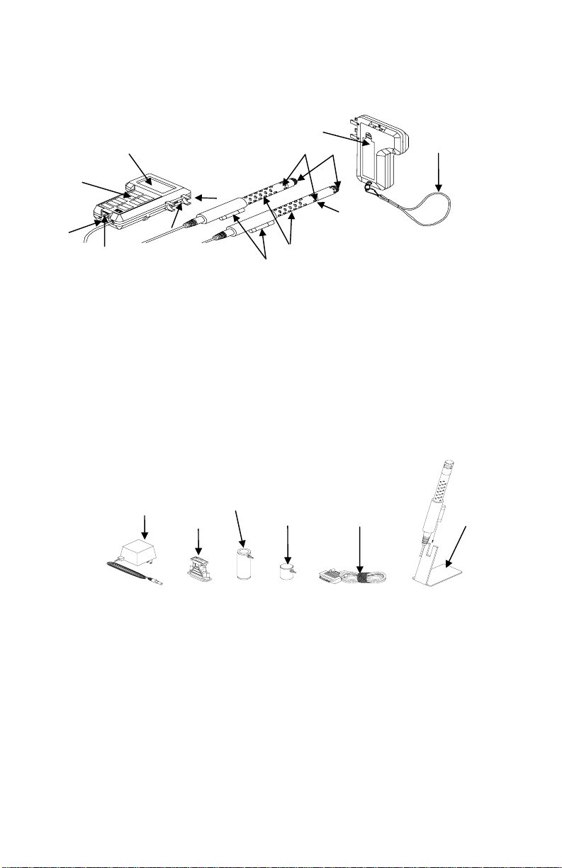
Parts Identification for the Q-T
Figures 1–1 and 1–2 identify the parts of the Q-T
RAK
RAK IAQ Monitor. Please
become familiar with these components before proceeding.
11
1
7
8
12
Model 8550
2
5
13
3
6
4
Figure 1–1: Q-T
10
9
Model 8551
RAK
1. Display 7. Location of Humidity Sensor
2. Keypad 8. Location of Temperature Sensor
3. External Power Socket 9. Location of CO
Sensor
2
4. Data Port RS-232 10. Probe Handle
5. Probe Mounting Clips 11. Battery Access Cover
6. Display/Keypad Lockout 12. Wrist Strap
Switch 13. Location of CO Sensor
(model 8551 only)
1
2
3
6
4
5
Figure 1–2: Q-T
RAK Accessories
1. AC Adapter 4. Computer Interface Cable
2. 25-Pin to 9-Pin Adapter 5. Probe Stand
Calibration Collar 6. CO Calibration adapter
3. CO
2
(Model 8551 Only)
Chapter 1
2

Chapter 2
Setting-Up
Supplying Power to the Q-T
The Q-T
RAK IAQ Monitor must be powered in one of two ways: four size
AA batteries or the supplied AC Adapter.
Installing the Batteries
Insert four size AA batteries as indicated by the diagram located on the
inside of the battery compartment. TSI ships the Q-T
batteries. NiCd rechargeable batteries may also be used.
Using the AC Adapter
The AC Adapter allows you to power the Q-T
outlet. When using the AC adapter, the batteries (if installed) will be
bypassed. The AC adapter is not a battery charger and will not charge
NiCd batteries.
The Q-T
RAK has an internal, non-user accessible battery that is used to
keep memory intact when power is turned off. Changing the AA-size
batteries or disconnecting the AC adapter will not cause data to be lost.
This battery is designed to last for years. TSI will install a new battery,
if necessary, when the unit is returned to the factory for service.
Instrument Setup
The Q-T
RAK comes with special software called TRAKPRO, which is
designed to provide you with maximum flexibility and power when using
the Q-T
RAK. The following sections describe how to install the software and
setup the computer.
Setting-up T
RAKPRO software contains a very comprehensive Help Function. This
T
RAKPRO Data Analysis Software
utility provides all the necessary information to guide you in all aspects
of software operation.
Connecting the Q-T
Each Q-T
RAK comes equipped with an RS-232 cable and a 25-pin to
9-pin serial cable adapter. One end of the cable is a 25-pin D
subminiature connector labeled COMPUTER; the other end is an RJ-45
modular connector that mates with the logging instrument. Serial port
connectors always have pins (male) on the computer side.
RAK
RAK with alkaline
RAK from an AC wall
RAK to a Computer
3
1. Locate an available serial port on your computer: COM1, COM2,
COM3, or COM4.
2. If the port has a 25-pin connector, you do not need the adapter. If
the port has a 9-pin connector, plug the 25-pin end of the adapter
into the RS-232 cable.
Connect the RS-232 cable to the available serial port on your
3.
computer.
Connect the RJ-45 connector to the Q-TRAK.
4.
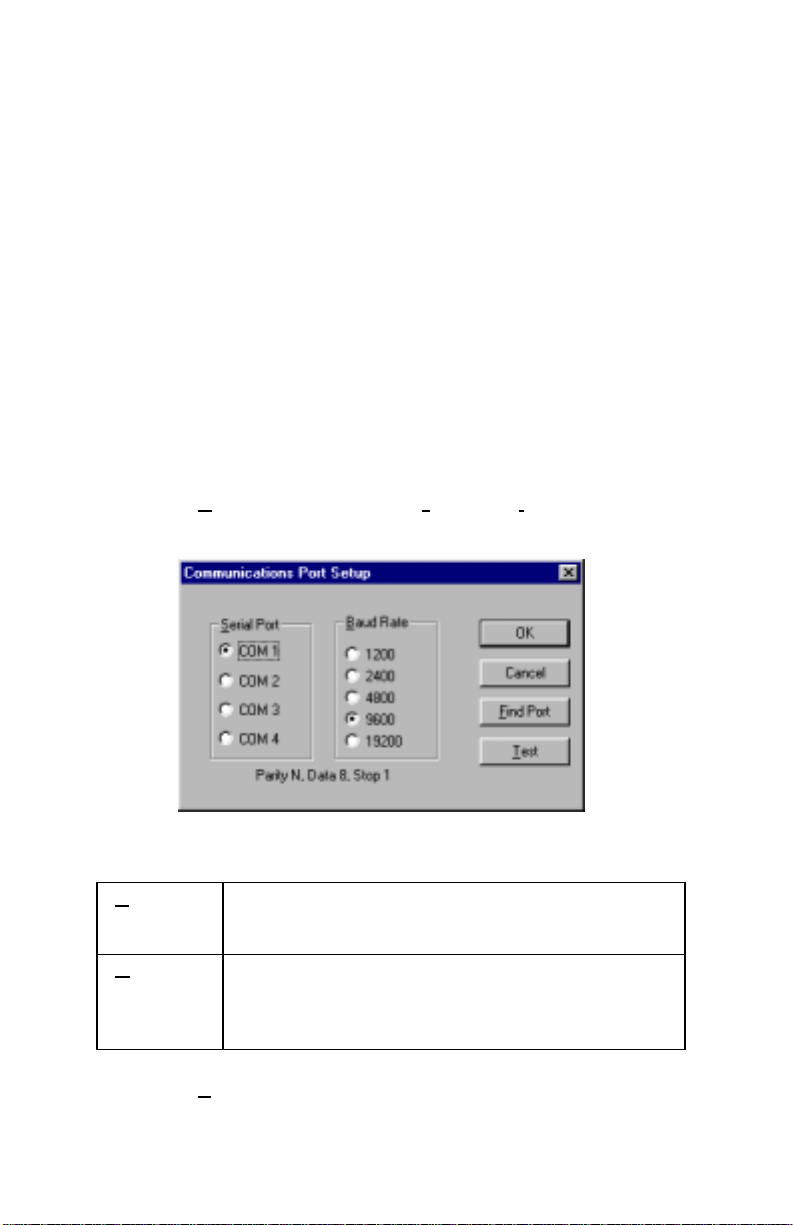
Set-Up the Communications Port
To communicate with the Q-T
the proper COM port. T
specific COM port, or it can automatically find a Q-T
RAK, the software must be configured for
RAKPRO can be manually set to operate on a
RAK that is
attached to any COM port. To set up the COM port, do the following:
1. Turn on the Q-T
2. Select C
following dialog is displayed:
Select the fo llowing:
3.
erial
S
Port
Baud
Rate
RAK and start TRAKPRO.
ommunications from the Instrument Setup menu. The
Select the name of the serial port to which the
logging device is connected: COM1, COM2, COM3,
or COM4.
Select the baud rate for the port. Higher baud rates
are recommended to transfer data at a faster rate.
Select a lower baud rate only if you are having
trouble communicating at a higher rate.
4. Select Test to verify that you have set up the communications port
properly. The system displays an informative message indicating
whether it was able to establish communications.
Chapter 2
4
5. As an alternate, you may select F
ind Port, to have TRAKPRO
search the available COM ports, looking for an attached Q-T
RAK.
6. Select
OK to accept the setup or Cancel to discard the changes.
Note: Some computers do not communicate reliably at baud rates
above 9600.
Setting the Real-Time Clock
The Q-T
RAK has an internal real-time clock that keeps track of the time
of day (the format is HH:MM where HH is the hour in 24-hour format
and the MM is minutes) and the date. It is very important for the
RAK to have the time and date correctly set; otherwise, date and time
Q-T
stamping of recorded data and calibrations will not be correct.
There are two ways to set the time and date. The first is to use the
supplied T
RAKPRO Data Analysis Software.
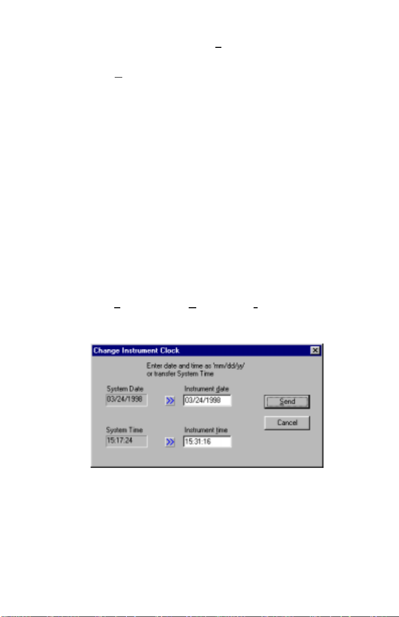
Programming the Date/Time Using TrakPro
To program the Q-T
1. Make sure the Q-T
2.
Select Parameters, then Clock from the Instrument Setup menu.
RAKPRO retrieves the current date and time settings from Q-TRAK
T
RAK date and time:
RAK is connected to the computer and turned on.
and displays them in the following dialog:
3. The system date and time (from the computer) may be transferred
to the Q-T
RAK using the “arrows” keys. Alternately, the date and
time may be manually entered into the dialog box.
4. Select Send to reprogram the Q-T
RAK.
5

Manually Setting the Real-Time Clock
To set the time and date with the keypad, you must press and hold the
SAMPLE key down while the Q-T
its power-up sequence. Release when the Q-T
RAK displays the time of day during
RAK “beeps.” You will
have an opportunity to view and/or change the hours, minutes, year,
month and day of month in sequence. Use the up and down arrow keys
(!") to change a setting. Use the SAMPLE key to store each setting
and advance to the next one.
Using the Probe Stand
For your convenience, the Q-T
RAK is supplied with a probe stand so
that the probe can be located above a table surface while unattended. To
use it, simply detach the probe from the Q-T
RAK mounting clips and
slide it onto the stand.
Connecting the Optional Model 8925 Portable Printer
To connect the Model 8925 printer to the Q-T
RAK, locate the Printer
Interface cable (supplied with optional printer) and connect the 9-pin
end labeled “PRINTER” to the printer and the other end to the data port
on the Q-T
RAK. Always turn the Q-TRAK on BEFORE the printer. If the
printer prints question marks (??????), asterisks (******), or random
characters, reset it by turning it off and then on again. If necessary, refer
to the Model 8925 Portable Printer Operation and Service Manual.
Chapter 2
6

Chapter 3
Operation
Overview
The Model 8550 and Model 8551 Q-T
temperature, and relative humidity. In addition the Model 8551 also
measures CO concentration. All parameters are measured simultaneously in
a single probe. The Q-T
RAK has four modes of operation, Survey, LOG 1,
LOG 2, and LOG 3. When the Q-T
mode which is used to display real-time readings and to determine statistics
such as average, minimum, and maximum readings. LOG 1 mode is used to
record individual data points for later analysis using a factory set protocol.
LOG 2 and LOG 3 modes have user-defined protocols, set up using
RAKPRO software. TRAKPRO software is used for analysis of data taken in
T
any of the three LOG modes, but cannot be used on samples taken in Survey
mode.
Keypad Functions
When pressing the keys on the front panel, the Q-T
the function. If you press a key and the Q-T
does not allow that function during the selected sampling mode. To disable
the beep, refer to Appendix B: “Internal DIP Switch Settings.”
ON/OFF Key
Use the ON/OFF key to turn the Q-T
first turned on it goes through a preprogrammed power-up sequence that
includes an internal self-check. First, all displayable items will appear for a
few seconds. If a problem is detected, the display shows the message
“SERVICE” along with a number to indicate that the Q-T
servicing. Refer to Chapter 5: “Troubleshooting” for information regarding
service numbers. If the “SERVICE” message appears, the Q-T
until any key is pressed.
When the Q-T
RAK completes its internal self-check, it will display the
approximate percentage of battery life remaining. The Q-T
+ –
battery symbol
when the battery voltage becomes very low. After the
battery symbol appears, the Q-T
before displaying the message “LO” (for a few seconds) and then
automatically turning off. This feature is accurate for alkaline batteries only.
The percentage life remaining will not be accurate for NiCd batteries. The
battery symbol appears when battery voltage becomes low, but the Q-T
RAK IAQ monitors measure CO
RAK is first turned on it will be in Survey
RAK will beep to confirm
RAK does not beep, the Q-TRAK
RAK on and off. When the instrument is
RAK requires
RAK pauses
RAK displays the
RAK runs for approximately 60 minutes
,
2
RAK
7
 Loading...