

TSI Incorporated 3563 Operation And Service

Particle Instruments
Integrating Nephelometer
Operation and Service Manual
Model 3563
P/N 1933563, Revision F
December 2005


Product Overview 1
Model 3563
Integrating Nephelometer
Operation and Service Manual
December 2005
Unpacking and
Setting Up the
Hardware
Operations Overview
Using NephLog
Software
Using Nephelometer
Software
Using Serial Data
Commands
2
3
4
5
6
Theory of Operation 7
Performing
8
Maintenance
Contacting
9
Customer Service
Appendixes

Manual History
The following is a history of the Model 3563 Integrating
Nephelometer Instruction Manual, part number 1933563.
Revision Date
Preliminary February 1994
Preliminary 1 August 1994
Preliminary 2 September 1994
Final November 1994
A May 1996
B April 1997
B1 July 1998
C December 2000
D April 2001
E October 2002
F December 2005
This manual was first published, in preliminary form, February
1994.
This manual was published as a preliminary 1 in August 1994.
This manual was published as a preliminary 2 in September
1994, additions of text and figures were made throughout
manual, Chapter 5 was added, and Chapter 8, “Troubleshooting
Guide,” was deleted.
The manual was published as a Final after Chapter 5, “Using
Nephelometer Software (Windows)” was added in November
1994.
In revision A, TSI’s “Limitation of Warranty and Liability” on
page iii was updated.
In revision B, Tables A-1 and A-2 in Appendix A were revised.
In revision B1, TSI’s area code changed from 612 to 651.
In revision C, TSI’s Limitation of Warranty and Liability and
TSI’s Software License were updated.
In revision D, Analog Outputs were removed.
In revision E, TSI’s phone numbers and address were updated
and schematics were removed from manual.
In revision F, Model 3550/3560 Series was changed to
Model 3563. Instructions were added for NephLog software and
Nephelometer software information was updated.
iv

Warranty
Part Number 1933563 / Revision F / December 2005
Copyright ©TSI Incorporated / 1994–2005 / All rights reserved.
Address TSI Incorporated / 500 Cardigan Road / Shoreview, MN 55126 / USA
Fax No. (651) 490-3824
Email Address particle@tsi.com
Limitation of Warranty
and Liability
(effective July 2000)
Seller warrants the goods sold hereunder, under normal use and service as
described in the operator's manual, shall be free from defects in workmanship and
material for (12) months, or the length of time specified in the operator's manual,
from the date of shipment to the customer. This warranty period is inclusive of any
statutory warranty. This limited warranty is subject to the following exclusions:
a. Hot-wire or hot-film sensors used with research anemometers, and certain other
components when indicated in specifications, are warranted for 90 days from
the date of shipment.
b. Parts repaired or replaced as a result of repair services are warranted to be free
from defects in workmanship and material, under normal use, for 90 days from
the date of shipment.
c. Seller does not provide any warranty on finished goods manufactured by others
or on any fuses, batteries or other consumable materials. Only the original
manufacturer's warranty applies.
d. Unless specifically authorized in a separate writing by Seller, Seller makes no
warranty with respect to, and shall have no liability in connection with, goods
which are incorporated into other products or equipment, or which are modified
by any person other than Seller.
The foregoing is IN LIEU OF all other warranties and is subject to the LIMITATIONS
stated herein. NO OTHER EXPRESS OR IMPLIED WARRANTY OF FITNESS FOR
PARTICULAR PURPOSE OR MERCHANTABILITY IS MADE.
TO THE EXTENT PERMITTED BY LAW, THE EXCLUSIVE REMEDY OF THE USER
OR BUYER, AND THE LIMIT OF SELLER'S LIABILITY FOR ANY AND ALL LOSSES,
INJURIES, OR DAMAGES CONCERNING THE GOODS (INCLUDING CLAIMS BASED
ON CONTRACT, NEGLIGENCE, TORT, STRICT LIABILITY OR OTHERWISE) SHALL
BE THE RETURN OF GOODS TO SELLER AND THE REFUND OF THE PURCHASE
PRICE, OR, AT THE OPTION OF SELLER, THE REPAIR OR REPLACEMENT OF THE
GOODS. IN NO EVENT SHALL SELLER BE LIABLE FOR ANY SPECIAL,
CONSEQUENTIAL OR INCIDENTAL DAMAGES. SELLER SHALL NOT BE
RESPONSIBLE FOR INSTALLATION, DISMANTLING OR REINSTALLATION COSTS
OR CHARGES. No Action, regardless of form, may be brought against Seller more
than 12 months after a cause of action has accrued. The goods returned under
warranty to Seller's factory shall be at Buyer's risk of loss, and will be returned, if at
all, at Seller's risk of loss.
Buyer and all users are deemed to have accepted this LIMITATION OF WARRANTY
AND LIABILITY, which contains the complete and exclusive limited warranty of
Seller. This LIMITATION OF WARRANTY AND LIABILITY may not be amended,
modified or its terms waived, except by writing signed by an Officer of Seller.
v

Software License (effective March 1999)
1. GRANT OF LICENSE. TSI grants to you the right to use one copy of the enclosed
TSI software program (the “SOFTWARE”), on a single computer. You may not
network the SOFTWARE or otherwise use it on more than one computer or
computer terminal at the same time.
2. COPYRIGHT. The SOFTWARE is owned by TSI and is protected by United States
copyright laws and international treaty provisions. Therefore, you must treat the
SOFTWARE like any other copyrighted material (e.g., a book or musical recording)
except that you may either (a) make one copy of the SOFTWARE solely for backup
or archival purposes, or (b) transfer the SOFTWARE to a single hard disk provided
you keep the original solely for backup or archival purposes.
3. OTHER RESTRICTIONS. You may not rent or lease the SOFTWARE, but you
may transfer the SOFTWARE and accompanying written material on a permanent
basis, provided you retain no copies and the recipient agrees to the terms of this
Agreement. You may not reverse-engineer, decompile, or disassemble the
SOFTWARE.
4. DUAL MEDIA SOFTWARE. If the SOFTWARE package contains multiple types of
media, then you may use only the media appropriate for your single-user
computer. You may not use the other media on another computer or loan, rent,
lease, or transfer them to another user except as part of the permanent transfer
(as provided above) of all SOFTWARE and written material.
5. U.S. GOVERNMENT RESTRICTED RIGHTS. The SOFTWARE and
documentation are provided with RESTRICTED RIGHTS. Use, duplication, or
disclosure by the Government is subject to the restrictions set forth in the “Rights
in Technical Data and Computer Software” Clause at 252.227-7013 and the
“Commercial Computer Software - Restricted Rights” clause at 52.227-19.
6. LIMITED WARRANTY. TSI warrants that the SOFTWARE will perform
substantially in accordance with the accompanying written materials for a period
of ninety (90) days from the date of receipt.
7. CUSTOMER REMEDIES. TSI’s entire liability and your exclusive remedy shall
be, at TSI’s option, either (a) return of the price paid or (b) repair or replacement of
the SOFTWARE that does not meet this Limited Warranty and which is returned
to TSI with proof of payment. This Limited Warranty is void if failure of the
SOFTWARE has resulted from accident, abuse, or misapplication. Any
replacement SOFTWARE will be warranted for the remainder of the original
warranty period or thirty (30) days, whichever is longer.
8. NO OTHER WARRANTIES. TSI disclaims all other warranties, either express or
implied, including, but not limited to implied warranties of merchantability and
fitness for a particular purpose, with regard to the SOFTWARE and the
accompanying written materials.
9. NO LIABILTY FOR CONSEQUENTIAL DAMAGES. In no event shall TSI be liable
for any damages whatsoever (including, without limitation, special, incidental,
consequential or indirect damages for personal injury, loss of business profits,
business interruption, loss of information or any other pecuniary loss) arising out
of the use of, or inability to use, this SOFTWARE.
Service Policy Knowing that inoperative or defective instruments are as detrimental to TSI as they
are to our customers, our service policy is designed to give prompt attention to any
problems. If any malfunction is discovered, please contact your nearest sales office
or representative, or call TSI’s Particle Instruments at 1-800-874-2811 (USA) or (651)
490-2811.
vi Model 3563 Integrating Nephelometer
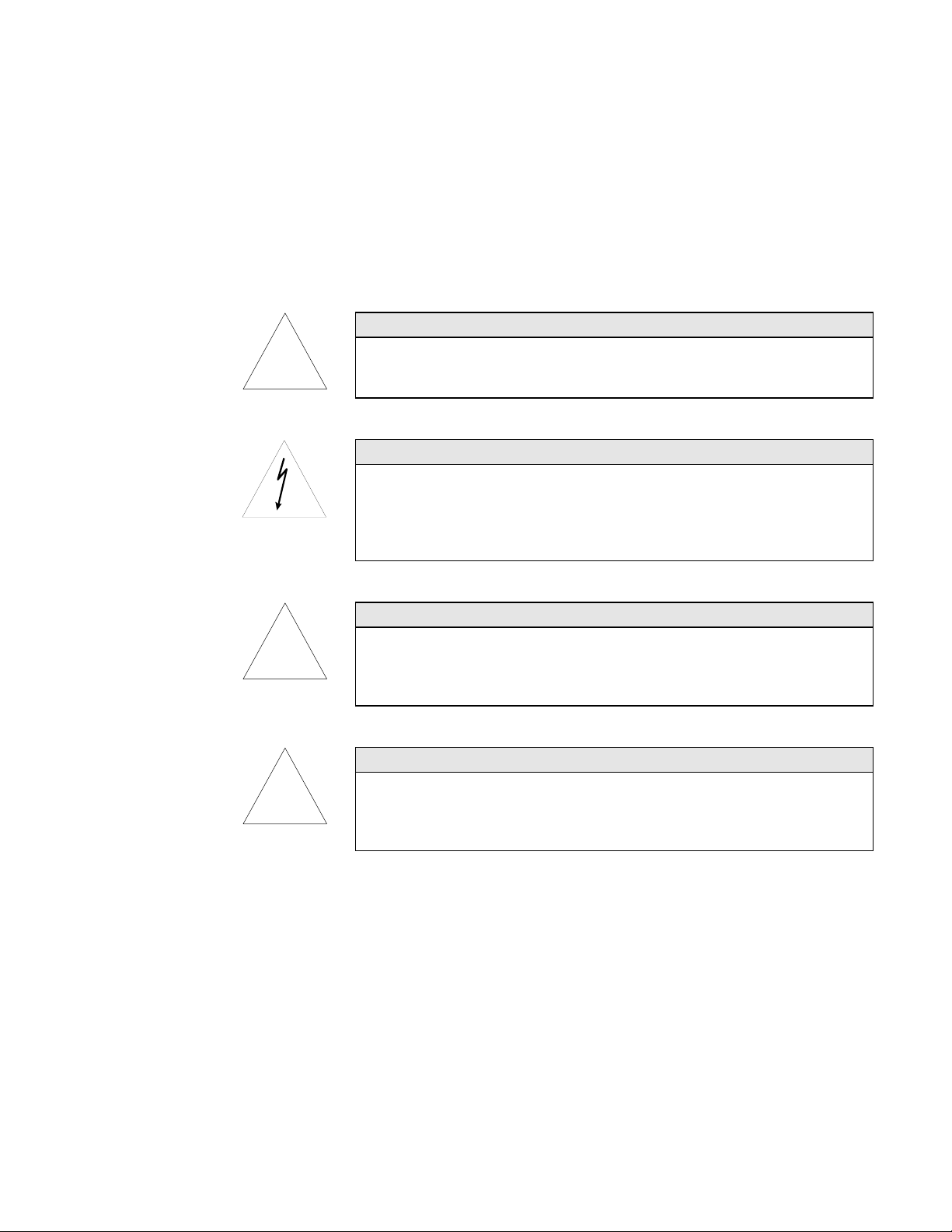
!
!
!
Safety
This section gives instructions to promote safe and proper handling
of the Model 3563 Integrating Nephelometer.
Caution
High temperatures that can cause burns.
To avoid personal injury, disconnect power to the Nephelometer and allow the
halogen lamp and the lamp housing to cool before handling.
WARNING
High voltages that can shock or burn.
The box that houses the photomultiplier tubes (PMT) contains a high voltage
source. Components within this box should only be serviced by a qualified
technician. Disconnect all power to the Nephelometer and contact TSI personnel
before disassembling the PMT box.
Caution
Light sensitive components.
To avoid damage to the photomultiplier tubes (PMT), remove power from the
Nephelometer and open the PMT box in subdued lighting. Exposing the
photomultiplier tubes to direct light may affect tube performance.
WARNING
Moving parts that can cause serious personal injury.
Disconnect power to Nephelometer before inserting anything into the aerosol
inlet. The ball valve and position sensor are motorized and can move if power is
applied.
vii
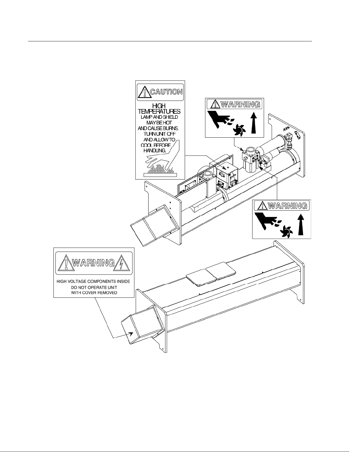
Labels
Figure 1 shows the special warning and caution labels and their
approximate location inside the Nephelometer.
Figure 1
Nephelometer Warning and Caution Labels
viii Model 3563 Integrating Nephelometer

Contents
Manual History .................................................................... iv
Warranty................................................................................v
Software License (effective March 1999) ................................ vi
Safety ................................................................................. vii
Labels ..................................................................................
About This Manual .............................................................xvii
Purpose...............................................................................
Reusing and Recycling ........................................................ xvii
Submitting Comments ........................................................ xvii
Notational Conventions ...................................................... xviii
viii
xvii
Chapters/Appendixes
CHAPTER 1 Product Overview............................................ 1-1
Product Description ............................................................ 1-1
Applications ........................................................................ 1-1
Beer-Lambert Law ............................................................ 1-2
How the Nephelometer Operates ......................................... 1-2
CHAPTER 2 Unpacking and Setting Up the Hardware ......... 2-1
Packing List ........................................................................ 2-1
Unpacking Instructions....................................................... 2-2
Connecting Power ............................................................... 2-2
Connecting Line Voltage to the Power Supply Module....... 2-2
Connecting the Power Supply Module to the
Nephelometer ................................................................ 2-
Using Another Power Supply ............................................ 2-3
Connecting a Computer ...................................................... 2-4
Mounting the Nephelometer ................................................ 2-4
Space Requirements......................................................... 2-6
Mounting Holes ................................................................ 2-6
Inlet and Outlet Ports ....................................................... 2-7
Environmental Concerns .................................................. 2-7
Connecting an External Blower ........................................... 2-8
Calibrating the Nephelometer .............................................. 2-9
3
CHAPTER 3 Operations Overview ....................................... 3-1
Serial Communications ....................................................... 3-
Hardware Components........................................................ 3-1
Power Failures ................................................................. 3-2
Lamp Power ..................................................................... 3-2
1
ix

Photomultiplier Tubes (PMTs)........................................... 3-2
Heater .............................................................................. 3-3
Blower Settings ................................................................ 3-3
Humidity and Temperature Sensors ................................. 3-3
Setting Up Parameters ........................................................ 3-4
Operating Parameters....................................................... 3-4
Time Parameters .............................................................. 3-7
Polled and Unpolled Communications .............................. 3-8
CHAPTER 4 Using NephLog Software ..................................4-1
Overview of NephLog Software............................................. 4-
1
Hardware and Software Requirements ................................ 4-1
Installing the NephLog Software .......................................... 4-2
Setting up the NephLog Software......................................... 4-4
CHAPTER 5 Using Nephelometer Software ..........................5-1
Overview of Nephelometer Software ..................................... 5-
1
Hardware and Software Requirements ................................ 5-2
Installing and Starting the Software .................................... 5-2
Quick Start ......................................................................... 5-4
Step 1. Verify COM Port .................................................. 5-5
Step 2. Start Data Collection ........................................... 5-5
Step 3. View Data and Nephelometer Status.................... 5-6
Step 4. Print a Graph ...................................................... 5-9
Step 5. Perform a Background (Zero Baseline)
Measurement ................................................................ 5-
9
Basic Nephelometer Operations...................................... 5-10
Clean Air Test ................................................................... 5-12
Menus and Commands: A Reference Guide ...................... 5-14
Using the File Menu ....................................................... 5-14
Using the Config Menu ................................................... 5-18
Using the View Menu ..................................................... 5-22
Using the Run Menu ...................................................... 5-35
Using the Window Menu................................................. 5-44
Using the Pause/Resume Menu ..................................... 5-44
Using the Help Menu...................................................... 5-45
CHAPTER 6 Using Serial Data Commands ........................... 6-1
Pin Connectors.................................................................... 6-
Baud Rate ........................................................................... 6-2
Parity (8-Bits Even) ............................................................. 6-2
Commands.......................................................................... 6-2
Set Commands................................................................. 6-5
Action Commands .......................................................... 6-18
Read Commands (Polled) ................................................ 6-21
Unpolled Commands ...................................................... 6-25
Unpolled Record Formats ............................................... 6-26
How to Input Commands and Troubleshoot the Results . 6-30
CHAPTER 7 Theory of Operation.........................................7-1
History ................................................................................ 7-
x Model 3563 Integrating Nephelometer
1
1

Construction ....................................................................... 7-2
Theory of Integration ........................................................... 7-4
Theory of Wavelength Dependence ...................................... 7-6
Signal Processing ................................................................ 7-8
Description....................................................................... 7-9
Equations/Calculations ................................................... 7-9
Detection Optics................................................................ 7-16
Calibration ........................................................................ 7-16
CHAPTER 8 Performing Maintenance ................................. 8-1
Removing Nephelometer Covers: Top, Bottom, and PMT ...... 8-
2
Removing the Top Cover ................................................... 8-2
Removing the Bottom Cover ............................................. 8-3
Removing the PMT Cover.................................................. 8-4
Calibrating the Nephelometer .............................................. 8-5
Cleaning Fan Filters............................................................ 8-6
Replacing the Main Microprocessor EPROM ........................ 8-7
Replacing the Motor Control Microprocessor ....................... 8-9
Replacing the Lamp........................................................... 8-
Replacing Aerosol Filters ................................................... 8-
11
13
Cleaning the Light Pipe Lens ............................................. 8-16
Checking for Leaks............................................................ 8-19
Cleaning the Reference Chopper........................................ 8-19
Cleaning the Light Pipe Outlet and the Backscatter
Shutter........................................................................... 8-
27
Cleaning the Flocked Paper ............................................... 8-35
Replacing a Temperature or Humidity Sensor ................... 8-40
Replacing a Photomultiplier Tube...................................... 8-42
Checking, Cleaning, and Replacing Bandpass Filters ........ 8-44
Cleaning the Lens ............................................................. 8-48
CHAPTER 9 Contacting Customer Service .......................... 9-1
Technical Contacts at TSI.................................................... 9-
1
Returning the Nephelometer for Service .............................. 9-1
APPENDIX A Specifications ................................................ A-1
APPENDIX B Bibliography .................................................. B-
Instrument Principles, Design and Calibration ................. B-
1
1
Applications of the Integrating Nephelometer to
Studies of Atmospheric Visibility ...................................B-
2
Light Scattering Measurements Related to Aerosol
Mass Concentration ...................................................... B-
3
Vertical Column and Horizontal Profile Studies with
the Integrating Nephelometer......................................... B-
4
Apportioning of Light Scattering Coefficient to
Chemical Species and to Sources .................................. B-
4
Use of the Integrating Nephelometer in Studies of
Physical and Chemical Properties of Aerosols ................B-
5
Observation of the Effects of Humidity on Light Scattering
Coefficient; Measurements on Fogs and Clouds ............. B-
Contents xi
6

Observation of Aerosols in Remote Locations with the
Integrating Nephelometer .............................................. B-
The Use of Integrating Nephelometer Data in Radiation
and Climate Studies ...................................................... B-
APPENDIX C Nephelometer Sensor Connectors ...................C-1
6
7
Figures
APPENDIX D Windows Program Files.................................. D-
Reader’s Comments
Index
1 Nephelometer Warning and Caution Labels ....................... viii
1-1 TSI Model 3563 Nephelometer .......................................... 1-
1-2 A Cross-Section View of the Nephelometer ........................ 1-
2-1 Power Supply Module ....................................................... 2-
2-2 Ventilation Requirements ................................................. 2-
2-3 COM Port Connector......................................................... 2-
2-4 Nephelometer Resting on its Feet...................................... 2-
2-5 Nephelometer in the Optimal Orientation ......................... 2-
2-6 As-Built Dimensions (Space Requirements) ...................... 2-
2-7 Blower Bracket ................................................................. 2-
2-8 Mounting the External Blower .......................................... 2-
3-1 Humidity and Temperature Sensor Locations ................... 3-
1
1
3
2
3
4
5
5
6
8
9
4
4-1 Start-up Screen ................................................................ 4-
4-2 Setup Options .................................................................. 4-
4-3 Selecting the Communications Port .................................. 4-
4-4 Communications Port Error .............................................. 4-
4-5 Open Data File Dialog....................................................... 4-
4-6 Data Display Options ....................................................... 4-
5-1 Start-up Screen ................................................................ 5-
5-2 The Main Menu of the Windows-Based Nephelometer
Program ........................................................................... 5-
5-3 The COM Port Setup Display ............................................ 5-
5-4 Choosing Data Collection from the Run Menu Starts
Data Collection................................................................. 5-
5-5 Select Data Display to View Data as it is Collected by
the Nephelometer ............................................................. 5-
5-6 The Nephelometer State Display Shows the Status of
the Nephelometer ............................................................. 5-
5-7 The Photon Frequency Display Shows the Current
Photon Frequency Calculations ........................................ 5-
5-8 The Graph Display Shows Current Data ........................... 5-
5-9 The Terminal Mode Display ............................................ 5-
3
4
5
6
8
9
3
4
5
6
7
7
8
8
10
xii Model 3563 Integrating Nephelometer

5-10 The Set Nephelometer Parameters Display Shows the
Current Parameters of the Nephelometer........................ 5-
5-11 Select a Filename After Choosing the Open Log File
Command ...................................................................... 5-
5-12 Select a Filename After Choosing the Log Data
Command ...................................................................... 5-
5-13 Select the Print Command from the File Menu................ 5-
5-14 Types of Graphs. Scatter Data Graph (top) and Status
Graph (bottom)............................................................... 5-
5-15 Choose Nephelometer from the Config Menu................... 5-
5-16 Use the COM Port Setup Display to Select the
Appropriate Communications Port ................................. 5-
5-17 The Data Display Shows Current (raw) Data Values
Collected by the Nephelometer ....................................... 5-
5-18 Graph Data of the Current Log Data File ........................ 5-
5-19 The Graph Options Window Lets You Customize Your
Graphs........................................................................... 5-
5-20 Photon Frequency Display .............................................. 5-
5-21 The Photon Frequency Graph Displays Current
Measurements................................................................ 5-
5-22 The Status of the Nephelometer is Displayed by Selecting
Neph State from the View Menu ..................................... 5-
5-23 Nephelometer Configuration Data is Displayed by
Selecting Neph Config Data from the View Menu ............ 5-
5-24 Display Log File Records in Tabular Format by Selecting
Log Data Table from the View Menu ............................... 5-
5-25 Select the Type of Graph from the Log Data Graph
Options .......................................................................... 5-
5-26 Operating Status Graph ................................................. 5-
5-27 Photon Counts (Calibrator) Graph .................................. 5-
5-28 Photon Counts (Dark) Graph .......................................... 5-
5-29 Photon Counts (Measure) Graph ..................................... 5-
5-30 Scattering Coefficients Graph ......................................... 5-
5-31 The Destination Dialog Box ............................................ 5-
5-32 The Nephelometer Calibration Data Display.................... 5-
5-33 Calibration Parameters Setup Screen ............................. 5-
5-34 Plugs for Inlet and Outlet and Gas Line With the Blue
DQ Filter ........................................................................ 5-
5-35 Selecting Data Collection from the Run Menu ................. 5-
5-36 Select Terminal Mode to Issue Serial Data Commands
to the Nephelometer ....................................................... 5-
5-37 The Help Contents Display Provides a List of Help
Topics ............................................................................ 5-
5-38 About Shows the Current Version of Your Software
and the Copyright Notice ................................................ 5-
13
15
16
17
18
19
22
23
25
25
27
27
28
29
31
32
33
33
33
34
34
35
36
37
42
43
44
45
46
6-1 COM Port Pin Designations............................................... 6-
6-2 Timelines for Data Measurement .................................... 6-
6-3 Comparison of Manual, Normal, and Air Chop Modes ..... 6-
Contents xiii
1
11
12

7-1 Nephelometer Schematic .................................................. 7-2
7-2 Reference Chopper Zones ................................................. 7-
7-3 Nephelometer Geometry.................................................... 7-
3
5
8-1 Nephelometer Showing Top, Bottom, and PMT Covers ...... 8-
8-2 Top Cover Screws, Bottom Cover Screws, Fan Cover Screws,
and I/O Panel Screws....................................................... 8-
8-3 PMT Cover ........................................................................ 8-
8-4 Fan Covers and Foam Inserts ........................................... 8-
8-5 Top Cover Screws ............................................................. 8-
8-6 Microprocessor and EPROM Locations on the Digital
Circuit Board ................................................................. 8-
8-7 Top Cover Screws ........................................................... 8-
8-8 Lamp Shield ................................................................... 8-
8-9 Top Cover Screws ........................................................... 8-
8-10 Bottom Cover Screws Securing End Plate ....................... 8-
8-11 White HEPA Filter........................................................... 8-
8-12 Blue DQ Filter ................................................................ 8-
8-13 Top Cover Screws ........................................................... 8-
8-14 Lamp Shield ................................................................... 8-
8-15 Light Pipe Lens ............................................................... 8-
8-16 Top Cover Screws, Bottom Cover Screws, Fan Cover
Screws, and I/O Panel Screws........................................ 8-
8-17 Circuit Board Mounting Screws ...................................... 8-
8-18 PMT End Plate Screws .................................................... 8-
8-19 Aperture Assembly ......................................................... 8-
8-20 Aperture Plates and Circuit Board .................................. 8-
8-21 Reference Chopper.......................................................... 8-
8-22 Top Cover Screws, Bottom Cover Screws, Fan Cover
Screws, and I/O Panel Screws........................................ 8-
8-23 Lamp Shield ................................................................... 8-
8-24 Disconnect Connectors and Tubing ................................ 8-
8-25 Nephelometer Sections Together ..................................... 8-
8-26 Nephelometer Sections Apart .......................................... 8-
8-27 Lamp Base ..................................................................... 8-
8-28 Removing the Lamp Base Assembly From the Sensor ..... 8-
8-29 Light Pipe Outlet and Backscatter Shutter ...................... 8-
8-30 O-ring on the Sensor Backbone ...................................... 8-
8-31 Top Cover Screws, Bottom Cover Screws, Fan Cover
Screws, and I/O Panel Screws........................................ 8-
8-32 Disconnect Connectors and Tubing ................................ 8-
8-33 Nephelometer Sections Together ..................................... 8-
8-34 Nephelometer Sections Apart .......................................... 8-
8-35 Flocked Paper Outside the Nephelometer........................ 8-
8-36 Top Cover Screws, Bottom Cover Screws, Fan Cover
Screws, and I/O Panel Screws........................................ 8-
8-37 Humidity and Temperature Sensor Locations ................. 8-
8-38 PMT Cover ...................................................................... 8-
8-39 Red, Blue and Green PMTs with Setscrews ..................... 8-
2
3
5
6
8
10
11
12
13
14
15
15
16
17
18
20
22
23
24
25
25
27
28
29
30
30
31
32
33
34
36
37
38
38
39
41
41
43
44
xiv Model 3563 Integrating Nephelometer

Tables
8-40 PMT Cover ...................................................................... 8-46
8-41 Red, Blue and Green PMTs with Setscrews ..................... 8-
8-42 Bandpass Filter .............................................................. 8-
8-43 PMT Cover ...................................................................... 8-
8-44 Red, Blue and Green PMTs with Setscrews ..................... 8-
2-1 Packing List with Accessories ........................................... 2-1
3-1 Typical Time Settings........................................................ 3-9
5-1 Basic Windows Nephelometer Operations ....................... 5-11
5-2 Nephelometer Setup Parameters ..................................... 5-20
5-3 Data Display Parameters ................................................ 5-23
5-4 Graph Options for the Graph Display ............................. 5-26
5-5 Nephelometer Configuration Data ................................... 5-30
5-6 Calibration Parameters ................................................... 5-37
5-7 Calibration Procedure ..................................................... 5-39
6-1 Signal Connections for RS-232 Configurations ................. 6-2
6-2 Serial Commands ............................................................. 6-4
47
48
49
50
7-1 Examples of Raw Count Data ........................................... 7-9
7-2 Comparisons Between Gate Width and Physical
Dimensions .................................................................... 7-
7-3 Counts Normalize to Photon Frequency (Hz) ................... 7-11
7-4 Boxcar Averages ............................................................. 7-11
8-1 Maintenance Overview...................................................... 8-1
A-1 Specifications for the Nephelometer Sensor ...................... A-1
10
Contents xv


About This Manual
Purpose
This is an operation and service manual for the Model 3563
Integrating Nephelometer.
Reusing and Recycling
As part of TSI Incorporated’s effort to have a minimal negative
impact on the communities in which its products are manufactured
and used:
This manual uses recyclable paper.
This manual has been shipped, along with the instrument, in a
reusable carton.
Submitting Comments
TSI values your comments and suggestions on this manual. Please
use the comment sheet, located on the last page of this manual, to
send us your opinion on the manual’s usability, to suggest specific
improvements, or to report any technical errors.
If the comment sheet has already been used, mail or fax your
comments on another sheet of paper to:
Particle Instruments
TSI Incorporated
500 Cardigan Road
Shoreview, MN 55126
Fax: (651) 490-3824
xvii

Notational Conventions
This manual uses the following conventions when describing
software:
<Enter> Denotes the “Return” or “Enter” key on the
keyboard.
<xx> Denotes an alphanumeric key on the keyboard. For
instance, <F4> means press the function “F4” on the
keyboard.
examples Examples of what you see on the screen and the text
you type are shown in monospace type resembling
computer output.
italic Variable information in computer responses,
commands, and options you must supply and type
are shown in italics in a font that resembles
computer font.
UPPERCASE Uppercase letters indicate names of programs, files
or commands.
Bold Bold type indicates names of fittings as they appear
on the instrument and commands appearing on the
display.
xviii Model 3563 Integrating Nephelometer
CHAPTER 1
Product Overview
This chapter contains a product description and a list of features
for the Model 3563 Integrating Nephelometer,
description of how the instrument works.
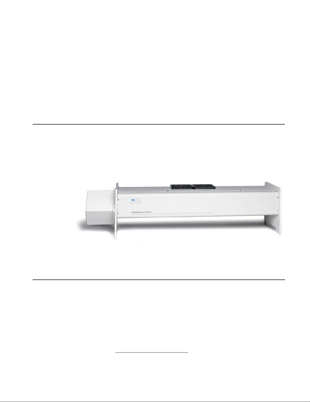
Product Description
The Model 3563 Integrating Nephelometer, shown in Figure 1-1, is
designed for long-term monitoring of visual range and air quality in
ground-based and airborne studies. It continuously monitors the
light scattering coefficient of airborne particles.
*
as well as a brief
Applications
Figure 1-1
TSI Model 3563 Nephelometer
TSI Integrating Nephelometer is designed specifically for studies of
direct radiative forcing of the Earth’s climate by aerosol particles, or
studies of ground-based or airborne atmospheric visual air quality
in clean areas. It may also be used as an analytical detector for
aerosol particles whenever the parameter of interest is the lightscattering coefficient of the particles after a pretreatment step, such
as heating, humidification, or segregation by size.
*
The design of this instrument incorporates developments patented by the University of
Washington. Refer to United States Patent Numbers 3,563,661; 3,700,333; and 3,953,127.
1-1

The light-scattering coefficient is a highly variable aerosol property.
Integrating Nephelometer measures the angular integral of light
scattering that yields the quantity called the scattering coefficient,
used in the Beer-Lambert Law to calculate total light extinction.
Beer-Lambert Law
I/Io = e
where:
I
= intensity of light source
o
I = intensity of light after passing through atmospheric path
x = thickness of medium through which light passes
σ
= total extinction coefficient
(= scattering coefficient + absorption coefficient)
(-σx)
How the Nephelometer Operates
A small, turbine blower draws an aerosol sample through the large
diameter inlet into the measurement volume (
the sample is illuminated over an angle of 7 to 170° by a halogen
lamp directed through an optical light pipe and opal glass diffuser.
Figure 1-2). There,
The sample volume is viewed by three photomultiplier tubes (PMT)
through a series of apertures set along the axis of the main
instrument body. Aerosol scattering is viewed against the backdrop
of a very efficient light trap. The light trap, apertures, and a highly
light-absorbing coating on all internal surfaces of the instrument
combine to give a very low scatter signal from the walls of the
instrument.
Dichroic filters, in front of the PMT tubes, split and direct the light,
which has been scattered by aerosol. The light is directed into three
bandpass filters, blue, green and red. A constantly rotating
reference chopper has separate areas to provide three types of
signal detection. The first area gives a measure of the aerosol lightscattering signal allowed by an opening in the rotating chopper. The
second area blocks all light from detection and gives a
measurement of the PMT dark current that which is subtracted
from the measurement signal. The third area is a translucent
portion of the chopper, illuminated by the halogen lamp, which
provides a measure of the light-source signal. In this way, over
time, any change in the light source or in detector efficiency is
compensated.
1-2 Model 3563 Integrating Nephelometer
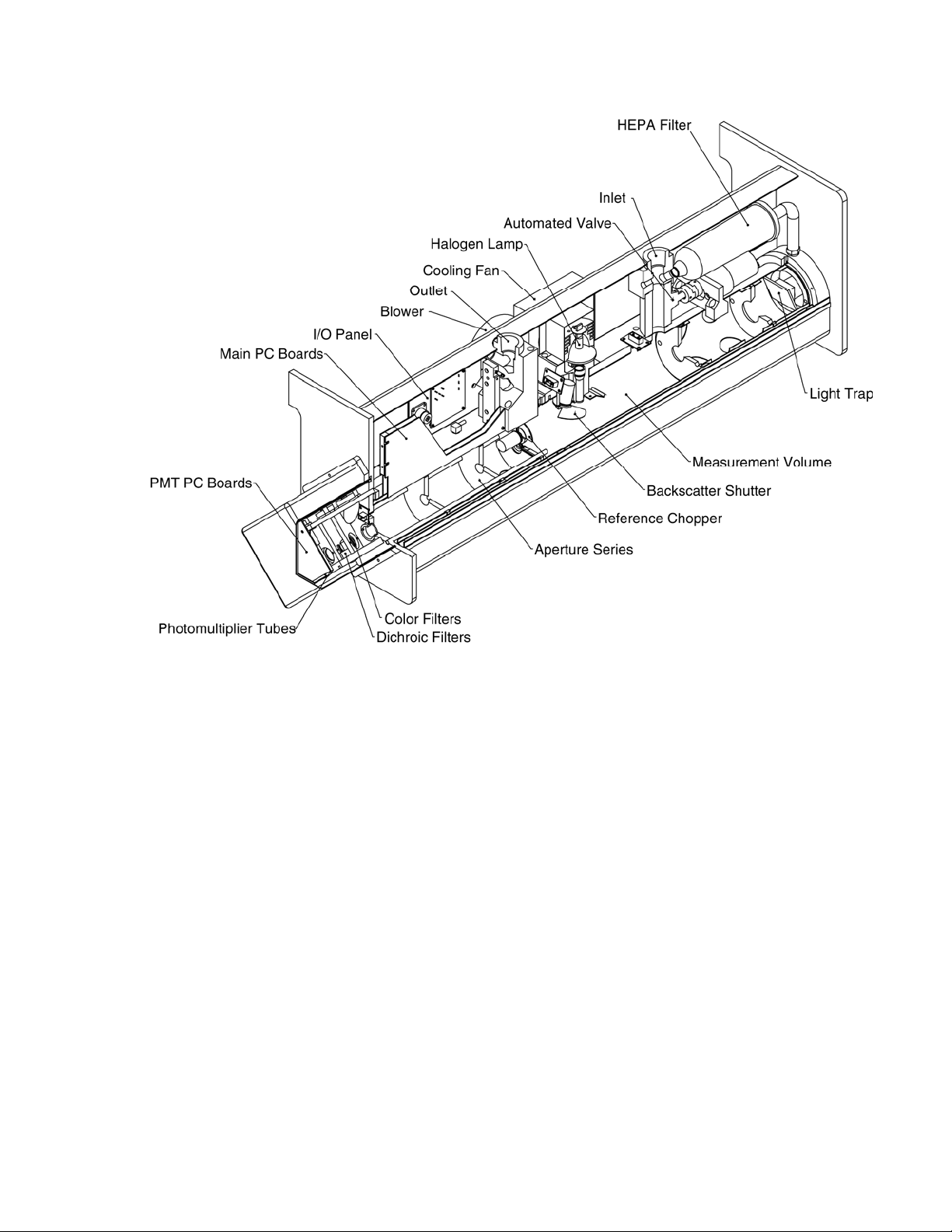
Figure 1-2
A Cross-Section View of the Nephelometer
In backscatter mode, the backscatter shutter rotates under the
lamp to block light in the 7 to 90° range. When light is blocked,
only light scattered in the backward direction is transmitted to the
PMT detectors. The backscatter signal can be subtracted from the
total signal to calculate forward-scattering signal data. When this
measurement is not of interest, the backscatter shutter can be
“parked” in the total scatter position.
Periodically, an automated valve built into the inlet can be activated
to divert all of the aerosol sample through a high-efficiency (HEPA)
filter. This gives a measure of the clean-air signal for the local
environment. This signal is subtracted, along with the PMT darkcurrent signal, from the aerosol-scatter signal to give only that
portion of the scatter signal provided by the sample aerosol.
Particle-scattering parameters for all three wavelengths of total and
backscatter signal are continuously averaged and passed to a
computer or data logger for permanent storage.
Product Overview 1-3


CHAPTER 2
Unpacking and Setting
Up the Hardware
Use the information in this chapter to unpack and set up the
hardware components of a Model 3563 Integrating Nephelometer.
This chapter contains these main sections:
Packing List
Unpacking instructions
Connecting power
Connecting a computer
Packing List
Mounting the Nephelometer
Connecting an external blower
Table 2-1 gives a packing list for the Nephelometer and the power
supply module. The packing list for the Data Analysis Center is
included in one of the two or three Data Analysis Center shipping
cartons.
Table 2-1
Packing List with Accessories
Qty Description Part Number
1 Nephelometer 3563
1 Power supply module 3590
1 Power supply cable 1303053*
1 Power cord (24 volts dc) 1035551
1 Blower bypass 1035545
1 Serial data cable (9-pin, 12 ft.) 962002
1 Serial cable adapter (25F-9M) 962003
1 Software CD 390107
1 Instruction manual 1933563
1 White HEPA filter 1602051
1 Blue DQ filter 1602080
1 Set (2) fan filters (foam inserts) 1602071
1 Lamp (halogen) 2201111
1 Vacuum grease 1701000
*Power cord listed is for USA use only.
2-1
Unpacking Instructions
The power supply module and power cord are in one box; the
Nephelometer sensor, power cable, manual, software CD, and other
accessories are in another box. Keep the packing material in case
you have to send the Nephelometer back to TSI.
The Nephelometer sensor comes fully assembled. If anything is
missing or appears to be damaged, contact your TSI representative,
or contact Customer Service at 1-800-874-2811 (USA) or (651) 490-
2811. Chapter 9, “
for returning the Nephelometer to TSI Incorporated.
Contacting Customer Service,” gives instructions
Connecting Power
This section describes connecting power to the power supply
module and connecting the power supply module to the
Nephelometer sensor, as well as using another power source for the
Nephelometer sensor.
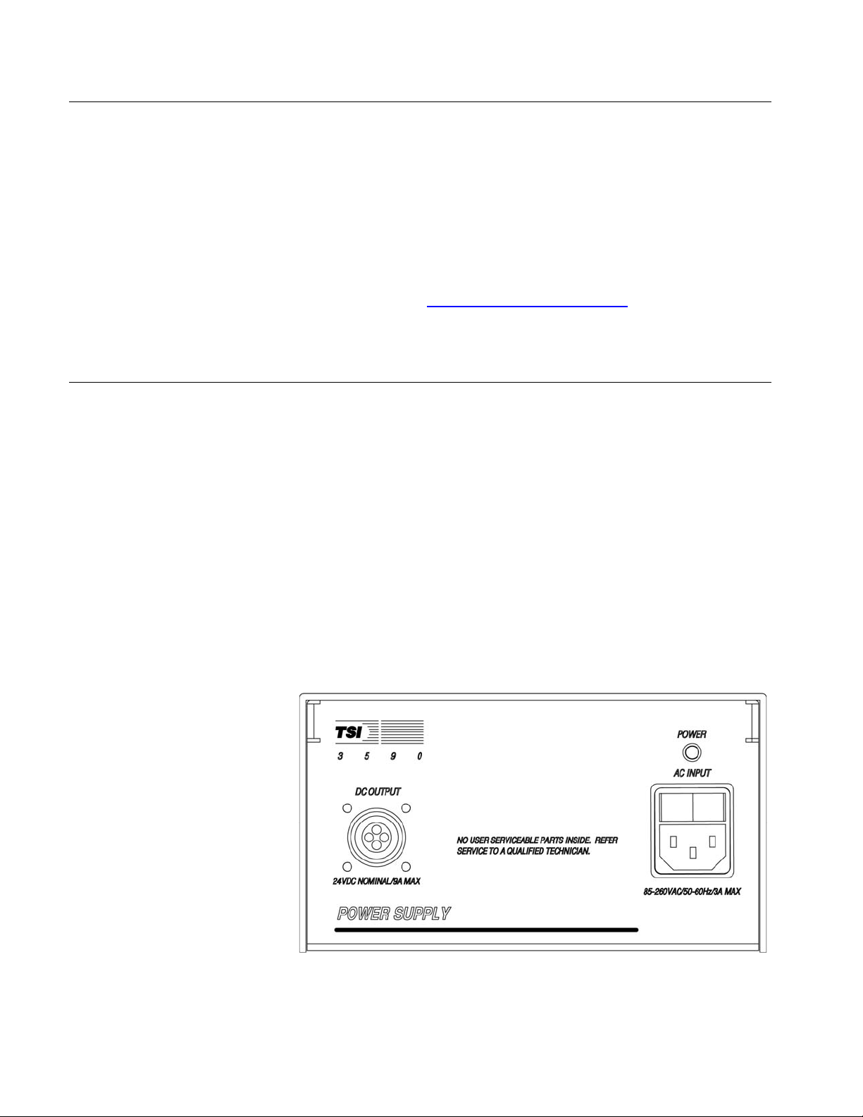
Connecting Line Voltage to the Power Supply Module
Use the line cord (supplied) to connect the TSI power supply
module to any line voltage from 85–260 volts AC at 50–60 Hz
(
Figure 2-1). The auto-switching power supply automatically
adjusts to the AC voltage provided.
Figure 2-1
Power Supply Module
2-2 Model 3563 Integrating Nephelometer
Connecting the Power Supply Module to the Nephelometer
The power supply module includes a 4-meter (12-ft.) cord with fourconductor, quarter-turn quick connectors. Before connecting the
cord, make sure the power switch is in the Off position. Connect
the pin end to the power supply and the socket end to the POWER
AC INPUT connector (
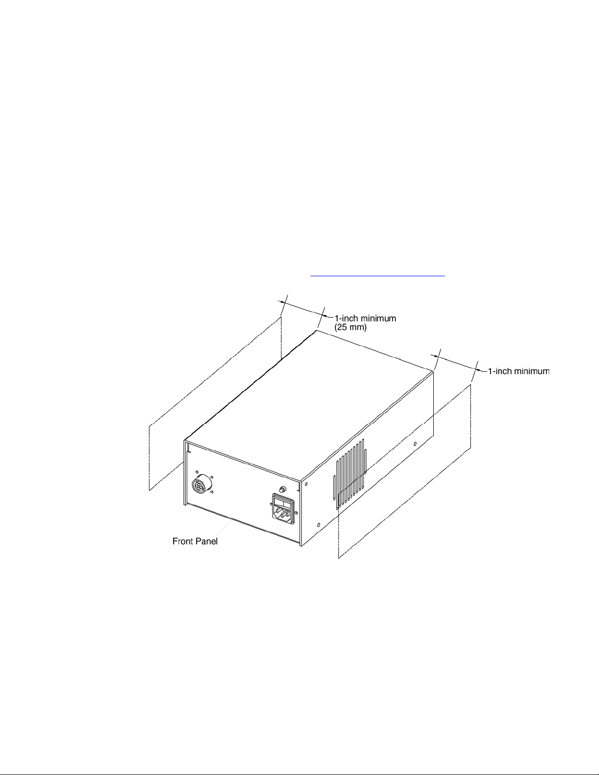
The TSI power supply module can be oriented in any direction, but
the cooling fan intake and exhaust vents should be free from
obstructions at all times (
Note: The power supply module contains no user-serviceable parts.
If the module is not operating properly, use the information in
Chapter 9, “
Figure 2-1) on the Nephelometer sensor.
Figure 2-2).
Contacting Customer Service,” to contact TSI.
Figure 2-2
Ventilation Requirements
Using Another Power Supply
As an option, you can connect the Nephelometer sensor to a 24–28
volts DC source. The lamp power is maximum at the higher end of
the DC range. You may order an extra cable (1035564) and wire
one end by connecting the red wire to +, the white wire to –, and the
green wire to chassis ground.
Unpacking and Setting Up the Hardware 2-3
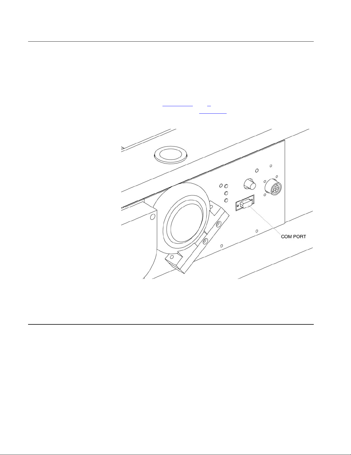
Connecting a Computer
Connect the serial port of an IBM-compatible computer to the
COM PORT connector on the Nephelometer sensor (
the 4-meter cable provided, and if you need additional length, use a
standard IBM 9-pin, serial extension cable.
Note: Refer to
software and refer to
data commands.
Chapters 4 and 5 for instructions on using TSI
Figure 2-3). Use
Chapter 6 for information on using serial
Figure 2-3
COM Port Connector
Mounting the Nephelometer
You can mount the Nephelometer in a variety of positions
depending on the application. Normally, the Nephelometer rests on
its feet (
the PMT box at the top and the light trap end at the bottom
(
Figure 2-5).
Note: Other positions are possible but consider dust collection
2-4 Model 3563 Integrating Nephelometer
Figure 2-4), but the best position is a vertical mount with
opposite the lamp or on the lens. Dust raises the background
noise level and necessitates cleaning more often.
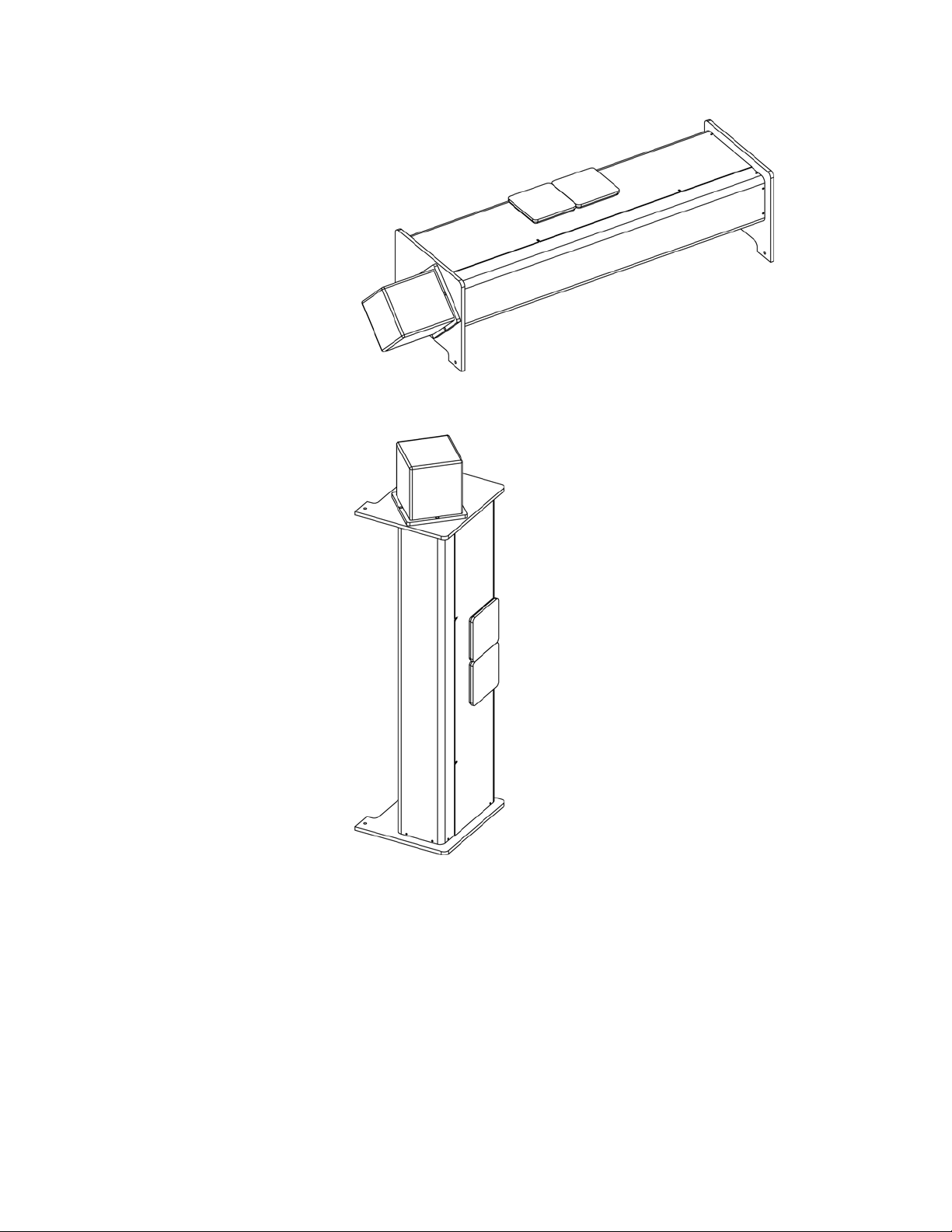
Figure 2-4
Nephelometer Resting on its Feet
Figure 2-5
Nephelometer in the Optimal Orientation
Unpacking and Setting Up the Hardware 2-5
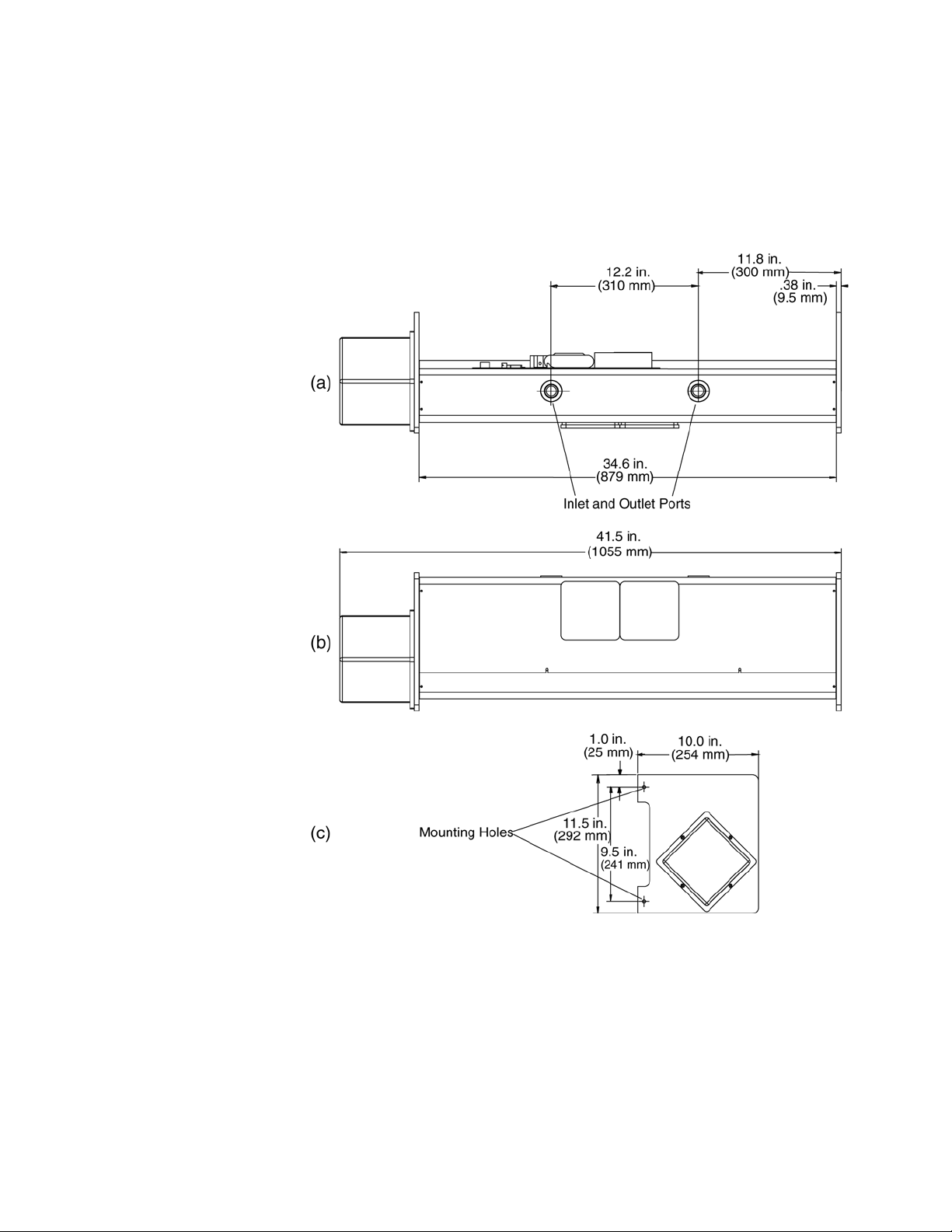
Space Requirements
The Nephelometer sensor requires a rectangular space (Figure 2-6).
You also need to allow room for the power supply module, air
ventilation, and a cable to reach the sensor. If you are using a
computer to set up the sensor, allow space for that as well.
Figure 2-6
As-Built Dimensions (Space Requirements)
Mounting Holes
Use the four mounting holes, two on each leg, to mount the
Nephelometer sensor (
bolts or screws to mount the instrument to a secure bracket, if
needed.
2-6 Model 3563 Integrating Nephelometer
Figure 2-6c). Use four 6 mm (¼ in.) diameter

Inlet and Outlet Ports
The inlet and outlet ports are 1 in. diameter female NPT (pipe
threaded) fittings (
adapters to mate to smaller or larger rigid tubing or can be fastened
directly to 1 in. pipe with a 1 in. NPT end. Rigid PVC tubing is often
used to bring a sample into the instrument and to exhaust the
sample from the instrument.
Keep in mind that the inlet and outlet tubing should have at least
8 inches of straight length to allow the cover to be easily removed
for maintenance.
Figure 2-6a). These fittings can be used with
Environmental Concerns
The Nephelometer is a highly sensitive instrument that detects
light-scattering from air (gas) molecules and particles present in the
sample chamber. The Nephelometer also detects undesirable
scatters from insects, birds, and rodents that may come into the
sampling chamber. Pests can severely limit the Nephelometer’s
ability to measure scattering from particles.
One way to minimize pests is to use insect screens, fly, or insect
traps in the upstream sampling line to prevent insects or small
pests from coming into the sampling chamber. Use metal screens to
prevent larger pests from coming into the sampling chamber.
It is good to keep in mind that humidity above 50–70% will enhance
scattering extinction (normally assumed to be small) by particles.
You may want to consider a heater or desiccant on the inlet flow to
keep the humidity below this level. Although the Nephelometer
incorporates a heater in the body, this is intended to compensate
for any cooling effects of the instrument body. It is not intended to
reduce the humidity through the instrument.
If the instrument will be used to sample from a warm, moist
environment, while located in a cooled enclosure, you should
consider insulating the inlet tubing and using the Nephelometer
heater feature (see H command in
In designing the inlet and plumbing systems, be aware that
changes in building pressure or a venturi effect caused by high
winds, can cause flow changes and reversals through the
Nephelometer.
Note: Minimize flow restrictions and particle loss when taking these
measures.
Chapter 6).
Unpacking and Setting Up the Hardware 2-7
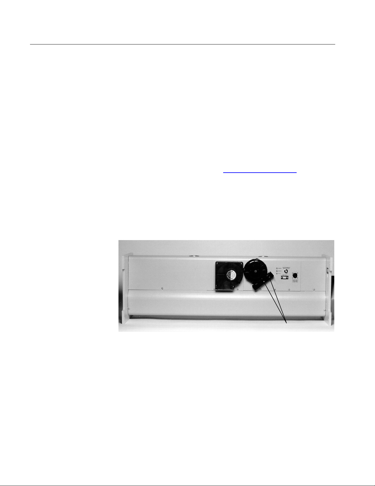
Connecting an External Blower
)
You can use the Nephelometer with an external blower to move the
sample though the instrument. If you use an external blower, you
can remove the onboard blower and replace it with the blower
bypass fitting to reduce pressure drop through the sampling
volume.
Note: You need custom software to control the external blower. As of
this date, TSI software does not include an interface to control
an external blower.
To remove the onboard blower and install the external blower:
1. Remove the top cover of the Nephelometer using the
instructions in Chapter 8, "
2. Remove the two screws attaching the blower bracket to the
Nephelometer (
3. O-ring seals on the ports hold the blower in place. Firmly pull
the blower away from the mounting plate.
4. Insert the blower bypass fitting into the pair of holes previously
occupied by the blower.
Figure 2-7).
Performing Maintenance."
Figure 2-7
Blower Bracket
5. Install the external blower bypass fitting by pressing it into the
hole in the mounting plate (
blower bracket.
2-8 Model 3563 Integrating Nephelometer
Blower Bracket Screws (2
Figure 2-8) and reattaching the
 Loading...