

Page 1

VOLATILE ORGANIC COMPOUND
PROBES
MODELS 984, 985, 986 AND 987
OPERATION AND SERVICE MANUAL
P/N 6007661, REVISION A
FEBRUARY 2014
Page 2

Page 3

Copyright
TSI Incorporated / 2014 / All rights reserved.
Address
TSI Incorporated / 500 Cardigan Road / Shoreview, MN 55126 / USA
Fax No.
(651) 490-3824
LIMITATION OF WARRANTY AND LIABILITY (effective June 2011)
(For country-specific terms and conditions outside of the USA, please visit www.tsi.com.)
Seller warrants the goods sold hereunder, under normal use and service as described in
the operator's manual, shall be free from defects in workmanship and material for 24
months, or if less, the length of time specified in the operator's manual, from the date of
shipment to the customer. This warranty period is inclusive of any statutory w arranty . This
limited warranty is subject to the following exclusions and exceptions:
a. Hot-wire or hot-film sensors used with research anemometers, and certain other
components when indicated in specifications, are warranted for 90 days from the date
of shipment;
b. Pumps are warranted for hours of operation as set forth in product or operator’s
manuals;
c. Parts repaired or replaced as a result of repair services are warranted to be free from
defects in workmanship and material, under normal use, for 90 days from the date of
shipment;
d. Seller does not provide any warranty on finished goods manufactured by others or on
any fuses, batteries or other consumable materials. Only the original manufacturer's
warranty applies;
e. Unless specifically authorized in a separate writing by Seller, Seller makes no warranty
with respect to, and shall have no liability in connection with, goods which are
incorporated into other products or equipment, or which are modified by any person
other than Seller.
The foregoing is IN LIEU OF all other warranties and is subject to the LIMITATIONS stated
herein. NO OTHER EXPRESS OR IMPLIED WARRANTY OF FITNESS FOR
PARTICULAR PURPOSE OR MERCHANTABILITY IS MADE. WITH RESPECT TO
SELLER’S BREACH OF THE IMPLIED WARRANTY AGAINST INFRINGEMENT, SAID
WARRANTY IS LIMITED TO CLAIMS OF DIRECT INFRINGEMENT AND EXCLUDES
CLAIMS OF CONTRIBUTORY OR INDUCED INFRINGEMENTS. BUYER’S EXCLUSIVE
REMEDY SHALL BE THE RETURN OF THE PURCHASE PRICE DISCOUNTED FOR
REASONABLE WEAR AND TEAR OR AT SELLER’S OPTION REPLACEMENT OF
THE GOODS WITH NON-INFRINGING GOODS.
TO THE EXTENT PERMITTED BY LAW, THE EXCLUSIVE REMEDY OF THE USER OR
BUYER, AND THE LIMIT OF SELLER'S LIABILITY FOR ANY AND ALL LOSSES,
INJURIES, OR DAMAGES CONCERNING THE GOODS (INCLUDING CLAIMS BASED
ON CONTRACT, NEGLIGENCE, TORT, STRICT LIABILITY OR OTHERWISE) SHALL
BE THE RETURN OF GOODS TO SELLER AND THE REFUND OF THE PURCHASE
PRICE, OR, AT THE OPTION OF SELLER, THE REPAIR OR REPLACEMENT OF THE
GOODS. IN THE CASE OF SOFTWARE, SELLER WILL REPAIR OR REPLACE
DEFECTIVE SOFTWARE OR IF UNABLE TO DO SO, WILL REFUND THE PURCHASE
PRICE OF THE SOFTWARE. IN NO EVENT SHALL SELLER BE LIABLE FOR LOST
PROFITS OR ANY SPECIAL, CONSEQUENTIAL OR INCIDENTAL DAMAGES. SELLER
SHALL NOT BE RESPONSIBLE FOR INSTALLATION, DISMANTLING OR
REINSTALLATION COSTS OR CHARGES. No Action, regardless of form, may be
brought against Seller more than 12 months after a cause of action has accrued. The
goods returned under warranty to Seller's factory shall be at Buyer's risk of loss, and will be
returned, if at all, at Seller's risk of loss.
i
Page 4

Buyer and all users are deemed to have accepted this LIMITATION OF WARRANTY AND
LIABILITY, which contains the complete and exclusive limited warranty of Seller. This
LIMITATION OF WARRANTY AND LIABILITY may not be amended, modified or its terms
waived, except by writing signed by an Officer of Seller.
Service Policy
Knowing that inoperative or defective instruments are as detrimental to TSI as they are
to our customers, our service policy is designed to give prompt attention to any
problems. If any malfunction is discovered, please contact your nearest sales office or
representative, or call TSI's Customer Service department at (800) 874-2811 (USA) or
(001 651) 490-2811 (International) or visit www.tsi.com.
ii
Page 5

CONTENTS
INTRODUCTION ................................................................................. V
CHAPTER 1 UNPACKING AND PARTS IDENTIFICATION ............ 1
CHAPTER 2 SETTING-UP ................................................................. 3
Connecting the VOC Probe to Instrument ...................................... 3
Using the Probe .............................................................................. 3
Configuring the Probe and Instrument ........................................... 4
DISPLAY SETUP ................................................................................. 4
SETTINGS ......................................................................................... 5
VOC SETUP ....................................................................................... 6
DATA LOGGING ................................................................................. 7
Measurements ........................................................................... 7
CHAPTER 3 RESPONSE FACTORS ................................................ 9
CHAPTER 4 FIELD TESTING AND CALIBRATION ....................... 19
Overview ....................................................................................... 19
Probe Verification ......................................................................... 19
TSI Recommended Accessories for Testing or Calibrating
PID Probes ................................................................................... 20
Example 1 (ppb) ...................................................................... 20
Example 2 (ppm) ..................................................................... 20
PID Probe Calibration ................................................................... 21
Accessing the Calibration Menu ................................................... 21
Calibrate VOC ............................................................................... 22
Calibrate CO2 ................................................................................ 23
Requirements ............................................................................... 23
Calibrate Temp ............................................................................. 25
Calibrate %RH .............................................................................. 26
RESTORE FACTORY CAL ..................................................... 26
CHAPTER 5 PROBE MAINTENANCE ............................................ 27
Removing the Electrode Stack and Lamp .................................... 27
Cleaning the PID Lamp................................................................. 29
PID Lamp Cleaning Kit P/N 801782 ............................................. 30
Hazard identification: .................................................................... 30
Storage: ........................................................................................ 30
Handling: ....................................................................................... 30
Replacing the Lamp ...................................................................... 30
Replacing the Electrode Stack ..................................................... 31
iii
Page 6

Discarding the Electrode Stack ..................................................... 31
Refitting Electrode Stack and Lamp ............................................. 31
Spare Components ....................................................................... 32
Recalibration ................................................................................. 32
CHAPTER 6 TROUBLESHOOTING ................................................ 33
APPENDIX A SPECIFICATIONS ..................................................... 35
iv
Page 7

Introduction
TSI measures Volatile Organic Compounds (VOCs) in air by using
Photo-Ionization Detection (PID). A PID sensor uses an ultraviolet
(UV) light source to break down VOCs in the air into positive and
negative ions. The PID sensor then detects or measures the charge
of the ionized gas, with the charge being a function of the
concentration of VOCs in the air.
TSI VOC probes are designed for evaluating or investigating indoor
air quality (IAQ) conditions and are best suited for ambient, nonhazardous conditions. Common passive sensor monitoring
applications include evaluating off-gassing of new building
construction materials, point source location, comparing complaint to
non-complaint areas and sensitization investigations.
The potential for adverse health effects depends on the type of
chemical, concentration in air, time of exposure, and personal
sensitivity to any specific VOC.
v
Page 8

(This page intentionally left blank)
vi
Page 9

Model 984
Low concentration (ppb) VOC and temperature
Model 985
High concentration (ppm) VOC and temperature
Model 986
Low concentration (ppb) VOC, temperature, CO2 and
humidity
Model 987
High concentration (ppm) VOC, temperature, CO2
and humidity
Chapter 1
Unpacking and Parts Identification
Carefully unpack the probe from the shipping container. Check the
individual parts against the list of components below. If anything is
missing or damaged, notify TSI immediately.
1. Probe
2. VOC calibration collar
3. CO2 calibration collar (included with Models 986 and 987)
4. Calibration certificate
5. Manual
1
Page 10

2
(This page intentionally left blank)
Chapter 1
Page 11
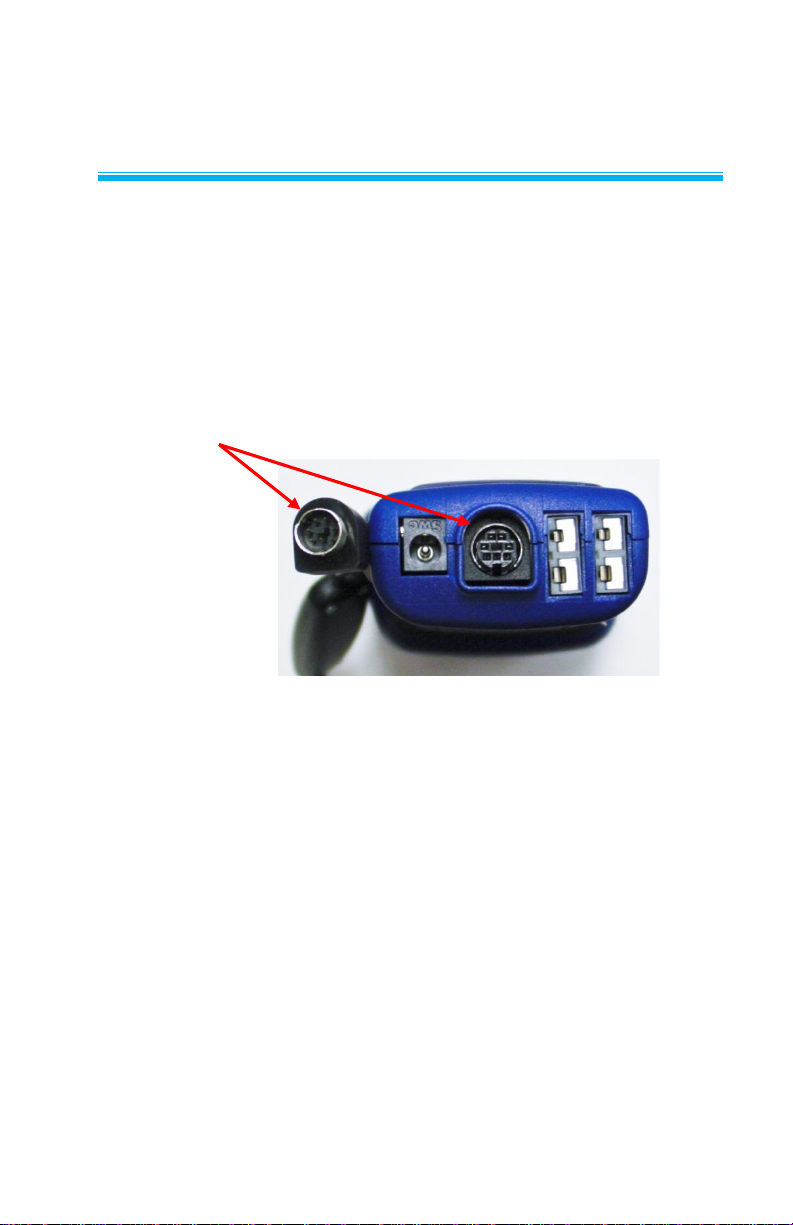
“D” Shaped
mini-DIN connector
Chapter 2
Setting-up
Connecting the VOC Probe to Instrument
The VOC probes have a “D” shape overmolding on the mini-DIN
connector which must align with the connector at the base of the
multi-functional instrument models 9565-X, 9565-P, TA465-X,
TA465-P and 7575-X. This will ensure the probe is properly
connected and remains so during use.
Using the Probe
The sensing probe relies on the diffusion of air. For best results, try to
keep the sensing probe surrounded by moving air. Do not breathe on
the probe.
Humans exhale CO2 levels exceeding 10,000 ppm and it may take
time for the probes that measure CO2 to re-stabilize, and high
humidity from your breath can cause condensation on the UV light
source in the PID sensor.
3
Page 12
Configuring the Probe and Instrument
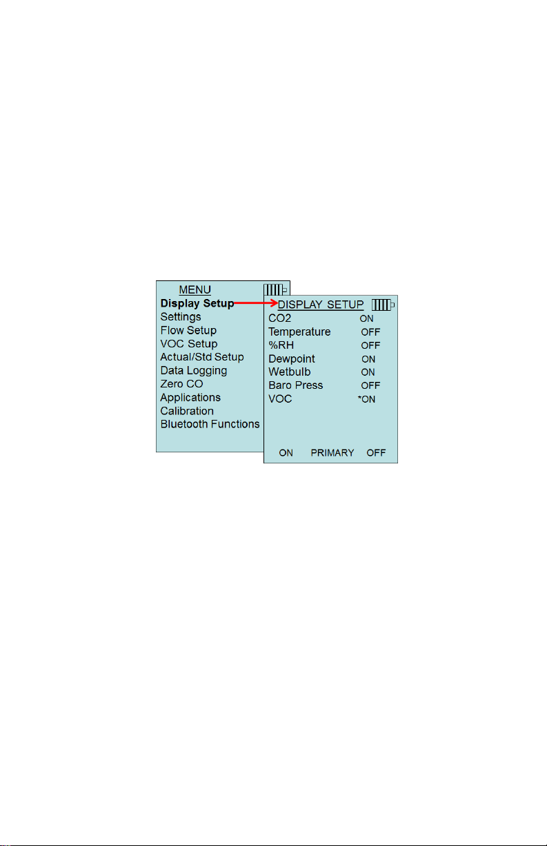
DISPLAY SETUP
Display Setup menu is where you will setup the desired parameters to
be displayed on the instrument screen. With a parameter highlighted
you can then use the ON soft key to have it show up on the instrument
screen or select the OFF soft key to turn off the parameter. Use
PRIMARY soft key to have a parameter show up on the instrument
screen in a larger display. A total of 5 parameters can be shown on
the display, 1 primary (large font) and 4 secondary. Parameters
shown in the Display Setup screen are dependent on the type of
probe currently connected.
4 Chapter 2
Page 13
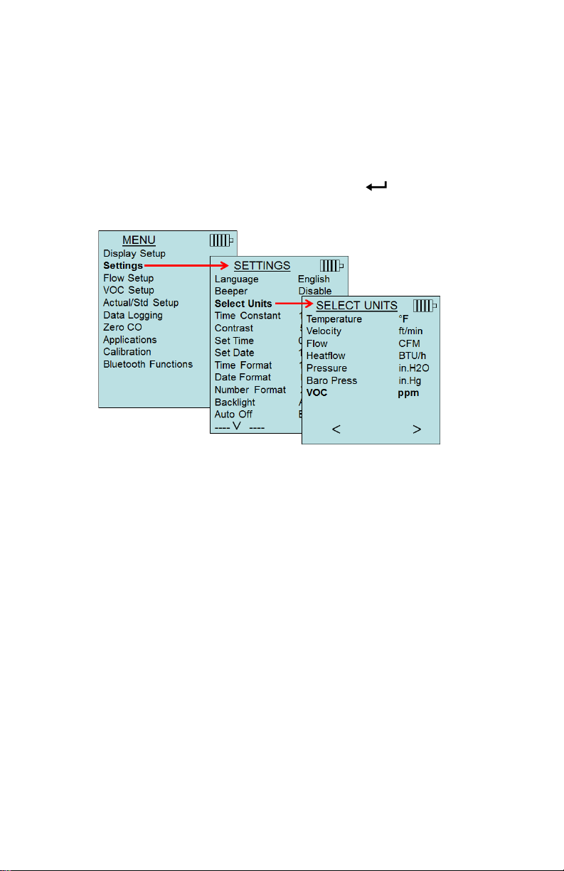
SETTINGS
Settings menu is where you can set the general settings. These
include Language, Beeper, Select Units, Time Constant, Contrast,
Set Time, Set Date, Time Format, Date Format, Number Format,
Backlight, and Auto Off.
Use the or keys to select an option, and the or soft keys to
change the settings for each option. Press the key to accept
settings.
Setting-up 5
Page 14
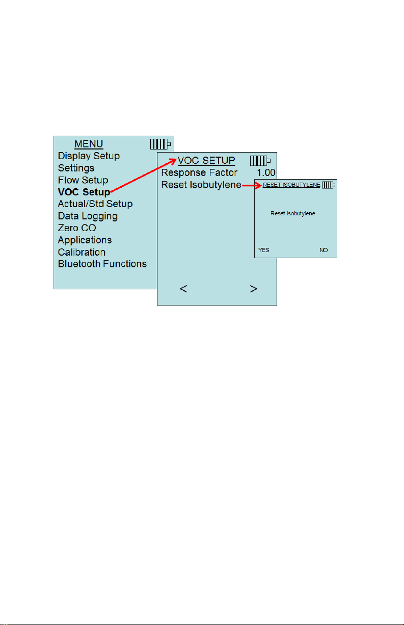
VOC SETUP
The Response Factor of a specific gas can be inputted by the user.
The response Factor is used to calculate the actual concentration
of a specific VOC.
Reset Isobutylene will restore the factory to factory conditions for
Isobutylene (56.11).
6 Chapter 2
Page 15

DATA LOGGING
Measurements
Measurements to be logged to memory are independent of
measurements on the display, and must therefore be selected under
DATA LOGGING Measurements.
When set to ON, measurement will be logged to memory.
When set to DISPLAY, measurement will be logged to memory if
it is visible on the main running screen.
When set to OFF, measurement will not be logged to memory
Refer to the instrument manual (Chapter 3: Data Logging →
“LogMode/Log Settings”) for information on the different logging
formats available.
Setting-up 7
Page 16

(This page intentionally left blank)
8 Chapter 2
Page 17

Gas/ VOC
The most common name for the VOC.
CAS No.
Find the VOC using the CAS No.
Formula
To assist in identifying the VOC and to determine
the VOC’s molecular weight.
Response
Factor (RF)
Multiply the displayed concentration by the
Response Factor to calculate the actual
concentration of the VOC.
NOTE: The Response Factor (RF) can be
programmed into the instrument via the VOC
SETUP menu.
Chapter 3
Response Factors
TSI Volatile Organic Compound (VOC) probes are calibrated using
isobutylene, but the sensor’s Photo Ionization Detector (PID) is a
broadband VOC detector with a sensitivity that differs for each VOC
compound.
PID lamps can be created with a number of gasses, each of which
has different photon energy. TSI’s PID probes use Krypton gas, with
photon energy of 10.6 eV (Electron Volt) that offers a long lamp life
and responds to a wide range of gases.
If you know what VOC you are measuring, the table in this section will
allow you to calculate the real concentration for your specific VOC
that responds to a 10.6 eV lamp source.
NOTE: These are approximate values, so for best accuracy, you
should calibrate with the relevant VOC.
NOTE: TSI PID sensors cannot measure all VOCs or gases. VOCs
that have an electron-volt potential greater than or equal (≥) to
10.6 eV will give no response since they cannot be ionized by the
10.6 eV lamp source. Semi-Volatile Organic Compounds (SVOC)
cannot be measured if the vapor pressure is too low (a few ppm at
20°C) to volatize the compound.
The table includes four columns:
9
Page 18

10 Chapter 3
Gas/VOC
CAS No.
Formula
Response Factor
Acetaldehyde
75-07-0
C2H4O
4.9
Acetic Acid
64-17-7
C2H4O2
36.2
Acetic Anhydride
108-24-7
C4H6O3
4.0
Acetone
67-64-1
C3H6O
0.7
Acrolein
107-02-8
C3H4O
4.0
Acrylic Acid
79-10-7
C3H4O2
2.7
Allyl alcohol
107-18-6
C3H6O
2.1
Allyl chloride
107-05-1
C3H5Cl
4.5
Ammonia
7664-41-7
H3N
8.5
Amyl acetate, n-
628-63-7
C7H14O2
1.8
Amyl alcohol
71-41-0
C5H12O
3.2
Aniline
62-53-3
C6H7N
0.5
Anisole
100-66-3
C7H8O
0.5
Arsine
7784-42-1
AsH3
2.5
Asphalt, petroleum fumes
8052-42-4
C6H6
1.0
Benzaldehyde
100-52-7
C7H6O
0.9
Benzene
71-43-2
C6H6
0.5
Benzenethiol
108-98-5
C6H5SH
0.7
Benzonitrile
100-47-0
C7H5N
0.7
Benzyl alcohol
100-51-6
C7H8O
1.3
Benzyl chloride
100-44-7
C7H7Cl
0.6
Benzyl formate
104-57-4
C8H8O2
0.8
Biphenyl
92-52-4
C12H10
0.4
Bis(2,3-epoxypropyl) ether
2238-07-5
C6H10O3
3.0
Bromine
7726-95-6
Br2
20.0
Bromobenzene
108-86-1
C6H5Br
0.7
Bromoethane
74-96-4
C2H5Br
5.0
Bromoethyl methyl ether, 2-
6482-24-2
C3H7OBr
2.5
Bromoform
75-25-2
CHBr3
2.8
Bromopropane, 1-
106-94-5
C3H7Br
1.3
Butadiene
106-99-0
C4H6
0.8
Butadiene diepoxide,1,3-
1464-53-5
C4H6O2
4.0
Butane, n-
106-97-8
C4H10
46.3
Butanol, 1-
71-36-3
C4H10O
4.0
Buten-3-ol, 1-
598-32-3
C4H8O
1.2
Butene, 1-
106-98-9
C4H8
1.3
Butoxyethanol, 2-
111-76-2
C6H14O2
1.1
Butyl acetate, n-
123-86-4
C6H12O2
2.4
Butyl acrylate, n-
141-32-2
C7H12O2
1.5
Butyl lactate
138-22-7
C7H14O3
2.5
Butyl mercaptan
109-79-5
C4H10S
0.5
Butylamine, 2-
513-49-5
C4H11N
0.9
Butylamine, n-
109-73-9
C4H11N
1.0
Camphene
565-00-4
C10H16
0.5
Carbon disulfide
75-15-0
CS2
1.4
Carbon tetrabromide
558-13-4
CBr4
3.0
Page 19

Response Factors 11
Gas/VOC
CAS No.
Formula
Response Factor
Carvone, R-
6485-40-1
C10H14O
1.0
Chlorine dioxide
10049-04-4
ClO2
1.0
Chloro-1,3-butadiene, 2-
126-99-8
C4H5Cl
3.2
Chlorobenzene
108-90-7
C6H5Cl
0.5
Chloroethanol, 2-
107-07-3
C2H5ClO
10.0
Chloroethyl methyl ether, 2-
627-42-9
C3H7ClO
2.6
Chlorotoluene, o-
95-49-8
C7H7Cl
0.5
Chlorotoluene, p-
108-41-8
C7H7Cl
0.5
Chlorotrifluoroethylene
79-38-9
C2ClF3
1.0
Citral
5392-40-5
C10H16O
1.0
Citronellol
26489-01-0
C10H20O
1.0
Cresol, m-
108-39-4
C7H8O
1.1
Cresol, o-
95-48-7
C7H8O
1.1
Cresol, p-
106-44-5
C7H8O
1.1
Crotonaldehyde
4170-30-3
C4H6O
1.0
Cumene
98-82-8
C9H12
0.6
Cyclohexane
110-82-7
C6H12
1.3
Cyclohexanol
108-93-0
C6H12O
2.9
Cyclohexanone
108-94-1
C6H10O
1.1
Cyclohexene
110-83-8
C6H10
0.8
Cyclohexylamine
108-91-8
C6H13N
1.0
Cyclopentane
287-92-3
C5H10
4.0
Decane, n-
124-18-5
C10H22
1.0
Diacetone alcohol
123-42-2
C6H12O2
0.8
Dibenzoyl peroxide
94-36-0
C14H10O4
0.8
Dibromochloromethane
124-48-1
CHBr2Cl
10.0
Dibromoethane 1,2-
106-93-4
C2H4Br2
2.0
Dibutyl hydrogen phosphate
107-66-4
HC8H18PO4
4.0
Dichloro-1-propene, 2,3-
78-88-6
C3H4Cl2
1.4
Dichloroacetylene
7572-29-4
C2Cl2
5.0
Dichlorobenzene o-
95-50-1
C6H4Cl2
0.5
Dichloroethene, 1,1-
75-35-4
C2H2Cl2
1.0
Dichloroethene, cis-1,2-
156-59-2
C2H2Cl2
0.8
Dichloroethene, trans-1,2-
540-59-0
C2H2Cl2
0.7
Dichloroethylene 1,2-
540-59-0
C2H2Cl2
0.8
Dichloromethane
75-09-2
CH2Cl2
39.0
Dicyclopentadiene
77-73-6
C10H12
0.9
Diesel Fuel
68334-30-5 0.8
Diethyl ether
60-29-7
C4H10O
0.9
Diethyl maleate
141-05-9
C8H12O4
2.0
Diethyl phthalate
84-66-2
C12H14O4
1.0
Diethyl sulphate
64-67-5
C4H10SO4
3.0
Diethyl sulphide
352-93-2
C4H10S
0.6
Diethylamine
109-89-7
C4H11N
1.0
Diethylaminoethanol, 2-
100-37-8
C6H15ON
2.7
Diethylaminopropylamine, 3-
104-78-9
C7H18N2
1.0
Page 20

Gas/VOC
CAS No.
Formula
Response Factor
Dihydrogen selenide
7783-07-5
H2Se
1.0
Dihydroxybenzene, 1,2
120-80-9
C6H6O2
1.0
Dihydroxybenzene, 1,3
108-46-3
C6H6O2
1.0
Diisobutylene
107-39-1
C8H16
0.6
Diisopropyl ether
108-20-3
C6H14O
0.7
Diisopropylamine
108-18-9
C6H15N
0.7
Diketene
674-82-8
C4H4O2
2.2
Dimethoxymethane
109-87-5
C3H8O2
1.4
Dimethyl cyclohexane, 1,2-
583-57-3
C8H16
1.1
Dimethyl disulphide
624-92-0
C2H6S2
0.2
Dimethyl ether
115-10-6
C2H6O
1.3
Dimethyl phthalate
131-11-3
C10H10O4
1.0
Dimethyl sulphide
75-18-3
C2H6S
0.5
Dimethylacetamide N,N-
127-19-5
C4H9NO
1.3
Dimethylamine
124-40-3
C2H7N
1.4
Dimethylaminoethanol
108-01-0
C4H11NO
1.5
Dimethylaniline, NN-
121-69-7
C8H11N
0.6
Dimethylbutyl acetate
108-84-9
C8H16O2
1.6
Dimethylethylamine, NN-
598-56-1
C4H11N
0.8
Dimethylformamide
68-12-2
C3H7NO
0.9
Dimethylheptan-4-one, 2,6-
108-83-8
C9H18O
0.8
Dimethylhydrazine, 1,1-
57-14-7
C2H8N2
1.0
Dinitrobenzene, m-
99-65-0
C6H4N2O4
3.0
Dinitrobenzene, p-
100-25-4
C6H4N2O4
5.0
Dinonyl phthalate
84-76-4
C26H42O4
1.0
Dioxane 1,2-
C4H8O2
1.5
Dioxane 1,4-
123-91-1
C4H8O2
1.5
Dipentene
138-86-3
C10H16
0.9
Diphenyl ether
101-84-8
C12H10O
0.8
Disulphur dichloride
10025-67-9
S2Cl2
3.0
Di-tert-butyl-p-cresol
2409-55-4
C11H16O
1.0
Divinylbenzene
1321-74-0
C10H10
0.4
Dodecanol
112-53-8
C12H26O
0.9
Epichlorohydrin
106-89-8
C3H5ClO
8.0
Epoxypropyl isopropyl ether,
2,3-
4016-14-2
C6H12O2
1.1
Ethanol
64-17-5
C2H6O
8.7
Ethanolamine
141-43-5
C2H7NO
3.0
Ethoxy-2-propanol, 1-
1569-02-4
C5H10O2
2.0
Ethoxyethanol, 2-
110-80-5
C4H10O2
29.8
Ethoxyethyl acetate, 2-
111-15-9
C6H12O3
3.0
Ethyl(S)-(-)-lactate
97-64-3
C5H10O3
3.0
Ethyl acetate
141-78-6
C4H8O2
3.6
Ethyl acrylate
140-88-5
C5H8O2
2.0
Ethyl amine
75-04-7
C2H7N
1.0
Ethyl benzene
100-41-4
C8H10
0.5
12 Chapter 3
Page 21

Gas/VOC
CAS No.
Formula
Response Factor
Ethyl butyrate
105-54-4
C6H12O2
1.0
Ethyl chloroformate
541-41-3
C3H5O2Cl
80.0
Ethyl cyanoacrylate
7085-85-0
C6H7O2N
1.5
Ethyl decanoate
110-38-3
C12H24O2
1.8
Ethyl formate
109-94-4
C3H6O2
30.0
Ethyl hexanoate
123-66-0
C8H16O2
2.6
Ethyl hexanol, 2-
105-76-7
C8H18O
1.5
Ethyl hexyl acrylate, 2-
103-11-7
C11H20O2
1.0
Ethyl mercaptan
75-08-1
C2H6S
0.7
Ethyl octanoate
106-32-1
C10H20O2
2.3
Ethylene
74-85-1
C2H4
8.0
Ethylene glycol
107-21-1
C2H6O2
20.0
Ethylene oxide
75-21-8
C2H4O
15.0
Ferrocene
102-54-5
C10H10Fe
0.8
Formamide
75-12-7
CH3ON
2.0
Furfural
98-01-1
C5H4O2
1.4
Furfuryl alcohol
98-00-0
C5H6O2
2.0
Gasoline vapors
8006-61-9 1.1
Gasoline vapors92 octane
8006-61-9 0.8
Germane
7782-65-2
GeH4
10.0
Glutaraldehyde
111-30-8
C5H8O2
0.9
Heptan-2-one
110-43-0
C7H14O
0.7
Heptan-3-one
106-35-4
C7H14O
0.8
Heptane n-
142-82-5
C7H16
2.1
Hexamethyldisilazane,
1,1,1,3,3,3-
999-97-3
C6H19NSi2
1.0
Hexamethyldisiloxane
107-46-0
C6H18OSi2
0.3
Hexan-2-one
591-78-6
C6H12O
0.8
Hexane n-
110-54-3
C6H14
4.2
Hexene, 1-
592-41-6
C6H12
0.9
Hydrazine
302-01-2
H4N2
3.0
Hydrogen peroxide
7722-84-1
H2O2
4.0
Hydrogen sulfide
7783-06-4
H2S
4.0
Hydroquinone
123-31-9
C6H6O2
0.8
Hydroxypropyl acrylate 2-
999-61-1
C6H10O3
1.5
Iminodi(ethylamine) 2,2-
111-40-0
C4H13N3
0.9
Iminodiethanol 2,2'-
111-42-2
C4H11NO2
1.6
Indene
95-13-6
C9H8
0.5
Iodine
7553-56-2
I2
0.2
Iodoform
75-47-8
CHI3
1.5
Iodomethane
74-88-4
CH3I
0.4
Isoamyl acetate
123-92-2
C7H14O2
1.6
Isobutane
75-28-5
C4H10
8.0
Isobutanol
78-83-1
C4H10O
3.5
Isobutyl acetate
110-19-0
C6H12O2
2.3
Isobutyl acrylate
106-63-8
C7H12O2
1.3
Response Factors 13
Page 22

Gas/VOC
CAS No.
Formula
Response Factor
Isobutylene
115-11-7
C4H8
1.0
Isobutyraldehyde
78-84-2
C4H8O
1.2
Isodecanol
25339-17-7
C10H22O
0.9
Isononanol
2452-97-9
C9H20O
1.5
Isooctane
565-75-3
C8H18
1.1
Isooctanol
26952-21-6
C8H18O
1.7
Isopentane
78-78-4
C5H12
6.0
Isophorone
78-59-1
C9H14O
0.8
Isoprene
78-79-5
C5H8
0.7
Isopropanol
67-63-0
C3H8O
4.4
Isopropyl acetate
108-21-4
C5H10O2
2.2
Isopropyl chloroformate
108-23-6
C4H7O2Cl
1.6
Jet Fuel JP-4
0.8
Jet Fuel JP-5
0.7
Jet Fuel JP-8
0.7
Ketene
463-51-4
C2H2O
3.0
Maleic anhydride
108-31-6
C4H2O3
2.0
Mercaptoacetic acid
68-11-1
C2H4O2S
1.0
Mesitylene
108-67-8
C9H12
0.3
Methacrylic acid
79-41-4
C4H6O2
2.3
Methacrylonitrile
126-98-7
C4H5N
5.0
Methanol
67-56-1
CH4O
200.0
Methoxyethanol, 2-
109-86-4
C3H8O2
2.7
Methoxyethoxyethanol, 2-
111-77-3
C5H12O3
1.4
Methoxymethylethoxy-2propanol
34590-94-8
C7H16O3
1.3
Methoxypropan-2-ol
107-98-2
C4H10O2
3.0
Methoxypropyl acetate
108-65-6
C6H12O3
1.2
Methyl acetate
79-20-9
C3H6O2
5.2
Methyl acrylate
96-33-3
C4H6O2
3.4
Methyl bromide
74-83-9
CH3Br
1.9
Methyl cyanoacrylate
137-05-3
C5H5O2N
5.0
Methyl ethyl ketone
78-93-3
C4H8O
0.8
Methyl ethyl ketone
peroxides
1338-23-4
C8H18O2
0.8
Methyl isobutyl ketone
108-10-1
C6H12O
0.8
Methyl isothiocyanate
556-61-6
C2H3NS
0.6
Methyl mercaptan
74-93-1
CH4S
0.7
Methyl methacrylate
80-62-6
C5H8O2
1.6
Methyl propyl ketone
107-87-9
C5H10O
0.8
Methyl salicylate
119-36-8
C8H8O3
1.2
Methyl sulphide
75-18-3
C2H6S
0.5
Methyl t-butyl ether
1634-04-4
C5H12O
0.8
Methyl-2-propen-1-ol, 2-
51-42-8
C4H8O
1.1
Methyl-2-pyrrolidinone, N-
872-50-4
C5H9NO
0.9
Methyl-4,6-dinitrophenol, 2-
534-52-1
C7H6N2O5
3.0
14 Chapter 3
Page 23

Gas/VOC
CAS No.
Formula
Response Factor
Methyl-5-hepten-2-one, 6-
110-93-0
C8H14O
0.8
Methylamine
74-89-5
CH5N
1.4
Methylbutan-1-ol, 3-
123-51-3
C5H12O
3.4
Methylcyclohexane
108-87-2
C7H14
1.1
Methylcyclohexanol, 4-
589-91-3
C7H14O
2.4
Methylcyclohexanone 2-
583-60-8
C7H12O
1.0
Methylheptan-3-one, 5-
541-85-5
C8H16O
0.8
Methylhexan-2-one, 5-
110-12-3
C7H14O
0.8
Methylhydrazine
60-34-4
CH6N2
1.3
Methyl-N-2,4,6tetranitroaniline, N-
479-45-8
C7H5N5O8
3.0
Methylpent-3-en-2-one, 4-
141-79-7
C6H10O
0.7
Methylpentan-2-ol, 4-
108-11-2
C6H14O
2.8
Methylpentane-2,4-diol, 2-
107-41-5
C6H14O2
4.0
Methylpropan-2-ol, 2-
75-65-0
C4H10O
3.5
Methylstyrene
25013-15-4
C9H10
0.5
Mineral oil
8042-47-5 0.8
Mineral spirits
64475-85-0 0.8
Naphthalene
91-20-3
C10H8
0.4
Nitric oxide
10102-43-9
NO
8.0
Nitroaniline 4-
100-01-6
C6H6N2O2
0.8
Nitrobenzene
98-95-3
C6H5NO2
1.7
Nitrogen dioxide
10102-44-0
NO2
10.0
Nitrogen trichloride
10025-85-1
NCl3
1.0
Nonane, n-
111-84-2
C9H20
1.3
Norbornadiene, 2,5-
121-46-0
C7H8
0.6
Octachloronaphthalene
2234-13-1
C10Cl8
1.0
Octane, n-
111-65-9
C8H18
1.6
Octene, 1-
111-66-0
C8H16
0.7
Oxydiethanol 2,2-
111-46-6
C4H10O3
4.0
Paraffin wax, fume
8002-74-2 1.0
Paraffins, normal
64771-72-8 1.0
Pentacarbonyl iron
13463-40-6
FeC5O5
1.0
Pentan-2-one
107-87-9
C5H10O
0.8
Pentan-3-one
96-22-0
C5H10O
0.8
Pentandione, 2,4-
123-54-6
C5H8O2
0.8
Pentane, n-
109-66-0
C5H12
7.9
Peracetic acid
79-21-0
C2H4O3
2.0
Petroleum ether
64742-82-1
C6H14
0.9
Phenol
108-95-2
C6H6O
1.2
Phenyl propene, 2-
98-83-9
C9H10
0.4
Phenyl-2,3-epoxypropyl
ether
122-60-1
C9H10O2
0.8
Phenylenediamine, p-
106-50-3
C6H8N2
0.6
Phosphine
7803-51-2
PH3
2.0
Picoline, 3-
108-99-6
C6H7N
0.9
Response Factors 15
Page 24

Gas/VOC
CAS No.
Formula
Response Factor
Pinene, alpha
80-56-8
C10H16
0.3
Pinene, beta
127-91-3
C10H16
0.3
Piperidine
110-89-4
C5H11N
0.9
Piperylene
504-60-9
C5H8
0.7
Prop-2-yn-1-ol
107-19-7
C3H4O
1.3
Propan-1-ol
71-23-8
C3H8O
4.8
Propane-1,2-diol, total
57-55-6
C3H8O2
10.0
Propene
115-07-1
C3H6
1.4
Propionaldehyde
123-38-6
C3H6O
1.7
Propionic acid
79-09-4
C3H6O2
8.0
Propyl acetate, n-
109-60-4
C5H10O2
2.5
Propylene oxide
75-56-9
C3H6O
7.0
Propyleneimine
75-55-8
C3H7N
1.3
Pyridine
110-86-1
C5H5N
0.8
Pyridylamine 2-
504-29-0
C5H6N2
0.8
Styrene
100-42-5
C8H8
0.4
Terphenyls
C18H14
0.6
Terpinolene
586-62-9
C10H16
0.5
Tert-butanol
75-65-0
C4H10O
2.6
Tetrabromoethane, 1,1,2,2-
79-27-6
C2H2Br4
2.0
Tetracarbonylnickel
13463-39-3
NiC4O4
1.0
Tetrachloroethylene
127-18-4
C2Cl4
0.7
Tetrachloronaphthalenes,all
isomers
20020-02-4
C10H4Cl4
1.0
Tetraethyl orthosilicate
78-10-4
C8H20O4Si
2.0
Tetrafluoroethylene
116-14-3
C2F4
1.0
Tetrahydrofuran
109-99-9
C4H8O
1.6
Tetramethyl succinonitrile
3333-52-6
C8H12N2
1.0
Therminol
1.0
Toluene
108-88-3
C7H8
0.5
Toluene-2,4-diisocyanate
584-84-9
C9H6N2O2
1.6
Toluenesulphonylchloride, p-
98-59-9
C7H7SO2C
l
3.0
Toluidine, o-
95-53-4
C7H9N
0.5
Tributyl phosphate
126-73-8
C12H27O4
P
5.0
Tributylamine
102-82-9
C12H27N
1.0
Trichlorobenzene 1,2,4-
120-82-1
C6H3Cl3
0.6
Trichloroethylene
79-01-6
C2HCl3
0.7
Trichlorophenoxyacetic acid,
2,4,5-
93-76-5
C8H5O3Cl3
1.0
Triethylamine
121-44-8
C6H15N
0.9
Trimethylamine
53-50-3
C3H9N
0.5
Trimethylbenzene, 1,3,5-
108-67-8
C9H12
0.3
Turpentine
8006-64-2
C10H16
0.6
TVOC
1.0
16 Chapter 3
Page 25

Gas/VOC
CAS No.
Formula
Response Factor
Undecane, n-
1120-21-4
C11H24
0.9
Vinyl acetate
108-05-2
C4H6O2
1.1
Vinyl bromide
593-60-2
C2H3Br
1.0
Vinyl chloride
75-01-4
C2H3Cl
2.1
Vinyl-2-pyrrolidinone, 1-
88-12-0
C6H9NO
0.9
Xylene mixed isomers
1330-20-7
C8H10
0.4
Xylene, m-
108-38-3
C8H10
0.4
Xylene, o-
95-47-6
C8H10
0.6
Xylene, p-
106-42-3
C8H10
0.6
Xylidine, all
1300-73-8
C8H11N
0.7
Response Factors 17
Page 26

(This page intentionally left blank)
18 Chapter 3
Page 27

Chapter 4
Field Testing and Calibration
Overview
Due to the nature of the PID sensor and the presence of VOCs in air
along with other environmental factors such as altitude, temperature
and relative humidity, the zero value of the VOC probe will shift over
time. TSI recommends testing the probe performance each time
the instrument is used to make measurements. This is a common
practice within the gas measurement community which includes IAQ
consultants and industrial hygienists.
Probe Verification
Verifying the probe performance
can easily be accomplished in
the field by comparing it to
certified zero and span
calibration gases. To do this,
attach the probe with the
calibration collar to a bottle of
Zero Gas and compare to the
instrument readings (also
referred to as a “Bump Test”). If
the probe reads any number
other than 0, the PID sensor has
drifted and needs to be
re-calibrated.
NOTE: With probe attached, power on the instrument for 10 minutes
before verifying performance. This allows the instrument and probe
electronics to stabilize to produce best results.
19
Page 28

TSI Recommended Accessories for Testing or Calibrating PID Probes
Zero Gas—80% Nitrogen/20% Oxygen
Span Gas—1 ppm Isobutylene in balance Nitrogen—use with
ppb probe
Span Gas—10 ppm Isobutylene in balance Nitrogen—use with
ppb probe
Span Gas—20 ppm Isobutylene in balance Nitrogen—use with
ppm probe
Span Gas—100 ppm Isobutylene in balance Nitrogen—use with
ppm probe
0.3 to 0.5 L/min flow rate Continuous Flow Regulator
Tygon® tubing 0.250 in. (6.35 mm) OD, 0.125 in. (3.175 mm) ID
VOC probe calibration collar (included with probe)
When spanning with an isobutylene gas, select a concentration value
that is closest to the desired measurement range. This will result in
maximum accuracy of the PID sensors readings.
Example 1 (ppb)
If you have a ppb PID probe and want to measure VOCs in the low
ppb range, span calibrating with a 1 ppm isobutylene gas will give
more accurate results than span calibrating with a 10 ppm
isobutylene gas. If you would like to measure VOCs in the mid to
upper range of the PID sensor, calibrating with 10 ppm isobutylene
span gas would be appropriate.
Example 2 (ppm)
If you have a ppm PID probe and want to measure VOCs in the low
ppm range, span calibration with a 20 ppm isobutylene gas will give
more accurate results, than span calibrating with 100 ppm
isobutylene gas will. If you would like to measure VOCs in the mid to
upper range of the PID sensor, calibrating with 100 ppm isobutylene
span gas would be appropriate.
Zero, Span gasses and regulators that meet TSI’s requirements are
available internationally from PortaGas at www.portagas.com in 103
liter bottle configurations.
20 Chapter 4
Page 29

PID Probe Calibration
NOTES
With probe attached power on the instrument for 10 minutes
before calibrating the probe. This allows the instrument and
probe electronics to stabilize to produce best results.
Field calibration is required if a new replacement PID sensor is
installed on the probe.
Restore to Factory Calibration before performing field
calibration.
After restoring Factory Calibration, try the “Bump Test” again at
0 ppm and/or at a known concentration of Isobutylene in balance
Nitrogen gas. If readings are still out of tolerance, then proceed
with field calibration procedure.
MENU
Zero Press
Display Setup
Settings
Flow Setup
VOC Setup
Actual/Std Setup
Data Logging
Zero CO
Applications
Calibration
Bluetooth Functions
CALIBRATION
Calibrate Temp
Calibrate Vel
Calibrate %RH
Calibrate B.P.
Calibrate CO2
Calibrate CO
Calibrate VOC
Restore Factory Cal
If the probe reads any number other than 0 when tested against a
zero gas, the PID sensor has drifted and needs to be re-calibrated
using the following instructions. These instructions are also applicable
if the PID sensor has been replaced in the field.
Accessing the Calibration Menu
To access the CALIBRATION menu, press the MENU key and scroll
down to CALIBRATION and press ENTER. Highlight Calibrate VOC
and then press ENTER.
Field Testing and Calibration 21
Page 30

NOTE
The measurement capabilities of the instrument and probe will
determine what appears in the main MENU and CALIBRATION
menu. Instrument models using detachable probes must have the
probe attached to perform field calibrations. This screen display
above is from the 9565-P VelociCalc® Multi-Function Ventilation
Meter with VOC probe attached.
Calibrate VOC
Step 3—Zero Calibration.
After pressing ENTER with the zero
calibration gas connected, the instrument
begins to take data. A bar graph will
appear showing the time remaining. The
time allocated by the instruments
firmware for zero is sufficient for zeroing.
CALIBRATE VOC
Connect zero gas
then press
ENTER
CALIBRATE VOC
0.00 ppm
A probe calibration collar (included with probe), zero calibration gas,
span calibration gas, gas regulator and tubing are required to perform
the calibration. The gas regulator used to control the flow should be
capable of providing 0.3 L/min. Follow the on-screen instructions to
complete the calibration.
Step 1—Grasp probe handle and pull PID sensor protective cap off.
Step 2—Slide calibration collar onto probe and attach to gas cylinder
using tubing.
22 Chapter 4
Page 31

Step 4—Span Calibration.
For best results, run the span gas with
the probe attached for 60 seconds before
pressing the ENTER button to conduct
the span calibration.
After pressing ENTER with the span
calibration gas connected, the instrument
begins to take data. A bar graph will
appear showing the time remaining.
CALIBRATE VOC
Connect span gas
then press
ENTER
CALIBRATE VOC
9.41 ppm
Step 5—Span Adjustment
Once the countdown is complete, the
VOC concentration as measured by the
probe is displayed along with the percent
of adjustment.
In this example, the span gas is rated at
10 ppm. Use the UP or DOWN arrow
keys to adjust offset to match the span
gas concentration. Press ENTER to
accept and to return to the
CALIBRATION menu.
CALIBRATE VOC
9.41 ppm
0.0 % Adjustment
CALIBRATE VOC
10.00 ppm
6.3 % Adjustment
Calibrate CO2
This calibration option applies to meters and probes capable of
measuring CO2. A probe calibration collar, zero calibration gas, span
calibration gas, gas regulator and tubing are required to perform the
calibration. The gas regulator used to control the flow should be
capable of providing 0.3 L/min. Follow the on-screen instructions to
complete the calibration.
Requirements
Probe calibration collar (included
with IAQ and VOC probes)
Span calibration gas, 5000 ppm
maximum
Zero Gas – 80% Nitrogen /
20% Oxygen
0.3 L/min flow rate Continuous
Flow Regulator
Tygon tubing 0.250 in. (6.35 mm) OD, 0.125 in. (3.175 mm) ID
Field Testing and Calibration 23
Page 32

NOTE
If probe measures VOC gasses, remove VOC sensor first.
Step 2— Bump Test
Measure concentration with 0 ppm calibration gas flowing through the
calibration collar. Do the same with the Span Gas. If readings are out
of tolerance, Restore CO2 Factory Calibration (see RESTORE
FACTORY CAL) and then perform the Bump Test again at 0 ppm and
Span. If readings are still OOT, proceed with Field Calibration.
Step 3—Zero Calibration.
After pressing ENTER with the zero
calibration gas connected, the instrument
will begin to take data. A bar graph will
appear showing the time remaining.
Step 4—Span Calibration.
After pressing ENTER with the span
calibration gas connected, the instrument
will begin to take data. A bar graph will
appear showing the time remaining.
Pull PID sensor protective cap off
Remove PID sensor
Unscrew collar
Gently remove small PCB
Step 1—Slide calibration collar onto probe and attach to gas cylinder
using tubing.
24 Chapter 4
Page 33

Step 5—Span Adjustment.
Once the countdown is complete, the
CO2 concentration as measured by the
probe is displayed along with the percent
of adjustment.
In this example, the span gas is rated at
1000 ppm. Use the UP or DOWN arrow
keys to adjust offset to match the span
gas concentration. Press ENTER to
accept and to return to the
CALIBRATION menu.
Calibrate Temp
This calibration option applies to all meters and probes capable of
measuring temperature. The temperature calibration can be adjusted
±6.0°F (±3.3°C). Compare the instruments temperature reading to a
reference standard and make changes as required.
Step 1—Use the UP or DOWN arrow keys to adjust offset.
Step 2—Press ENTER to accept and to return to CALIBRATION
menu.
In this example, the temperature measured by the probe is 75.3°F
and the reference temperature is 73.6°F. Adjusting the offset by
-1.7°F allows the probe to match the reference standard.
Field Testing and Calibration 25
Page 34

Calibrate %RH
RESTORE FACTORY CAL
Restore Temp
Restore Vel
Restore %RH
Restore Press
Restore B.P.
Restore CO2
Restore CO
Restore VOC
RESTORE VOC
Are you Sure?
YES NO
This calibration option applies to meters and probes capable of
measuring relative humidity. Compare the instruments relative
humidity reading to a reference standard and make changes as
required. The Offset can be adjusted ±12.0% RH.
Step 1—Use the UP or DOWN arrow keys to adjust offset.
Step 2—Press ENTER to accept and to return to CALIBRATION
menu.
In this example, the relative humidity measured by the probe is
30.5 %RH and the reference humidity is 31.6 %RH. Adjusting the
offset by 1.1% allows the probe match the reference standard.
RESTORE FACTORY CAL
This option resets the field calibration for any measurement
parameter back to the last factory calibration. To restore the last
factory calibration for any measurement parameter, the probe must
be attached to the meter on models with detachable probe.
26 Chapter 4
Page 35

Condition
Recommended Action
Sensitivity has dropped too much (note the
change required when checking calibration)
Clean lamp
The baseline is climbing after you zero the PID
Replace electrode stack
The PID becomes sensitive to humidity
Replace electrode stack
The baseline is unstable or shifts when the PID
is moved
Replace electrode stack
Chapter 5
Probe Maintenance
The electronics in the PID sensor in the VOC probes are not
accessible. However, periodic sensor maintenance of the electrode
stack and lamp may be needed for optimal performance.
The PID lamp will need cleaning from time to time. How often
depends on the environment you are measuring in. If you are
measuring indoor air quality where the VOC concentrations are low
and there are few particulates, then a monthly or even less frequent
cleaning may be adequate. However, if you are measuring high VOC
concentrations and particulates are present in high concentrations,
check calibration frequently and clean the lamp. When the PID has
lost sensitivity, change the stack as explained below in the sections
entitled “Removing Electrode Stack and Lamp” and “Refitting
Electrode Stack and Lamp”.
The PID needs maintenance if:
Removing the Electrode Stack and Lamp
CAUTION: Always use the Electrode Stack Removal Tool (included
with replacement stack); any other tools may damage your PID and
void the warranty.
1. Remove cap and PID sensor from VOC probe, as shown in
Figure 1.
2. Gently pull the sensor from the probe.
3. Place the PID, top side down, onto a clean surface.
4. Insert electrode stack removal tool into the two slots on the sides
of the PID (as shown in Figure 2) and squeeze together until
electrode stack and lamp are released.
27
Page 36

CAUTION: Electrode stack and lamp may jump off sensor and
become lost if removed when the PID is right-side up.
5. Carefully lift the PID body away from the electrode stack and
lamp.
Figure 1. Removing Cap and PID Sensor from VOC Probe
NOTES:
If the lamp lodges in the sensor, use tweezers to carefully
remove it.
If the spring behind the lamp also comes out, replace it in the
sensor housing.
Figure 2. Using Electrode Stack Removal Tool
28 Chapter 5
Page 37

Cleaning the PID Lamp
Cleaning the PID lamp is recommended as a first step for PIDs
needing service. Use the procedure described below. Recalibrate the
sensor after cleaning the lamp.
To check for a lamp that needs cleaning, hold it in front of a light
source and look across the window surface as shown in Figure 3. A
dirty lamp will have a “blue hue” on the detection window.
Figure 3. Checking Lamp for Contamination
Only clean the lamp using the lamp cleaning kit (P/N 801782) while
following the instructions below. To avoid contaminating the sensor
and affecting accuracy, do not touch the lamp window with bare
fingers. You may touch the body of the lamp with clean fingers.
1. Remove Electrode Stack and Lamp from sensor and probe.
2. Open the container of alumina polishing compound. With a clean
cotton swab, collect a small amount of the powder.
3. Use this cotton swab to polish the PID lamp window. Use a
circular action, applying light pressure to clean the lamp window,
as shown in Figure 4. Do not touch the lamp window with fingers.
4. Continue polishing until an audible “squeaking” is made by the
cotton swab moving over the window surface. Squeaking usually
occurs within 15 seconds.
Probe Maintenance 29
Page 38

Remove the residual powder from the
lamp window with a clean cotton swab.
Care must be taken not to touch the
tips of cotton swab that are to be used
to clean the lamps as this may
contaminate them with finger oil.
Ensure the lamp is completely dry and
any visible signs of contamination are
removed before replacing.
Figure 4. Cleaning Lamp
Window
PID Lamp Cleaning Kit P/N 801782
The vial of cleaning compound contains alumina (CAS Number
1344-28-1) as a very fine powder. Key safety issues are identified
below.
Hazard identification:
May cause irritation of respiratory tract and eyes.
Storage:
Keep container closed to prevent water adsorption and
contamination.
Handling:
• Do not breathe in the powder. Avoid contact with skin, eyes and
clothing.
• Wear suitable protective clothing.
• Follow industrial hygiene practices: Wash face and hands
thoroughly with soap and water after use and before eating,
drinking, smoking or applying cosmetics.
• The powder carries a TVL (TWA) limit of 10 mg/m3.
Replacing the Lamp
A PID lamp will last a long time, typically a few thousand hours.
However, the sensitivity of the PID sensor is approximately
proportional to the lamp light intensity. As the bulb ages and loses
intensity, the response to a gas concentration decreases and may
become noisier. If cleaning the window does not restore sensitivity,
replace the lamp. Recalibrate the sensor after replacing the lamp.
30 Chapter 5
Page 39

Replacing the Electrode Stack
1. Place the lamp inside the
O-ring seal in the electrode
stack as shown in Figure 5.
Twisting the lamp slightly
during insertion will help to
ensure the lamp window is
snug against the pellet’s
front electrode. The lamp
should be freely supported
by the O-ring.
Figure 5. Inserting Lamp into
Electrode Stack
While the PID electrode stack can last the lifetime of the PID if used
in clean environments, it may only last a month if used in heavily
contaminated sites. Therefore, TSI recommends having a
replacement electrode stack if you are working in dirty environments.
Replace the electrode stack if the sensor shows signs of
contamination after the lamp window has been cleaned or is known to
have been subjected to severe contamination. Recalibrate the sensor
after replacing the electrode stack.
Discarding the Electrode Stack
Discard the contaminated electrode stack. The electrode stack does
not have any toxic components unless contaminated in the field by
toxic materials.
Refitting Electrode Stack and Lamp
WARNING: Do not refit a damaged lamp.
2. Continuing to hold the electrode stack between forefinger and
thumb, carefully insert the lamp into recess in the sensor
ensuring that the lamp remains in position. Press the electrode
firmly, to ensure that the wing clips are engaged, and the top
faces of the electrode stack and sensor housing are flush.
3. Refit the sensor into the VOC probe and replace the sensor
cover.
4. Re-calibrate the gas detector.
Probe Maintenance 31
Page 40

Spare Components
800706
10 ppm Cal Gas (for ppb probe)
800707
100 ppm Cal Gas (for ppm probe)
801780
Replacement Lamp
801781
Replacement Electrode Stack (for ppm Sensor) and Tool
801786
Replacement Electrode Stack (for ppb Sensor) and Tool
801782
Lamp Cleaning Kit with Spring
801783
Replacement ppm sensor
801784
Replacement ppb sensor
U.S.
International
TSI Incorporated
TSI GmbH
500 Cardigan Road
Neuköllner Strasse 4
Shoreview MN 55126-3996
52068 Aachen GERMANY
Tel: +1-800-874-2811 (USA)
Tel: +49 241-52303-0
+1 (651) 490-2811
Fax: +49 241-52303-49
Fax: (651) 490-3824
E-mail: tsigmbh@tsi.com
E-mail: technical.service@tsi.com
Web: www.tsiinc.de
Web: www.tsi.com
TSI Instruments Ltd.
Stirling Road
Cressex Business Park
High Wycombe, Bucks
HP12 3ST UNITED KINGDOM
Tel: +44 (0) 149 4 459200
Fax: +44 (0) 149 4 459700
E-mail: tsiuk@tsi.com
Web: www.tsiinc.co.uk
If you need spare components, then order the necessary parts listed
below:
Recalibration
To maintain a high degree of accuracy in your measurements, TSI
recommends that you return your VOC probe to TSI for annual
recalibration. Please contact one of TSI’s offices or your local
distributor to make service arrangements and to receive a Return
Material Authorization (RMA) number. To fill out an online RMA form,
visit TSI’s website at http://service.tsi.com.
32 Chapter 5
Page 41

Symptom
Possible Causes
Corrective Action
No Display
Unit not turned on
Switch unit on.
Low or dead batteries
Replace batteries or plug
in AC adapter.
Dirty battery contacts
Clean the battery
contacts.
No measurements
shown on display
DISPLAY SETUP
measurement parameters
set to OFF
Set measurement
parameters to ON.
No response to
keypad
Keypad locked out
Unlock keypad by
pressing keys
simultaneously.
Instrument Error
message appears
Memory is full
Download data if desired,
then DELETE ALL memory.
Fault in instrument
Factory service required
on instrument.
Probe Error
message appears
Fault in probe
Factory service required
on probe.
Probe is plugged in,
but the instrument
does not recognize
it
Probe was plugged in
when the instrument was
ON
Turn instrument OFF and
then turn it back ON.
Chapter 6
Troubleshooting
Table 6-1 lists the symptoms, possible causes, and recommended
solutions for common problems encountered with the instrumentation.
If your symptom is not listed, or if none of the solutions solves your
problem, please contact TSI.
Table 6-1: Troubleshooting instrument and VOC probes
Remove the probe from excessive temperature immediately:
excessive heat can damage the sensor. Operating temperature limits
can be found in Appendix A, Specifications.
W A R N I N G !
33
Page 42

(This page intentionally left blank)
34 Chapter 6
Page 43

Appendix A
Specifications
Specifications are subject to change without notice.
Model 984 Low Concentration (ppb) VOC and Temperature
Range 10 to 20,000 ppb,
14 to 140°F (-10 to 60°C)
Accuracy ±1.0°F (±0.5°C)1
Resolution Up to 10 ppb, 0.1°F (0.1°C)
Model 985 High Concentration (ppm) VOC and Temperature
Range 1 to 2,000 ppm,
14 to 140°F (-10 to 60°C)
Accuracy ±1.0°F (±0.5°C)
Resolution Up to 10 ppm, 0.1°F (0.1°C)
Model 986 Low Concentration (ppb) VOC, Temperature, CO2, and
Humidity
Range 10 to 20,000 ppb VOC, 0 to 5,000 ppm CO2
14 to 140°F (-10 to 60°C), 5 to 95% RH
Accuracy ±3% of reading or 50 ppm CO22, whichever is greater
±1.0°F (±0.5°C)1, ±3% RH3
Resolution Up to 10 ppb VOC, 0.1 ppm CO
0.1°F (0.1°C), 0.1% RH
Model 987 High Concentration (ppm) VOC, Temperature, CO2,
and Humidity
Range 1 to 2,000 ppm VOC, 0 to 5,000 ppm CO2
14 to 140°F (-10 to 60°C), 5 to 95% RH
Accuracy ±3% of reading or 50 ppm CO
±1.0°F (±0.5°C)1, ±3% RH3
Resolution Up to 10 ppm VOC, 0.1 ppm CO2,
0.1°F (0.1°C), 0.1% RH
1
2
,
2
2
, whichever is greater
2
Temperature Range:
Operating (Electronics): 40 to 113°F (5 to 45°C)
Operating (Probe): 14 to 140°F (-10 to 60°C)
Storage: -4 to 140°F (-20 to 60°C)
35
Page 44

Probe Dimensions
Length 7.0 in. (17.8 cm)
(excluding handle)
Base Diameter 0.75 in. (1.9 cm)
Tip Diameter 1.0 in. (2.54 cm)
Note: The 984 and 986 probes are designed to measure ppb concentrations of VOCs.
The 10 to 20,000 ppb range corresponds to 0.01 to 20 ppm.
1
Accuracy with instrument case at 77°F (25°C), add uncertainty of 0.05°F/°F
(0.05°C/°C) for change in instrument temperature.
2
Accuracy with probe at 77°F (25°C). Add uncertainty of ±0.2%/°F (±0.36%/°C) away
from calibrated temperature
3
Accuracy with probe at 77°F (25°C). Add uncertainty of 0.1% RH/°F (0.2% RH/°C) for
change in probe temperature. Includes 1% hysteresis.
TSI, the TSI logo and VelociCalc are registered trademarks of TSI Incorporated.
36 Appendix A
Page 45

USA Tel: +1 800 874 2811
UK Tel: +44 149 4 459200
France Tel: +33 4 91 11 87 64
Germany Tel: +49 241 523030
India Tel: +91 80 67877200
China Tel: +86 10 8219 7688
Singapore Tel: +65 6595 6388
TSI Incorporated – Visit our website www.tsi.com for more information.
P/N 6007661 Rev. A ©2014 TSI Incorporated Printed in U.S.A.
 Loading...