

Page 1
Anemometers
Alnor® Velometer Jr.®
Anemometer
Owner’s Manual
Page 2

LIMITATION OF WARRANTY AND LIABILITY
Copyright
TSI Incorporated / 2010 / All rights reserved.
Address
TSI Incorporated / 500 Cardigan Road / Shoreview, MN 55126 / USA
LIMITATION OF WARRANTY AND LIABILITY (effective July 2000)
Seller warrants the goods sold hereunder, under normal use and service as described in the
operator's manual, shall be free from defects in workmanship and material for twelve (12)
months, or the length of time specified in the operator's manual, from the date of shipment to
the customer. This warranty period is inclusive of any statutory warranty. This limited
warranty is subject to the following exclusions:
a. Batteries and certain other components when indicated in specifications, are warranted
for 90 days from the date of shipment.
b. With respect to any repair services rendered, Seller warrants that the parts repaired or
replaced will be free from defects in workmanship and material, under normal use, for a
period of 90 days from the date of shipment to the customer
c. Seller does not provide any warranty on finished goods manufactured by others or on
any fuses, batteries or other consumable materials. Only the original manufacturer's
warranty applies.
d. Unless specifically authorized in a separate writing by Seller, Seller makes no warranty
with respect to, and shall have no liability in connection with, goods which are
incorporated into other products or equi pment, or which are modified by any person
other than Seller.
The foregoing is IN LIEU OF all other warranties and is subject to the LIMITATIONS stated
herein. NO OTHER EXPRESS OR IMPLIED WARRANTY OF FITNESS FOR
PARTICULAR PURPOSE OR MERCHANTABILITY IS MADE.
TO THE EXTENT PERMITTED BY LAW, THE EXCLUSIVE REMEDY OF THE USER
OR BUYER, AND THE LIMIT OF SELLER'S LIABILITY FOR ANY AND ALL LOSSES,
INJURIES, OR DAMAGES CONCERNING THE GOODS (INCLUDING CLAIMS BASED
ON CONTRACT, NEGLIGENCE, TORT, STRICT LIABILITY OR OTHER WISE) SHALL
BE THE RETURN OF GOODS TO SELLER AND THE REFUND OF THE PURCHASE
PRICE, OR, AT THE OPTION OF SELLER, THE REPAIR OR REPLACEMENT OF THE
GOODS. IN NO EVENT SHALL SELLER BE LIABLE FOR ANY SPECIAL,
CONSEQUENTIAL OR INCIDENTAL DAMAGES. SELLER SHALL NOT BE
RESPONSIBLE FOR INSTALLATION, DISMANTLING OR REINSTALLATION COSTS
OR CHARGES. No Action, regardless of fo rm, may be brought against Seller more than 12
months after a cause of action has accrued. The goods returned under warranty to Seller's
factory shall be at Buyer's risk of loss, and will be returned, if at all, at Seller's risk of loss.
Buyer and all users are deemed to have accepted this LIMITATION OF WARRANTY AND
LIABILITY, which contains the complete and exclusive limited warranty of Seller. This
LIMITATION OF WARRANTY AND LIABILITY may not be amended, modified or its
terms waived, except by writing signed by an Officer of Seller.
Service Policy
Knowing that inoperative or defective in struments are as detrimental to TSI as they are to our
customers, our service policy is designed to give prompt attention to any problems. If any
malfunction is discovered, please contact your nearest sales o ffice or representative, or call
Customer Service department at (800) 874-2811 (USA) or (1) 651-490-2811 (International).
Page 3

TABLE OF CONTENTS
FEATURES .......................................................................................... 2
Zero Adjustment ............................................................................ 2
Range Change .............................................................................. 2
ALNOR TYPE 8125 “AirGard®” VELOMETER JR®
ANEMOMETER. .................................................................................. 3
Step By Step Calibration Instructions ............................................ 4
MAINTENANCE .................................................................................. 5
SERVICE INFORMATION ................................................................... 5
Service and Repair ........................................................................ 5
Instructions for Return ................................................................... 6
Damaged in Transit ....................................................................... 6
1
Page 4
FEATURES
The Alnor® Velometer Jr.® Anemometer is a direct reading air
velocity measuring instrument.
This precision instrument is ruggedly built and will serve for many
years if given reasonable care.
You can use this instrument to measure air velocities fr om grilles and
registers and to locate drafts. Balancing of a domestic heating
installation is made simple when using the Alnor
Anemometer.
Hold the instrument so the air blows directly into the calibrated
orifice and read the velocity as indicated by the pointer.
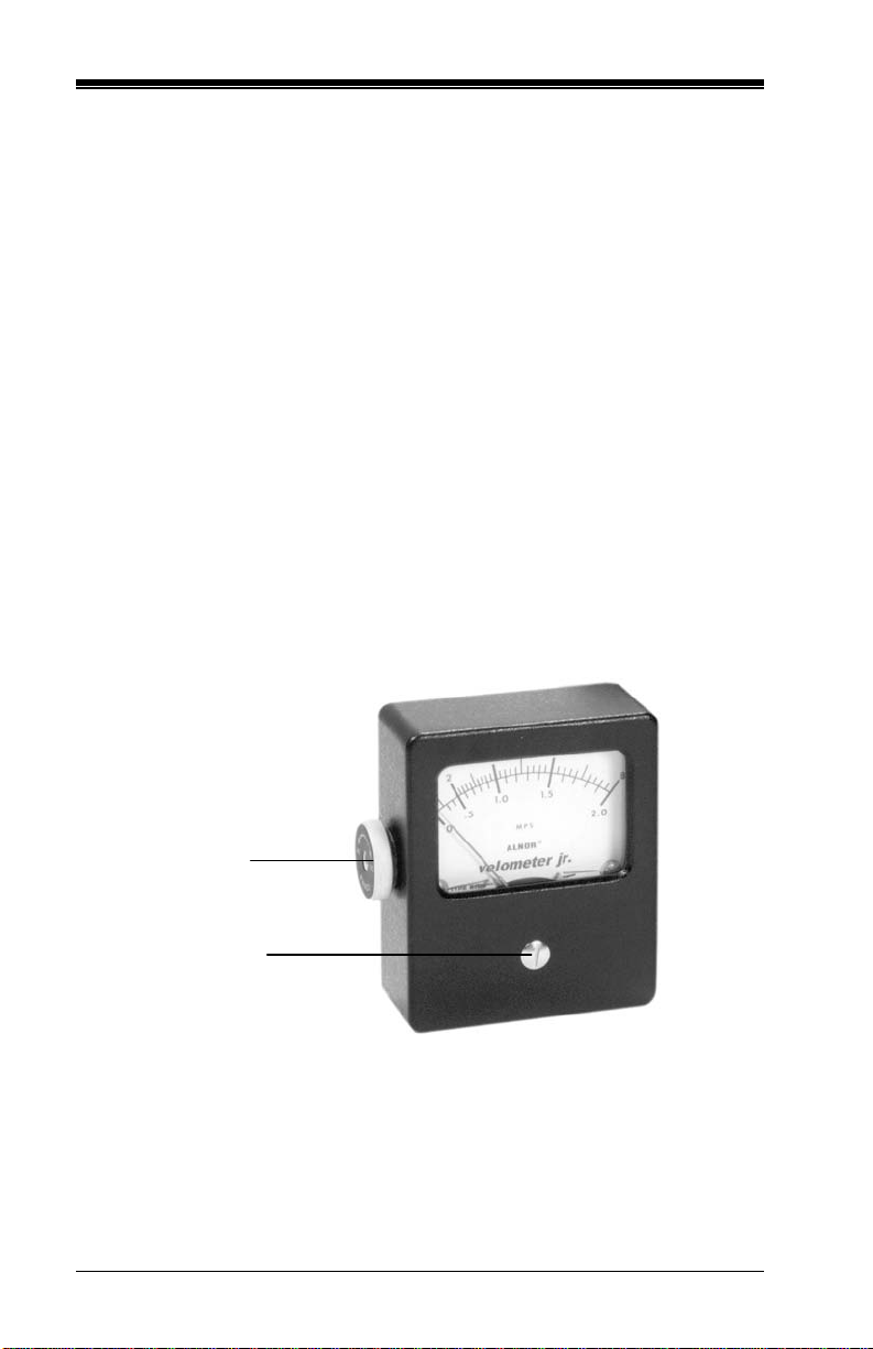
Zero Adjustment
®
Velometer Jr.®
Hold the palm of your hands over the two openings in the sides of the
Velometer Jr.
®
Anemometer and note whether the pointer indicates
Zero. If not, turn the Zero Adjuster screw on the front of the case
slightly until the pointer does read zero. (See fig. 1.)
Orifice Fitting
Zero Adjuster
Figure 1
Range Change
Change range by turning orifice fitting on double r ange i nstr um ents .
(Small orifice for high range—large orifice for low range.) (See fig.1.)
2
Page 5
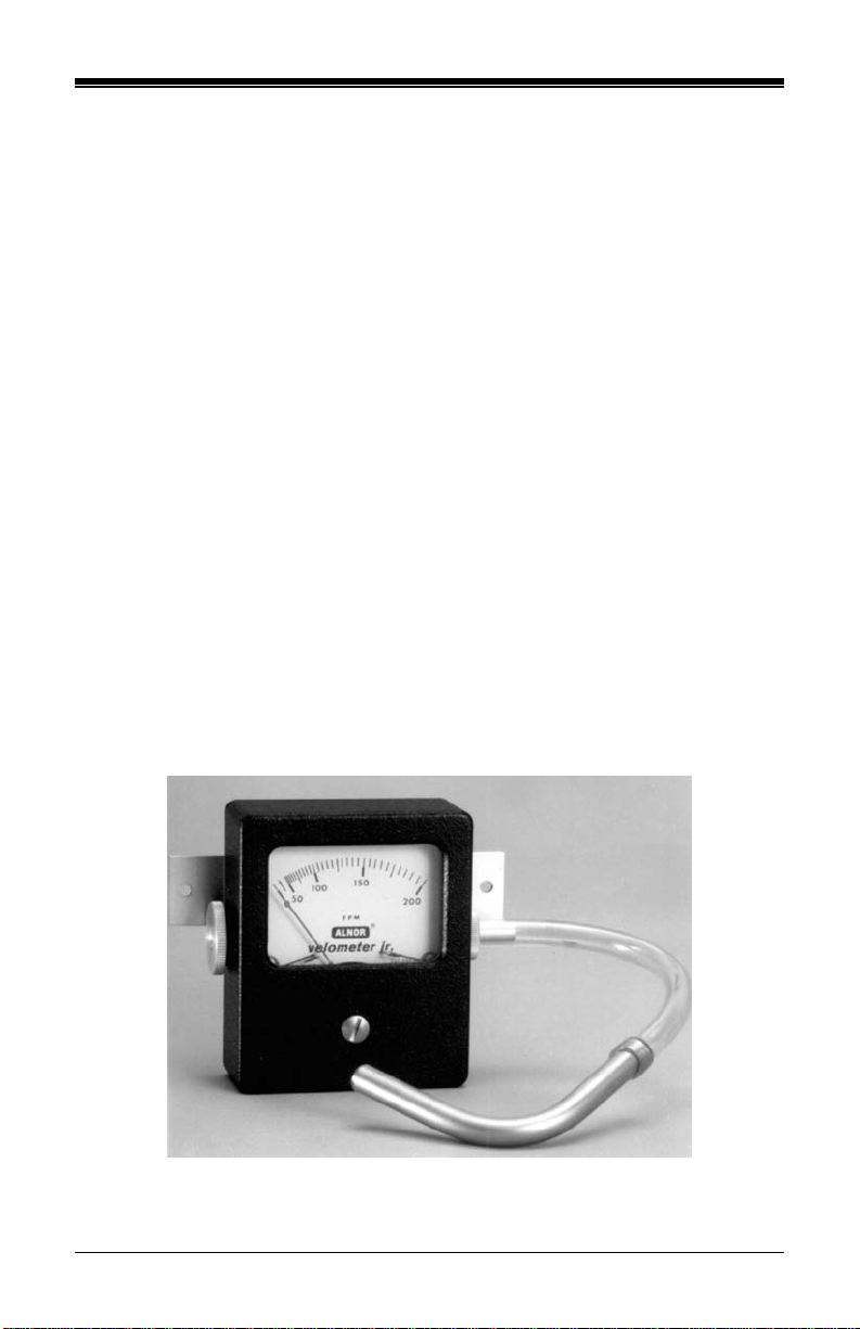
ALNOR TYPE 8125 “AirGard®”
VELOMETER JR.® ANEMOMETER
The AirGard® Face Velocity Monitor is designed to indicate, by
correlation, the average velocity at the face of a ventilation hood. To
ensure that the average face velocity indicated by the AirGard
is correct, the AirGard
can be verified with a properly calibrated thermo-anemometer. Also, the
AirGard
®
monitor should be mounted at a location where local drafts are
®
monitor should be mounted at a location where it
very low and the curved probe will not interfere with the work area.
The calibration procedure follows four basic steps:
1. Make sure the AirGard
®
monitor attachments which were shipped
with the instrument are available—the curved probe and flexible
tube.
2. Zero the AirGard
®
monitor.
3. Measure the average face velocity of the hood using a properly
calibrated thermo-anemometer.
4. Find the right location to mount the AirGard
®
monitor by moving it
along the face of the hood until the meter indicates the same value as
measured with the thermo-anemometer.
®
monitor
Figure 2
3
Page 6

Step By Step Calibration Instructions
1. Connect the curved probe to the AirGard® monitor using the flexible
tube.
2. Cover the inlet orifice on the left hand side of the AirGard
®
monitor
(the operator’s finger can be used for this purpose).
3. With the inlet covered, the AirGard
®
monitor should indicate zero
fpm. If it does not, adjust the pointer to zero using the screw on the
front of the case.
4. Using a properly calibrated thermo-anemometer, determine the
velocity through the face of the hood by taking a detailed velocity
traverse. Divide the face area of the hood into equal increments. A
six-inch grid is recommended for an accurate traverse.
5. Position the AirGard
®
monitor at a location for mounting where local
drafts are very low and the curved pr obe will not interfere with the
work area.
6. Attach the probe to the hood so the open end is inside the hood and
faces downstream.
7. Verify that the AirGard
at the face of the hood in step 4. If the reading by the AirGard
monitor does not match the reading measured in step 4, move the
AirGard
®
monitor along the face of the hood until it indicates the
®
monitor reads the same velocity measured
®
same value as measured with the thermo-anemometer.
8. When the AirGard
®
monitor’s indication matches the value measured
with the thermo-anemometer, mount it in place using the mounting
screws and the curved probe using the fitting provided.
4
Page 7

MAINTENANCE
Handle the Velometer Jr.® Anemometer as you would a watch. It is
composed of precision parts and is carefully balanced and calibrated.
If due to accident, the Velometer Jr.
®
Anemometer requires repair,
return to manufacturer for factory qual ity service. Other instrument
laboratories may not have proper calibrating equipment.
A partially plugged orifice will result in a low reading and, therefore,
we suggest occasional cleaning of the orifice. A toothpick is a good
tool for this purpose. Do not use any wire or other hard tool for this
purpose.
SERVICE INFORMATION
Service and Repair
Please return your Product Registration Card immediately. This
allows us send you service reminders, special offers, and important
information about your product.
Before sending your instrument for calibration or repair, you should
call Customer Service. The Service Department will provi de you with
the cost of service or calibration, Return Material Authorization
(RMA) number, and shipping instructions.
Please have the following information available when you call:
Owner’s Name, address, and phone number
Billing address, if different and applicable
Instrument Name or Model
Serial Number
Date of Purchase
Where Purchased
TSI recommends that you keep a ‘calibration log’ and keep all
records of service on your instrument.
5
Page 8

Instructions for Return
Send the instrument prepaid. Securely package your instrument in a
strong container surrounded by at least two inches (5 cm) of suitable
shock-absorbing material. Include the Purchase Order showing
instrument model number, cost of service and/or calibration, and the
RMA number. Mark the outside of the shipping container with the
RMA number. This will expedite processing of your instrument when
we receive it.
Please note that instruments received improperly marked or without
an accompanying Purchase Order may be return ed at your expense.
See back cover for factory addresses.
Damaged in Transit
All orders are carefully packed for shipment. On receipt, if the
shipping container appears to have been damaged during shipment,
the instrument should be thoroughly inspected. The delivering
carrier’s papers should be signed n oting the apparent damage. DO
NOT DISCARD THE BOX.
If the instrument itself has been damaged, a claim should be promptly
filed against the carrier by the custo mer. The selling agent will assist
the customer by supplying all pertinent shipping information;
however, the claim must be filed by the insured. If the instrument is
damaged beyond use, a new order should be placed with TSI while
awaiting reimbursement from the carrier for the damaged instrument.
Call TSI directly for assistance if necessary .
6
Page 9

CONTENIDO
ESPECIFICACIONES DEL VELOMETER JR. ................................... 8
CARACTERÍSTICAS ........................................................................... 9
Calibracion a Cero ......................................................................... 9
Cambio de Rangos ...................................................................... 10
VELOMETER JR. “AirGard” DE ALNOR TIPO 8125 ..................... 10
Instrucciones Detalladas de Calibracion ..................................... 11
MANTENIMIENTO ............................................................................. 12
INFORMACIÓN SOBRE SERVICI O ................................................. 13
Servicio y Reparación ................................................................. 13
Instrucciones de Devolución ....................................................... 13
Daños en Tránsito ....................................................................... 14
7
Page 10

ESPECIFICACIONES DEL VELOMETER JR.
Precision ±5% de la Escala Completa
Tiempo de Lectura 4–8 Segundos
Dimensiones 3
Lista de Modelos
3
" x 3
/4
1
" x 1
/8
1
"
/8
Número de Parte
Rango
634-110-018 0–200 y 0–800 fpm
634-110-025 0–400 y 0–1600 fpm
634-110-032 0–500 y 0–2500 fpm
634-111-013 0–1.0 y 0–4.0 mps
634-111-020 0–2.0 y 0–8.0 mps
634-111-038 0–2.5 y 0–12.5 mps
634-112-019 0–8 y 0–40 mph
AirGard Modelo 8125
634-112-080 0–200 fpm
8
Page 11

CARACTERÍSTICAS
El Velometer Jr. de Alnor es un instrumento que toma medidas
directas de la velocidad del aire.
Este instrumento de precisión le será de utilidad por muchos años si
se le proporciona con los cuidados necesarios.
Puede emplear el instrumento para tomar medidas de las velocidades
del aire de registros y parrillas, asi como también para localizar fugas
de aire. El uso del Velometer Jr. de Alnor hace que el balanceo de las
instalaciones de calefacción domésticas sean simples.
Sujete el intrumento de tal manera que el aire pase directamente por el
orificio calibrado y lea la velocidad tal y como señala el indicador.
Calibracion a Cero
Sujete el Velometer por las dos aberturas que se local izan a los lados
del instrumento, cubriéndolas con la palma de su mano, fíjese cuando
el indicador señale cero. Si no señala cero, r ote ligeramente el tornillo
ajustador que se encuentra en la parte frontal del instrumento hasta
que el indicador señale cero.
Tornillo de
Orifice
Tornillo
Adjustador
Figura 1
9
Page 12

Cambio de Rangos
Cambie los rangos cambiando la posición de los orificios en los
instrumentos de doble rango. (El orificio pequeño es para rangos altos
y el orificio grande es para rangos bajos.)
VELOMETER JR. “AirGard”
DE ALNOR TIPO 8125
El Velometer “AirGard” de Alnor fue diseñado para indicar por
correlación, los promedios de velocidad a la entrada de una caperuza
de ventilación. Para asegurarse de que el promedio de velocidades
indicada por el AirGard es la correcta, el AirGard d eberá ser montado
en un lugar donde pueda ser verificado con un termoanemómetro
debidamente calibrado. También, el AirGard deberá ser montado en
un lugar en donde las ráfagas locales sean mínimas y la sonda
curveada no interfiera con el área de trabajo.
Para los procedimientos de calibración siga los cuatro siguientes
puntos:
1. Asegúrese de que los aditamentos del AirGard con los cuales fue
empacado se encuentren a disposición: la sonda curveada y el
tubo flexible.
2. Calibre a CERO el AirGard.
3. Mida el promedio de velocidad de la entrada de la caperuza,
empleando un termoanemómetro debidamente calibrado.
4. Localize el lugar adecuado para instalar/montar el AirGard
moviendo el instrumento alrededor de la caperuza, hasta que la
lectura obtenida del AirGard sea la misma obtenida po r el
termoanemómetro.
10
Page 13

Figura 2
Instrucciones Detalladas de Calibracion
1. Conecte la sonda curveada al AirGard empleando el tub o flexible.
2. Cubra el orificio de entrada de la parte izquierda del AirGard (se
pueden usar los dedos del operador con este propósito).
3. Con el orificio de entrada cubierto, el AirGard deberá indicar
CERO fpm. Si no es de esta manera, ajuste el indicador a cero
empleando el tornillo ajustador locali zado en la parte delantera
del instrumento.
4. Empleando un anemómetro debidamente calibrado, determine la
velocidad de la entrada de la caperuza midiend o velocidades
detalladas traversas. Divida el area de entrada de la caperuza en
incrementos iguales. Se recomiendan distancias de 6 pulgadas
para una medición precisa.
5. Posicione el AirGard en un lugar en donde las ráfagas locales
sean mínimas y la sonda curveada no interfiera con el área de
trabajo.
6. Conecte la sonda a la caseta de manera que el extremo abierto se
encuentre dentro de la caseta y esté de frent e a la contracorriente.
11
Page 14

7. Verifique que la lectura del AirGard sea la misma velocidad
medida a la entrada de la caperuza del paso 4. Si la lectur a del
AirGard no corresponde a la lectura tomada en el paso 4, mueva
el instrumento a lo largo de la caperuza hasta que encuentre el
punto en donde las lecturas sean iguales a las del
termoanemómetro.
8. Cuando las indicaciones del AirGard corr espondan a los valores
medidos con el termoanemómetro, instale el instrumento
empleando los tornillos de montaje, y la sonda curveada,
empleando los aditamentos proporcionados.
MANTENIMIENTO
Maneje este instrumento como lo haría con un reloj de mano. Está
construido de partes de precisión y ha sido cuidadosamente calibrado
y balanceado.
Si debido a un accidente, requiere de r eparación, envíelo al fabricante
para que obtenga un servicio de calidad. Cualquier otro laboratorio de
instrumentación puede no tener el equipo adecuado de calibración.
Si tiene un orificio parcialmente tapado, obtendrá lecturas bajas y por
lo tanto, sugerimos que limpie el orificio de vez en cuando. Un palillo
de dientes puede ser una herramienta adecuada par a lograr dicho
propósito. No utilize ningún tipo de alambre o herramientas pesadas
con el mismo propósito.
12
Page 15

INFORMACIÓN SOBRE SERVICIO
Servicio y Reparación
Sírvase devolver su Tarjeta de registro d el producto inmediatamente.
Esto nos permitirá enviarle recordatorios d e ser vicio, ofertas
especiales e información importante sobre su prod ucto.
Antes de enviar el producto para su calibración o reparación, deberá
llamar al Servicio de atención al cliente de TSI. El Departamento de
servicio le proporcionará el valor d el costo del servicio o de la
calibración, el número de Autorización de devolución de material
(RMA, por sus siglas en inglés) y las instrucciones de envío.
Sírvase tener la información siguiente disponible al realizar la
llamada:
Nombre del propietario, dirección y número de teléfono
Dirección de envío de la factura, si fuera di f er ente y aplicable
Nombre del instrumento o modelo
Número de serie
Fecha de compra
Lugar de compra
TSI le recomienda que mantenga un ‘registro de calibración’ y que
guarde todos los documentos de servicio del instrumento.
Instrucciones de Devolución
Envíe el instrumento con el franqueo pre-pagado. Embale el
instrumento con seguridad en un contenedor resistente envuelto en, al
menos, 2 pulgadas (5 cm) de material de protección contra golpes
apropiado. Incluya la Orden de compra con el número de modelo del
instrumento, el costo del servicio y/o calibración, y el número de
Autorización de devolución de material (R MA). Marque el exterior
del contenedor de envío con el n úmero de RMA. Esto acelerará el
procesamiento de su instrumento cuando lo recibamos.
Tenga en cuenta que los instrumentos que se reciban marcados de
manera inapropiada o sin la correspondiente Orden de compra
podrían ser devueltos con los gastos a su cargo. Vea la cubierta
trasera de este manual para obtener las direcciones de fábrica.
13
Page 16

Daños en Tránsito
Todos los pedidos son embalados cuidadosamente para su envío. Una
vez recibido, si el contenedor de envío aparenta haber sido dañado
durante su envío, el instrumento deberá ser inspeccionado
meticulosamente. Los documentos de la compañía tran sportista
deberán firmarse haciendo constar el daño aparente. NO SE
DESHAGA DE LA CAJA.
Si el instrumento ha sufrido daños, el cliente deberá presentar una
queja inmediatamente contra la compañía transportista. El agente
vendedor asistirá al cliente proporcionando toda la información de
envío pertinente; sin embargo, la reclamación d eberá ser presentada
por la parte asegurada. Si el instrumento está d añado sin remedio, se
deberá hacer un nuevo pedido a TSI mientras se espera el reembolso
por parte de la compañía transportista por el instrumento dañado.
Llame a TSI directamente si necesita asistencia.
14
Page 17

TABLE DES MATIÈRES
FICHE TECHNIQUE .......................................................................... 16
CARACTÉRISTIQUES ...................................................................... 17
Réglage du Zéro .......................................................................... 17
Changement d’Amplitude ............................................................ 18
ALNOR TYPE 8125 “AirGard” VELOMETER JR. .......................... 18
Proceudre de Calibrage .............................................................. 19
ENTRETIEN ....................................................................................... 20
RENSEIGNEMENTS DE SERVICE .................................................. 21
Service et Réparations ................................................................ 21
Instructions de Retour à l’Usine .................................................. 21
Dommages en Transit ................................................................. 22
15
Page 18

FICHE TECHNIQUE
Precision ±5% de la valeur inscrite
Temps De Lecture 4 à 8 Secondes
Dimensions 9.525 CM x 7.93 CM x 2.858 CM
Liste des Modeles
No de Serie
634-110-018 0–200 et 0–800 fpm
634-110-025 0–400 et 0–1600 fpm
634-110-032 0–500 et 0–2500 fpm
634-111-013 0–1.0 et 0–4.0 mps
634-111-020 0–2.0 et 0–8.0 mps
634-111-038 0–2.5 et 0–12.5 mps
634-112-019 0–8 et 0–40 mph
AirGard Model 8125
634-112-080 0–200 fpm
Capacite de Mesure
16
Page 19

Ajustement du
CARACTÉRISTIQUES
Le Velometer Jr. d’Alnor est un appareil de mesure de la vitesse de
l’air à lecture directe.
Cet instrument de précision et sa fabrication de qualité vous
donneront entière satisfaction pen dant de nombreuses années s’il est
utilise avec soin.
Vous pouvez utiliser cet appareil pour mesurer la vitesse
d’écoulement de l’air â la sortie d’une bouche de ventilation ou pour
localiser des courants d’airs. L’équilibrage d’une installation de
chauffage devient simple en utilisant le “Velo meter Jr.” d’Alnor.
Positionnez l’instrument de facon à ce que l’air passe directement par
l’orifice de mesure et lisez la vitesse indiquée p ar l’index.
Réglage du Zéro
Obstruez les deux orifices de chaque côté d u “Velometer Jr.” avec la
paume de la main et vérifiez si l’index indique bien zéro. Si tel n’est
pas le cas, tournez doucement la vis de mise à zéro située sur l e
devant de l’appareil jusqu’à ce que l’index soit sur zéro.
Raccord de
l’Orifice
Zéro
Figure 1
17
Page 20

Changement d’Amplitude
Sur les appareils à double capacité de mesure, vous pouvez changer
de calibrage en tournant la mollette de réglage de dimension de
l’orifice. (Petit orifice pour une grande amplitude—Grand orifice
pour une petite amplitude).
ALNOR TYPE 8125
“AirGard” VELOMETER JR.
Le model “AirGard” d’Alnor a été conçu pour indiquer, par
correlation, la vitesse moyenne á la sortie d ’une hotte de ventilation.
Pour être sûr que la vitesse moyenne de sortie indiquée est correcte,
“l’AirGard” doit être installé à un endr oit ou la vitesse peut être
verifiée avec un thermoanémomètre convenablement calibré. De pl us
l’AirGard doit être installé à un endroit ou les courants locaux sont
très faibles et de façon à ce que la sonde courbe ne gêne pas la zone
de travail.
La procédure de calibrage passe par les quatres ét apes suivantes:
1. Verifiez que les accessoires AirGard ont bien été liv r és avec
l’appareil (sonde courbe et tubes souples).
2. Ajustez l’AirGard sur zéro.
3. Mesurez la vitesse moyenne de sortie d’air avec le
thermoanémomètre.
4. Trouvez le bon endroit pour installer l’AirGard en le déplacant le
long de la hotte Jusqu’à ce que l’appareil indique la valeur
mesurée avec le thermoanémomètre.
18
Page 21

Figure 2
Proceudre de Calibrage
1. Connectez la sonde courbe à l’AirGard en utilisant les tubes
souples.
2. Obstruez l’orifice d’entrée situe sur la gauche de l’AirGard.
(l’operateur pourra utiliser son doigt pour cela).
3. Une fois l’orifice d’entrée obstrué, l’AirGard doit indiquer zéro
fpm. Si tel n’est pas le cas, reglez l’index sur zéro en tournant la
vis de réglage située sur le devant de l’appareil.
4. En utilisant un thermoanémomètre convenablement calibré,
determinez la vitesse de l’air qui passe à travers la hotte
en effectuant une traverse de vitesse
précise. Divisez la surface de
sortie de la hotte en parties égales. Nous reco mmendons un
quadrillage de six inch (15 cm) pour obtenir une traverse précise.
5. Installez l’AirGard à un endroit ou les courants locaux sont très
faibles et où la sonde courbe ne gêne pas la zone de travail.
6. Attachez la sonde à la hote de facon à ce que la p artie ouverte de
la sonde soit à l’interieur de la ho tte et en aval du courrant d’air.
7. Verifez que l’AirGard indique la même vitesse d’écoulement que
celle mesurée à la sortie de la hotte à l’étape 4. Si la valeur
mesurée par l’AirGard n’est pas la même que celle mesurée à
l’etape 4, déplacez l’AirGard le long de la hotte jusqu’à ce qu’il
indique la même valeur que celle relevée avec le
thermoanémomètre.
19
Page 22

8. Quand la mesure de l’AirGard correspond à la valeur mesurée par
le thermoanémomètre, installez le définitivement en utilisant les
vis de montage. Installez la sonde courbe en utilisant le materiel
de montage fourni.
ENTRETIEN
Manipulez cet appareil comme si vous manipuleriez une mont r e. Il est
compose de pièces de précision et a été equilibré et calibré avec les
plus grands soins.
Si par accident, des réparations étaient nécessai r es, renvoyez
l’appareil au service apres vente d’usine du fabricant. D’autres
laboratories de réparation n’auraient pas forcement les appareils de
calibrage nécessaires.
Un orifice partiellement obstrué donnera des val eurs de mesure
minorées, c’est pourquoi nous recommendons un nettoyage régulier
de l’orifice. Pour cela, vous pouvez utiliser un cure-dent. Ne jamais
utiliser de fil de fer ou n’importe quel autre outil trop dur pour le
nettoyage de l’orifice.
20
Page 23

RENSEIGNEMENTS DE SERVICE
Service et Réparations
Prière de retourner sans délai votre carte d’enregistrement de produit,
ce qui permettra à TSI de vous faire parvenir des rappels de service,
des offres spéciales et des renseignements importants concernant
votre produit.
Avant d’expédier votre instrument pour étalonnage ou pour
réparation, il est préférable de téléphoner au Service à la clientèle
d’TSI, qui vous communiquera le coût de la réparation ou de
l’étalonnage, le numéro d’autorisation de retour de matériel (RMA) et
les instructions de retour à l’usine.
Prière d’avoir les renseignements suivants sous la main lors de votre
appel :
Nom, adresse et numéro de téléphone du propriétaire
Adresse de facturation, si différente et applicable
Nom ou modèle de l’instrument
Numéro de série
Date d’achat
Place d’achat
TSI vous recommande de tenir un « registre d’étalonnage » et de
conserver tous les dossiers de service concern ant votre instrument.
Instructions de Retour à l’Usine
Expédier l’instrument port payé. Emballer soigneu sement
l’instrument dans un contenant robuste, enveloppé d’au moins 5 cm
(2 po) de matériel amortisseur approprié. Inclure le bon de commande
indiquant le numéro de modèle de l’instrument, le coût du service et
(ou) de l’étalonnage et le numéro d’autorisation de retour de matériel
(RMA). Indiquer le numéro RMA au crayon feutre sur l’extérieur du
contenant d’expédition, ce qui accélérera le traitement dès réception
de votre instrument.
Prière de noter que les instruments reçus sans les indications
appropriées ou sans bon de commande pourraient être retournés à vos
frais. Voir l’adresse de l’usine sur la co uverture arrière de ce manuel.
21
Page 24

Dommages en Transit
Toutes les commandes sont soigneusement emballées avant
l’expédition. Dès réception, si le contenant d’expédition semble avoir
été endommagé pendant le transport, l’instrument doit être examiné
avec soin. Indiquer les dommages apparents sur les documents du
transporteur livreur avant de les signer. NE PAS JETER LA BOÎTE.
Si l’instrument a été endommagé, le client doit immédiatement
présenter une réclamation au transporteur. L’agent vendeur aidera le
client en fournissant tous les détails d’expédition pertinents; la
réclamation, cependant, doit être déposée p ar l’assuré. Si l’instrument
est endommagé au point d’être inutilisable, le client devrait passer
une nouvelle commande auprès d’TSI en attendant d’être remboursé
par le transporteur pour l’instrument endommagé.
Appeler TSI directement pour obtenir de l’aide, au besoin.
22
Page 25

VELOMETER JR.
®
SPECIFICATIONS
Accuracy ±5% of Full Scale
Read-out Time 4–8 Seconds
Dimensions 3
3
" x 3
/4
1/
" x 1
8
1
/8
List of Models
"
Part Number
Range
634-110-018 0–200 and 0–800 fpm
634-110-025 0–400 and 0–1600 fpm
634-110-032 0–500 and 0–2500 fpm
634-111-013 0–1.0 and 0–4.0 mps
634-111-020 0–2.0 and 0–8.0 mps
634-111-038 0–2.5 and 0–12.5 mps
634-112-019 0–8 and 0–40 mph
AirGard® Model 8125
634-112-080 0–200 fpm
Page 26

Alnor Products, TSI Incorporated –
500 Cardigan Road, Shoreview, MN 55126-3996 U.S.A
USA Tel: +1 800 874 2811 E-mail: customerservice@alnor.com
Contact your local ALNOR Distributor or visit our website www.alnor.com for more detailed s pec ifications.
P/N 116049007-09 Copyright © 2010 by TSI Incorporated Printed in U.S.A.
 Loading...