

Page 1

AIRPRO®
SOLUTIONS
MODELS AP500/AP800
OPERATION/USER MANUAL
P/N 6010062, REVISION A
FEBRUARY 2017
Find Quality Products Online at: sales@GlobalTestSupply.com
www.GlobalTestSupply.com
Page 2

Seller warrants the goods, excluding software, sold hereunder, under normal use and
service as described in the operator's manual, to be free from defects in workmanship
and material for 24 months, or if less, the length of time specified in the operator's
manual, from the date of shipment to the customer. This warranty period is inclusive of
any statutory warranty. This limited warranty is subject to the following exclusions and
exceptions:
Warranty
a. Hot-wire or hot-film sensors used with research anemometers, and certain other
components when indicated in specifications, are warranted for 90 days from the
date of shipment;
b. Carbon monoxide (CO) Electro-chemical sensors are warranted for 12 months
from the date of shipment.
c. Pumps are warranted for hours of operation as set forth in product or operator’s
manuals;
d. Parts repaired or replaced as a result of repair services are warranted to be free
from defects in workmanship and material, under normal use, for 90 days from the
date of shipment;
e. Seller does not provide any warranty on finished goods manufactured by others or
on any fuses, batteries or other consumable materials. Only the original
manufacturer's warranty applies;
f. This warranty does not cover calibration requirements, and seller warrants only
that the instrument or product is properly calibrated at the time of its manufacture.
Instruments returned for calibration are not covered by this warranty;
g. This warranty is VOID if the instrument is opened by anyone other than a factory
authorized service center with the one exception where requirements set forth in
the manual allow an operator to replace consumables or perform recommended
cleaning;
h. This warranty is VOID if the product has been misused, neglected, subjected to
accidental or intentional damage, or is not properly installed, maintained, or
cleaned according to the requirements of the manual. Unless specifically
authorized in a separate writing by Seller, Seller makes no warranty with respect to,
and shall have no liability in connection with, goods which are incorporated into
other products or equipment, or which are modified by any person other than Seller.
The foregoing is IN LIEU OF all other warranties and is subject to the LIMITATIONS
stated herein. NO OTHER EXPRESS OR IMPLIED WARRANTY OF FITNESS FOR
PARTICULAR PURPOSE OR MERCHANTABILITY IS MADE. WITH RESPECT TO
SELLER’S BREACH OF THE IMPLIED WARRANTY AGAINST INFRINGEMENT,
SAID WARRANTY IS LIMITED TO CLAIMS OF DIRECT INFRINGEMENT AND
EXCLUDES CLAIMS OF CONTRIBUTORY OR INDUCED INFRINGEMENTS.
BUYER’S EXCLUSIVE REMEDY SHALL BE THE RETURN OF THE PURCHASE
PRICE DISCOUNTED FOR REASONABLE WEAR AND TEAR OR AT SELLER’S
OPTION REPLACEMENT OF THE GOODS WITH NON-INFRINGING GOODS.
TO THE EXTENT PERMITTED BY LAW, THE EXCLUSIVE REMEDY OF THE USER
OR BUYER, AND THE LIMIT OF SELLER'S LIABILITY FOR ANY AND ALL LOSSES,
Find Quality Products Online at: sales@GlobalTestSupply.com
INJURIES, OR DAMAGES CONCERNING THE GOODS (INCLUDING CLAIMS
iii
www.GlobalTestSupply.com
Page 3

Contents
Manual History .................................................................................................. i
Warranty ..........................................................................................................iii
Safety ..............................................................................................................vii
Bluetooth® Safety and Compliance .............................................................. vii
Battery Safety and Disposal .......................................................................... ix
Description of Labels and Markings .............................................................. ix
Warning ...................................................................................................... ix
Caution ....................................................................................................... ix
RoHS .............................................................................................................. x
CE ................................................................................................................... x
CHAPTER 1 Parts Identification .....................................................................1
CHAPTER 2 Set Up ..........................................................................................5
Supplying Power to the Instrument ................................................................5
Installing the Battery ....................................................................................5
Using the AC Adapter .................................................................................6
Using a Memory Card .....................................................................................6
Connecting Probes .........................................................................................7
Using Extensions ............................................................................................7
Using Locator Clips ........................................................................................7
Using the Pressure Ports (Model AP800 only) ...............................................8
Connecting the Static Pressure Probe ...........................................................8
Connecting an Optional Pitot Probe ...............................................................9
Using the Carrying Cases and Protective Probe Case ..................................9
CHAPTER 3 Operation ..................................................................................11
Instrument Operation ....................................................................................11
Keypad Functions......................................................................................11
Model AP800 Differential Pressure Auto-Zero ..........................................11
Common Terms ............................................................................................12
Common Symbols .....................................................................................14
AirPro Mobile ................................................................................................14
Smartphone Requirements .......................................................................15
Download AirPro Mobile ............................................................................15
Create an Account ....................................................................................15
Log in to AirPro Mobile ..............................................................................16
Connect AirPro Mobile with Probe ............................................................16
Available Probes ....................................................................................17
Probe Specific Configurations ...................................................................17
Set up the Probe ....................................................................................17
Show a Target Value .............................................................................18
Data Logging .............................................................................................18
Logging ..................................................................................................19
Start Logging ..........................................................................................19
Data Logging Settings ...............................................................................20
Set Up Logging ......................................................................................20
Data Files ..................................................................................................20
Data Files ...............................................................................................21
v
Find Quality Products Online at: sales@GlobalTestSupply.com
www.GlobalTestSupply.com
Page 4

View Data File Information .................................................................... 21
Delete Data Files ................................................................................... 22
Share Data Files ................................................................................... 22
Create a New Test ................................................................................ 23
Workflows ................................................................................................. 23
Conducting Workflow ............................................................................ 23
Select Duct Type ................................................................................... 24
Duct Traverse Setup ............................................................................. 24
Global Setup, Units of Measure and Standard/Actual Setup ................... 27
Units of Measure ................................................................................... 27
Standard/Actual Setup .......................................................................... 28
User Profile ............................................................................................ 28
Saved Sample Notification .................................................................... 29
CHAPTER 4 Maintenance ............................................................................. 31
Recalibration ................................................................................................ 31
Cases ........................................................................................................... 31
Storage ........................................................................................................ 31
CHAPTER 5 Troubleshooting ...................................................................... 33
APPENDIX A Specifications ......................................................................... 35
Model AP500 AirPro Mobile with Probes ..................................................... 35
Wireless Connectivity Range (line of sight) .......................................... 35
Model AP500 ............................................................................................... 35
Barometric Pressure ............................................................................. 35
Instrument Temperature Range ............................................................ 35
Display Interface ................................................................................... 35
External Meter Dimensions ................................................................... 35
Meter Weight with Batteries .................................................................. 35
Power Requirements ............................................................................. 35
Battery Life ............................................................................................ 35
Model AP500 AirPro Measurement Probes................................................. 36
Velocity (VT-S, VT-A, VTH-S, VTH-A) .................................................. 36
Temperature (VT-S, VT-A, VTH-S, VTH-A, TH-S) ................................ 36
Relative Humidity (VTH-S, VTH-A, TH-S) ............................................. 36
Straight Probe Dimensions (VT-S, VTH-S, TH-S) ................................ 36
Articulating Probe Dimensions (VT-A, VTH-A) ..................................... 36
Probe Extension Dimensions (800529) ................................................ 36
Model AP800 ............................................................................................... 37
Wireless Connectivity Range (line of sight) .......................................... 37
Static / Differential Pressure .................................................................. 37
Velocity (Pitot Probe) ............................................................................ 37
Barometric Pressure ............................................................................. 37
Instrument Temperature Range ............................................................ 37
Display Interface ................................................................................... 37
External Meter Dimensions ................................................................... 37
Meter Weight ......................................................................................... 37
Power Requirements ............................................................................. 37
Battery Life ............................................................................................ 37
Supported Units of Measure and Defaults................................................... 38
Language Options ....................................................................................... 38
vi AirPro
Find Quality Products Online at: sales@GlobalTestSupply.com
www.GlobalTestSupply.com
®
Instrument Models AP500/AP800
Page 5

W A R N I N G
The instrument must be used in the manner described in this manual. Failure
to follow all of the procedures described in this manual can result in serious
injury to you or can cause irrevocable damage to the instrument. There are
no user-serviceable parts inside the instrument. Refer all repairs to a
qualified factory-authorized technician.
W A R N I N G
Do not use the instrument or probes near hazardous voltage sources since
serious injury could result.
Note
This device may not cause interference; this device must accept any
interference, including interference that may cause undesired operation of
the device.
l’appareil ne doit pas produire de brouillage; l’appareil doit accepter tout
brouillage radioélectrique subi, même si le brouillage est susceptible d’en
compromettre le fonctionnement.
Safety
This section provides instructions to ensure safe and proper handling of the
AirPro® Products.
Bluetooth® Safety and Compliance
This product uses Bluetooth® Low Energy v.4.0 to transmit with software
applications.
Hereby, TSI Inc. declares that this Bluetooth® Low Energy test and
measurement instrument is in compliance with Directive 2014/53/EC.
BLE Transmit Power Rating is +3 dBm, MAX @ 2.4 – 2.5 GHz
Find Quality Products Online at: sales@GlobalTestSupply.com
www.GlobalTestSupply.com
vii
Page 6

Note
This equipment has been tested and found to comply with the limits for a
Class B digital device, pursuant to part 15 of the FCC Rules. These limits are
designed to provide reasonable protection against harmful interference in a
residential installation. This equipment generates, uses, and can radiate
radio frequency energy and, if not installed and used in accordance with the
instructions, may cause harmful interference to radio communications.
However, there is no guarantee that interference will not occur in a particular
installation. If this equipment does cause harmful interference to radio or
television reception, which can be determined by turning the equipment off
and on, the user is encouraged to try to correct the interference by one or
more of the following measures:
• Reorient or relocate the receiving antenna.
• Increase the separation between the equipment and receiver.
• Connect the equipment into an outlet on a circuit different from that to
which the receiver is connected.
• Consult the dealer or an experienced radio/TV technician for help.
Note
This device complies with Industry Canada licence-exempt RSS standard(s).
Operation is subject to the following two conditions: (1) this device may not
cause interference, and (2) this device must accept any interference,
including interference that may cause undesired operation of the device.
W A R N I N G
Changes or modifications not expressly approved by the party responsible
for compliance could void the user's authority to operate the equipment.
Find Quality Products Online at: sales@GlobalTestSupply.com
viii AirPro
www.GlobalTestSupply.com
®
Instrument Models AP500/AP800
Page 7

W A R N I N G
DO NOT abuse the battery in any way as the battery may rupture or
catch fire.
Use only TSI supplied batteries (Part number 800532) in this instrument.
DO NOT use a substitute or non-rechargeable battery in this instrument.
DO NOT short-circuit, incinerate, dismantle or mutilate Lithium ion
batteries.
DO NOT expose to water or heat.
Do charge the battery in the proper charging conditions
DO NOT use equipment if battery becomes hot. IMMEDIATELY turn off
the equipment if battery becomes hot to the touch.
DO NOT use any battery which shows signs of damage, such as bulging,
swelling, a swollen plastic wrap, liquid in the plastic wrap, etc.
W A R N I N G
Warning means that unsafe use of the instrument could result in serious
injury to you or cause irrevocable damage to the instrument. Follow the
procedures prescribed in this manual to use the instrument safely.
C a u t i o n
Caution means be careful. It means if you do not follow the procedures
prescribed in this manual you may do something that might result in
equipment damage, or you might have to take something apart and start over
again. It also indicates that important information about the operation and
maintenance of this instrument is included.
Battery Safety and Disposal
This instrument uses a rechargeable Lithium ion battery with built-in
protection against fire and explosion hazard. Always dispose of Li-ion
batteries and transport Li-ion batteries in compliance with regional
regulations.
Description of Labels and Markings
This section acquaints you with the advisory and identification labels on the
instrument and used in this manual to reinforce the safety features built into
the design of the instrument. It also identifies instrument markings.
Warning
Caution
Find Quality Products Online at: sales@GlobalTestSupply.com
www.GlobalTestSupply.com
Safety ix
Page 8

Serial Number Label
WEEE marking indicates item is non-
disposable and must be recycled.
RoHS
CE
AirPro series instruments are RoHS compliant.
AirPro series instruments are CE compliant.
Find Quality Products Online at: sales@GlobalTestSupply.com
x AirPro
www.GlobalTestSupply.com
®
Instrument Models AP500/AP800
Page 9

Description
Part number
Reference picture
For use
with
Instrument for measuring
differential pressure and
barometric pressure.
AP800
AP800
Instrument for use with
probes and for measuring
barometric pressure.
AP500
VTH-S,
VTH-A,
VT-S, VT-A,
TH-S
Articulated probe for
measuring velocity,
temperature, and humidity.
VTH-A
AP500
Straight probe for
measuring velocity,
temperature, and humidity.
VTH-S
AP500
Articulated probe for
measuring velocity and
temperature.
VT-A
AP500
Straight probe for
measuring velocity and
temperature.
VT-S
AP500
Straight probe for
measuring temperature and
humidity.
TH-S
AP500
Probe Extension—12 in.
(305 mm); used to extend
the reach of the probe. The
maximum number of
extensions that can be
stacked together is three.
800529
AP500 and
probe
Models
VTH-S,
VTH-A,
VT-S, VT-A,
TH-S
C H A P T E R 1
Parts Identification
The items listed below may be received as part of an individual product
package or as a bundled package of several products.
Carefully unpack the instrument(s) and accessories from the/their shipping
container(s). Check the individual parts against the list of components below.
If anything is missing or damaged, notify TSI immediately.
Find Quality Products Online at: sales@GlobalTestSupply.com
www.GlobalTestSupply.com
1
Page 10

Description
Part number
Reference picture
For use
with
Carrying case, small;
capable of holding
1 instrument, 1 probe and
3 extensions.
800534
AP500 or
AP800
Carrying case, large;
capable of holding
2 instruments, 2 probes and
3 extensions.
800535
AP500 or
AP800
Probe protective case.
800536
VTH-S,
VTH-A,
VT-S,
VT-A, TH-S
Static Pressure Probes and
Tubing Kit—contains two
static pressure probes and
two 4 ft. (1.2 m) lengths of
tubing.
800533
AP800
Pitot probe.
634634000
634634001
634634002
634634003
634634005
634634004
Pitot probe (5/16" (8 mm) diameter) - 12" (30 cm)
Pitot probe (5/16" (8 mm) diameter) - 18" (46 cm)
Pitot probe (5/16" (8 mm) diameter) - 24" (61 cm)
Pitot probe (5/16" (8 mm) diameter) - 36" (91 cm)
Pitot probe (5/16" (8 mm) diameter) - 60" (152 cm)
Telescoping pitot probe - 8" to 38" (20 cm to 96 cm)
AP800
Locator clips provide a
visual indicator of how far
the probe is inserted into
duct. Quantity 20.
800537
VTH-S,
VTH-A,
VT-S,
VT-A,
TH-S
Lithium-ion Rechargeable
Battery.
800532
AP800,
AP500
Find Quality Products Online at: sales@GlobalTestSupply.com
2 AirPro® Instrument Models AP500/AP800
www.GlobalTestSupply.com
Page 11

Description
Part number
Reference picture
For use
with
Universal AC/DC adapter
for charging the battery
while it is in the instrument.
800531
AP800,
AP500
External battery charger.
800530
AP500,
AP800
Duct plugs, 3/8" (9.5 mm)
diameter—1000 pieces.
634650002
AP500,
AP800
Duct plugs, 3/8" (9.5 mm)
diameter—5000 pieces.
634650003
AP500,
AP800
Find Quality Products Online at: sales@GlobalTestSupply.com
Chapter 1: Parts Identification 3
www.GlobalTestSupply.com
Page 12

W A R N I N G
This instrument uses a rechargeable Lithium ion battery with built-in
protection against fire and explosion hazard. Use only TSI supplied batteries
(TSI part number 800532) in this instrument. DO NOT use a substitute or
non-rechargeable battery. Always dispose of Li-ion batteries in compliance
with regional requirements. DO NOT abuse the battery in any way as the
battery may rupture or catch fire.
DO NOT short circuit, incinerate, dismantle, or mutilate Lithium ion
batteries.
DO NOT expose to water or heat.
DO charge the battery in the proper charging conditions
DO NOT use equipment if battery becomes hot. IMMEDIATELY turn off
the equipment if battery becomes hot to the touch.
DO NOT use any battery which shows signs of damage, such as bulging,
swelling, a swollen plastic wrap, liquid in the plastic wrap, etc.
C H A P T E R 2
Set Up
Supplying Power to the Instrument
These instruments can be powered with a battery or with the AC adapter.
Installing the Battery
Insert the battery as indicated by the diagram located on the inside of the
battery compartment. The Lithium-ion battery is a rechargeable battery. When
a new battery is fully charged and used in the AP500, it will last for more than
8 hours at 100 ft/min (0.5 m/s) and 77°F (25°C). Runtime will be shortened at
colder temperatures and higher flows. With Model AP800 new fully charged
batteries typically last more than 32 hours.
Find Quality Products Online at: sales@GlobalTestSupply.com
5
www.GlobalTestSupply.com
Page 13

C a u t i o n
Use only the AC adapter provided (TSI part number 800531) and do not
substitute another adapter or use a computer to supply power. Use of an
incorrect power supply can cause the measurements to be inaccurate.
Note
The battery must be installed before the AC/DC adapter is plugged in to
initiate recharging. If the AC/DC adapter is plugged in before the battery is
installed then the battery will not recharge.
Using the AC Adapter
The AC adapter can be used to power the instrument and to charge the
battery. Be sure to provide the correct voltage and frequency, which is
marked on the back of the AC adapter. When the battery needs to be
recharged, plug in the AC/DC adapter. Observe the orange LED which
indicates the battery is in the process of charging. The LED will turn off once
the battery is completely charged.
Using a Memory Card
The instrument allows for the use of a micro SDHC card to provide additional
data storage. The memory card must be purchased separately. It must be
preformatted with a FAT32 file system with a minimum of 100 MB space free.
The memory card plugs into the slot next to the USB port.
Find Quality Products Online at: sales@GlobalTestSupply.com
6 AirPro® Instrument Models AP500/AP800
www.GlobalTestSupply.com
Page 14

W A R N I N G
DO NOT use more than 3 feet of extensions or the measurement will become
inaccurate.
Note
For temperature and humidity measurements, make certain that at least
3 inches (7.5 cm) of the probe is in the flow. This will allow the temperature
and humidity sensors to be in the air stream.
Connecting Probes
The probes for the Model AP500 instrument screw into the top of the handle.
Insert the probe into the knurled nut and hold it tight. Then twist the knurled
nut until tight. It should take only 5 to 6 turns and a hard stop will indicate
when it is tight. You can orient the probe 360 degrees by loosening the nut,
twisting the probe and retightening the nut. The probe for Model AP800 is
integrated into the instrument and is not removable.
Using Extensions
Extensions can be used to extend the reach of the probe by up to 3 feet.
Using Locator Clips
Locator clips snap onto the probes and slide easily along the probe body.
They are used to set the depth at which the probe is to be inserted into an
airstream.
Find Quality Products Online at: sales@GlobalTestSupply.com
Chapter 2: Set Up 7
www.GlobalTestSupply.com
Page 15

W A R N I N G
DO NOT expose the pressure ports to more than 190 inH
2
O (47280 Pa)
pressure differential. This will damage the sensor and make the measurement
inaccurate.
The Model AP800 can
be used with the Static
Pressure probe by
connecting to the
“+” port on the
instrument using
pressure tubing. The
Static Pressure probe is
used to measure the
duct static pressure and
features a magnet which
holds the probe to the
ductwork.
Using the Pressure Ports (Model AP800 only)
The Model AP800 has pressure ports that can be used to measure static and
differential pressures. The “+” port connects to the higher pressure and the “-”
port connects to the lower pressure. When the pressure is connected the
same way the tubes are marked, the meter displays a positive number. When
the pressure is reversed, the meter displays a negative number.
Connecting the Static Pres s u r e Probe
Find Quality Products Online at: sales@GlobalTestSupply.com
8 AirPro® Instrument Models AP500/AP800
www.GlobalTestSupply.com
Page 16

Note
The pitot velocity needs a valid temperature to perform the standard or
actual velocity correction. The temperature setting is controlled in the AirPro
Mobile application, see Chapter 4.
Total pressure hole
Static pressure holes
Static pressure port
connects to “-” input on
instrument.
Total pressure port
connects to “+” input on
instrument.
Connecting an Optional Pit o t Probe
When connected to a pitot probe, air velocity or air volume can be measured.
A pitot probe can be connected to the “+” and “-” pressure ports on the Model
AP800 using two pieces of tubing of equal length. The total pressure port of
the pitot probe connects to the “+” port on the instrument, and the static
pressure port of the pitot probe connects to the “-” port on the instrument.
Using the Carrying Cases and Protective
Find Quality Products Online at: sales@GlobalTestSupply.com
Probe Case
The carrying cases can be used to store and transport the instruments,
probes and accessories. The small case accommodates one instrument and
one probe while the larger case accommodates two instruments and two
probes. The probe protective case will accommodate any of the probe
variants. Use the protective probe case to transport and store the probe when
it is not in operation.
Chapter 2: Set Up 9
www.GlobalTestSupply.com
Page 17
Power Indicator
Bluetooth®
connectivity indicator
Charging indicator
Green = battery
power is ok.
Red = battery power
is low.
Flashing =
Broadcasting
Steady = Connected
On = Battery is
charging
Off = Battery is not
charging
Press the ON/OFF key to turn the instrument on and off. To turn the
instrument off, press and hold the ON/OFF key for 3 seconds before
releasing the ON/OFF key. The instrument will count down.
Press to freeze the display on a current value. The display will indicate
the data is frozen . Use again to unfreeze the display. Also this
button can be set up to aid in data logging in the AirPro Mobile application.
See Data Logging for further details.
C H A P T E R 3
Operation
Instrument Operation
Keypad Functions
Model AP800 Differential Pressure Auto-Zero
When the Model AP800 is first powered on, the differential pressure sensor
will be automatically zeroed. Do not apply a pressure to the ports when
powering it on but leave both ports open to atmosphere. The instrument will
indicate if the pressure zero was successful.
Find Quality Products Online at: sales@GlobalTestSupply.com
www.GlobalTestSupply.com
11
Page 18

Term
Definition
Feature
Primary
Measurement
The Primary Measurement is displayed prominently on AirPro
Mobile’s Probe Measurement screen. The measurements available
depend on your probe and your user license.
Basic, Advanced
and Professional
Display and
Logging Setup
You can configure which measurements to display and log with
AirPro Mobile. The measurements available depend on your probe
and your user license. Options include Off, Display and Log, Display,
and Off.
Advanced and
Professional
Flow Calculations
Setup
Flow is calculated based on the probe’s velocity measurement and
the duct cross sectional area you specify.
Advanced and
Professional
Pitot Flow Setup
Pitot flow is calculated based on the probe’s differential pressure
measurement and the duct cross sectional area you specify.
Advanced and
Professional
K-Factor Flow
Setup
K-factor flow is calculated based on the probe’s differential pressure
measurement and the K-Factor you specify. The K-Factors are
obtained from the diffuser or flow station manufacturer.
Advanced and
Professional
Corrections &
Offsets
You can apply correction factors to thermal air flow, pitot flow and
pitot velocity. The measurement displayed and logged will be the raw
measurement multiplied by the value you specify here.
You can apply offsets to temperature, relative humidity, and
barometric pressure. The measurement displayed and logged will be
the raw measurement added to the value you specify here.
Advanced and
Professional
Probe Storage
Probe Storage displays the memory card status. It will indicate if the
card has a compatible format and if an existing file is on the card.
If there is a log file present on the card, you can download it to AirPro
Mobile. Typically a 2 minute log will take 5 minutes to download. You
can also extract files from the memory card by using a card reader.
Professional
Probe Name
Probe Name lets you name the instrument in use. You do not have to
name the instrument. The default is “Unit Name.”
Basic, Advanced
and Professional
Battery Level
Battery level indicates the percent of battery power remaining in the
instrument. It will also indicate if an AC/DC adapter is connected to
the probe. It does not display the battery level remaining of your
Smartphone.
Basic, Advanced
and Professional
Time Constant
The time constant is an averaging period. It is used to dampen the
displayed measurement. If you are experiencing fluctuating flows, a
longer time constant will slow down those fluctuations. The display
will update every second, but the displayed reading will be the
average over the last time constant period. For example, if the time
constant is 10 seconds, the display will update every second, but the
displayed reading will be the average from the last 10 seconds. This
is also referred to as a “moving average.”
Basic, Advanced
and Professional
Display Scrolling
You can configure the measurements shown on the instrument
display with this feature. The measurement options available will
depend on the type of probe and user license that you have.
Basic, Advanced
and Professional
Common Terms
Within the AirPro Mobile Application Software, there are several terms that are used in different places. The
following is a brief explanation of the meanings of those terms and what AirPro Mobile feature set is applicable.
Find Quality Products Online at: sales@GlobalTestSupply.com
12 AirPro® Instrument Models AP500/AP800
www.GlobalTestSupply.com
Page 19

Term
Definition
Feature
Display Sleep
Time
Display Sleep can be used to prolong battery life on the instrument. If
a period of inactivity is detected from the keypad, the display is turned
off. The display can be reactivated by tapping any key on the probe
keypad.
Basic, Advanced
and Professional
Auto Shut Off
Time
Auto Shut off can be used to prolong battery life. If this option is
enabled, the instrument will shut off automatically when it has
detected a period of inactivity. The handle will not shut off if it is
paired with AirPro Mobile or if it is logging or if there is activity on the
probe keypad.
Basic, Advanced
and Professional
Calibration
Certificate
The Calibration Certificate feature allows you to request an electronic
copy of the probe’s calibration certificate. The most recent certificate
will be sent to the email address you set up in your User Profile.
Professional
Sample
Each time you start logging, a sample is taken from all connected
probes. A sample consists of measurements stored at the same time.
The values stored will be the averages over the sampling interval.
Advanced and
Professional
Sampling Interval
Average measurements will be displayed and logged at the end of
each Sampling Interval. Set the Sampling Interval to exceed the time
constant. For example, if the sampling interval is set to 10 seconds,
each sample will be the average over the previous 10 seconds.
Advanced and
Professional
Test ID
Each sample is associated with a Test ID. A Test ID may include
multiple samples as long as each sample has a similar test
configuration including offsets, units of measure, probe hardware, etc.
AirPro Mobile creates a table of summary statistics (minimum,
maximum, average) for data files saved to the Smartphone.
Advanced and
Professional
Manual Save
The Manual Save option lets you set a Sampling Interval. Average
measurements will be displayed and logged at the end of each
Sampling interval. Set the Sampling interval to exceed the time
constant.
Data is logged to AirPro Mobile.
Advanced and
Professional
View Before
Saving
Manual Save allows the option to View Before Saving. By default this
feature is disabled so AirPro Mobile automatically saves every
sample you initiate. If you enable this feature, AirPro Mobile will
display the measurement at the end of the Sampling interval and give
you the option to save it or discard it.
Advanced and
Professional
Continuous Save
Continuous Save lets you set a Sampling Interval. Average
measurements will be logged at the end of each Sampling interval.
Set the Sampling interval to exceed the time constant.
Advanced and
Professional
Test Length
Continuous Save lets you set the Test Length. Samples will be
logged automatically until the Test Length has ended.
Advanced and
Professional
Save Data To
By default data is logged to AirPro Mobile (your smartphone).
Available with a Professional user license is the option to Save Data
to a memory card on your probe. One Test ID at a time can be saved
to a memory card. It can be retrieved from the card using a card
reader or by using the download feature described in Probe Settings.
Professional
Find Quality Products Online at: sales@GlobalTestSupply.com
Chapter 3: Operation 13
www.GlobalTestSupply.com
Page 20
Temperature
Relative Humidity
Barometric Pressure
Dew Point
Wet bulb
Velocity
Flow
Function
Basic
Advanced
Professional
Display multiple measurements simultaneously
X X X
Configure probes
X X X
Calculate pitot probe velocity
X X X
Configure units of measurement
X X X
Supports multiple languages
X X X
Calculate statistics: minimum, maximum, average
X X
Calculate Dew Point and Wet Bulb temperatures
X X
Calculate Flow
X X
Apply correction factors and offsets
X X
Log data
X X
Number of instruments connected simultaneously
1 2 6
Share data with email and cloud
X X
Store data on probe’s memory card
X
Graph data
X
Duct Traverse Application
X
Obtain electronic calibration certificate
X
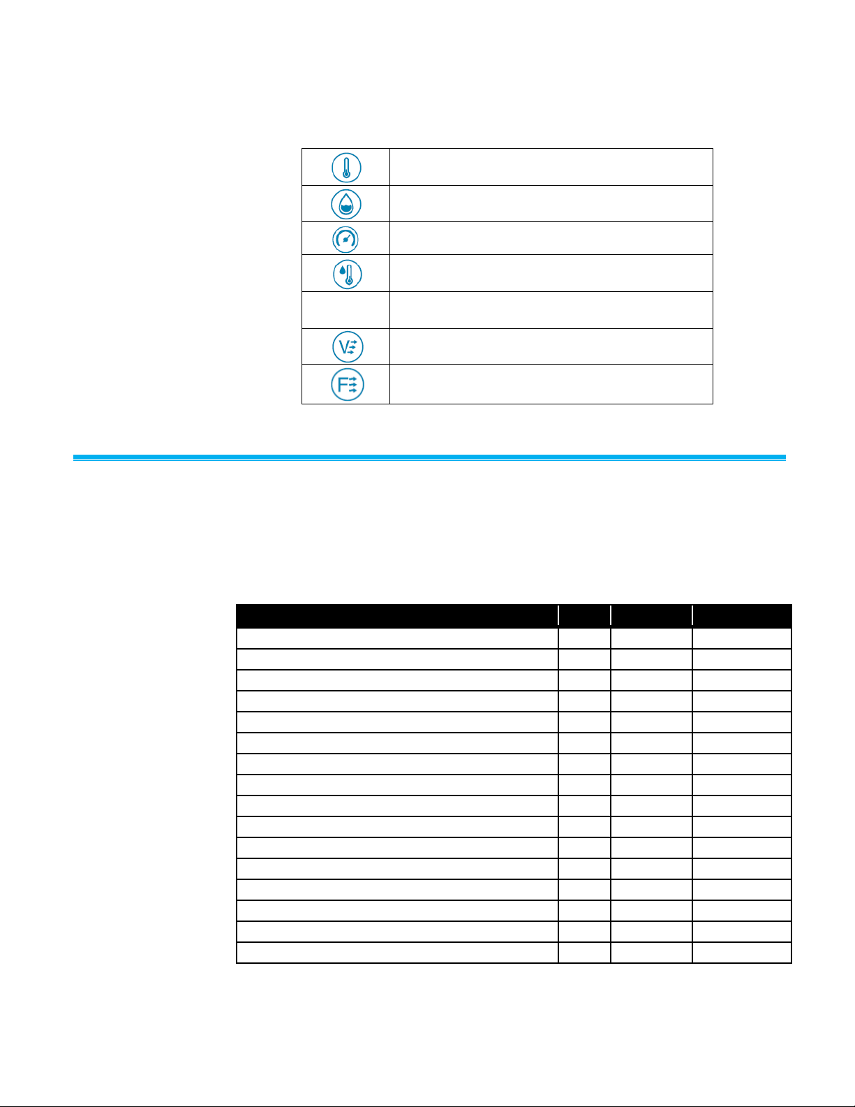
Common Symbols
The following symbols are used in this manual and on the product. The
following is a brief explanation of the meanings of these common symbols.
AirPro Mobile
The AirPro Mobile application has multiple user levels such as Basic,
Advanced, and Professional. The Basic level is available for free. The
Advanced and Professionals user levels are license based. You can select
the level of features you need for your application according to the
functionality matrix shown below.
Before you can use AirPro Mobile, you must first create a new account or log
into an existing account. Once you have an account, AirPro Mobile enables
the features as defined by the account’s license level.
14 AirPro® Instrument Models AP500/AP800
Find Quality Products Online at: sales@GlobalTestSupply.com
www.GlobalTestSupply.com
Page 21

To log in:
1. Tap the AirPro Mobile icon
on the screen of your
smartphone.
2. When the Login screen appears,
enter the email address and
password that you have
registered and select Login.
Note: See Create an Account
information on registering your email
address.
Connect AirPro Mobile with Probe
1. After you log in, AirPro Mobile
looks for available probes. If “No
probes connected” is displayed,
power on an AirPro instrument
such as the Model AP800 or
Model AP500 with an attached
probe.
2. Select Connect.
Log in to AirPro Mobile
Find Quality Products Online at: sales@GlobalTestSupply.com
16 AirPro® Instrument Models AP500/AP800
www.GlobalTestSupply.com
Page 22

Available Probes
AirPro Mobile lists the probe(s) that
have been found. For each probe
found, it displays the probe model,
the probe serial number, and the
programmable Unit Name. If you do
not see your probe, swipe the
Available Probes screen to refresh it.
1. Select Connect. When AirPro
Mobile connects to the probe, it
will show Disconnect and the
probe will show a solid blue LED.
2. Select Done to display the Probe
Measurement screen for each
connected probe.
With an Advanced license you can
connect up to two probes and with
Professional licenses you can
connect up to six probes.
Probe Specific Configurations
Set up the Probe
Many of the settings on the Probe
Measurement screen and the
instrument interface can be
configured from the Probe Settings
menu.
To configure these settings tap the
icon on the Probe
Measurement screen.
Find Quality Products Online at: sales@GlobalTestSupply.com
Chapter 3: Operation 17
www.GlobalTestSupply.com
Page 23

Show a Target Value
A target dial can be configured for
the primary measurement. This will
show you how far off the current
reading is from a desired value.
To set and display a target value
from the Probe Measurement
display:
1. Tap .
2. Enable Show a Target Value.
3. Enter a Target Value and select
Save.
4. Enter a Target Range and select
Save.
Your selection is saved to
AirPro Mobile.
Data Logging
Data Logging is available with Advanced and Professional licenses. You can
log data with multiple probes simultaneously to develop an assessment of
system-wide performance. You can log in one of two modes, either Manual
Save mode or Continuous Save mode. With Manual Save you can decide
when you want to collect a sample. Alternatively with Continuous Save you
can automate data collection. By default AirPro Mobile saves data to your
smartphone. This requires you to keep your smartphone within 80 ft. (25 m) in
line of sight of your probe. With the Professional user license you have the
additional option of unattended logging. Unattended logging lets you save
measurement data to the instruments SD card (not available from TSI) so that
you can disconnect your smartphone and take it with you. When logging to
the probe’s memory card the instrument will automatically disconnect from
AirPro Mobile, the display will indicate it is logging data and it will not
connect to any AirPro Mobile application until the test length completes.
Data can be viewed with AirPro Mobile or the associated file(s) can be moved
to your desktop computer and opened with spreadsheet applications such as
Microsoft® Excel® spreadsheet program.
Find Quality Products Online at: sales@GlobalTestSupply.com
18 AirPro® Instrument Models AP500/AP800
www.GlobalTestSupply.com
Page 24

Logging
Logging can be managed while you
monitor measurements from the
Logging screen.
1. Connect at least one probe to
AirPro Mobile.
2. Tap the icon to enter the
Logging screen. The Logging
screen displays whether you are
in Manual Save mode or
Continuous Save mode. Data
logged will vary depending on the
mode.
Start Logging
Every time you initiate a log, data will
be collected simultaneously from all
connected probes.
1. Prior to starting the log, you can
identify the test details by
attaching photos and comments
.
2. Tap to start the data
collection. Alternatively you can
start it by pressing from your
probe keypad.
3. AirPro Mobile will indicate when
data collection is complete.
4. See Data Files for instructions on
viewing and managing the logged
data.
Find Quality Products Online at: sales@GlobalTestSupply.com
Chapter 3: Operation 19
www.GlobalTestSupply.com
Page 25

Data Logging Settings
Set Up Logging
Parameters for Data Logging can be
accessed from the Log Settings
menu. These settings are saved to
AirPro Mobile.
1. Tap to configure or view the
logging parameters.
2. Select Test ID to change the
name of the test file. If you do not
enter a Test ID, AirPro Mobile will
assign a name.
3. To change the logging mode,
Select Manual Save or
Continuous Save.
Data Files
The Data File menu provides a list of the test records that you created from
the Data Logging screen. It is available with Advanced and Professional
AirPro Mobile user licenses. You can view logged information from AirPro
Mobile. You can also manage the data files from this screen. For instance you
can delete files, add photos, or distribute files to your desktop system for
further reporting.
20 AirPro® Instrument Models AP500/AP800
Find Quality Products Online at: sales@GlobalTestSupply.com
www.GlobalTestSupply.com
Page 26

Data Files
The Data Files screen lists the files
stored with AirPro Mobile.
Tap to access the data files
menu.
Select any test id to view its
details.
View Data File Information
For each data file, you can view and
change information that you
previously associated with the test
such as the Test Name, Comments
and Attachments.
Summary statistics are shown in the
Probe Stats table.
Select Samples to display the
sample records associated with
the test.
Select Graph to select the
measurements you would like to
see graphed. (Available with
Professional user license.)
You can clear all the samples from
the test. After the data is cleared, the
Test ID will become available again
for taking new data.
Find Quality Products Online at: sales@GlobalTestSupply.com
Chapter 3: Operation 21
www.GlobalTestSupply.com
Page 27

Delete Data Files
To delete test files in AirPro Mobile for
iOS, tap Select, mark those tests you
want to delete and tap . Then
select Done.
With AirPro Mobile for Android, tap
and hold any test name in the list. A
Select Test menu will appear.
Mark the files you want to delete and
then select and select Delete.
Share Data Files
To share the information of one or
more tests with someone, tap Select
and mark those tests you want to
share. Select the icon and then
select the appropriate application to
complete the operation.
With AirPro Mobile for Android, tap
and hold any test name in the list. A
Select Test menu will appear.
Mark the files you want to share.
Select the icon and then select
the appropriate application to
complete the operation.
Find Quality Products Online at: sales@GlobalTestSupply.com
22 AirPro® Instrument Models AP500/AP800
www.GlobalTestSupply.com
Page 28

Create a New Test
To manually create a new test record,
select . By default, the current
data file name (for example Test ID)
will be incremented by one. You can
also change the name by adding text,
numbers, and punctuation for the new
test file name.
Select Save when done.
This test record is made available for
logging samples. See Data Logging
for more information.
Workflows
Conducting Workflow
To begin the Workflow, tap the
workflow icon .
The Duct Traverse Workflow is available with the Professional AirPro Mobile
user license. There are two Duct Traverse Methods that are available:
log-Tchebycheff (or simply log-T) and Equal Area.
The Workflow feature will step you through the measurement. AirPro Mobile
assists you in calculating and logging the measurement points.
Find Quality Products Online at: sales@GlobalTestSupply.com
Chapter 3: Operation 23
www.GlobalTestSupply.com
Page 29

Select Duct Type
Select the type of duct traverse you
will be performing with the probe:
rectangular or circular.
A rectangular duct traverse is
selected in this example. The steps of
a circular traverse are similar.
Duct Traverse Setup
Enter the duct’s outer dimensions
and wall thickness. If you know
the internal dimensions of the
duct, enter those but specify a
wall thickness of 0.
Note: The dimensions you specify
here will be retained in the
probe after you complete the
Duct Traverse Workflow. These
will become the new
dimensions used in flow
calculation. For more
information see the Flow
calculation setup or Pitot Flow
Setup in the Probe Settings
menu.
Select the type of traverse that
you want to do, Log-T or
Equal Area.
AirPro Mobile calculates the insertion
depths from the information that you
entered.
Find Quality Products Online at: sales@GlobalTestSupply.com
24 AirPro® Instrument Models AP500/AP800
www.GlobalTestSupply.com
Page 30

Duct Traverse Setup (continued)
Select Next to view the settings for
the probe and for the data logging.
Duct Traverse Setup (continued)
Parameters for data logging are
shown.
Specify a Duct Traverse name;
all data will be logged under this
Test ID.
With the Sampling Interval
specify how long to capture data
at each insertion point.
Duct traverses must be done in
Manual logging mode. Select
View before saving if you want a
choice to discard or save each
sample.
Note: The values you specify here
are not retained after you have
completed the Duct Traverse
workflow.
Find Quality Products Online at: sales@GlobalTestSupply.com
Chapter 3: Operation 25
www.GlobalTestSupply.com
Page 31

Duct Traverse Setup (continued)
You can select any probe connected
to AirPro Mobile capable of
performing a duct traverse: VTH-S,
VTH-A, VT-S, VT-A, AP800.
Verify the probe corresponds to
the one you wish and if it does
not, click on Select a New Probe.
Also, select the Probe
orientation into the duct: Vertical
or Horizontal.
Duct Traverse Setup (continued)
Applicable parameters from the Probe
Settings menu are shown.
Note: The values you specify here will
be retained in the probe after
you exit the Duct Traverse
Workflow.
Select the Primary
Measurement which specifies the
measurement you want to monitor
during the duct traverse: flow or
velocity. This does not affect
which measurements are logged.
Verify the settings are correct for
the measurement corrections
and offsets.
Verify the probe has a sufficient
Battery level to complete the
workflow.
Select Next to view the Traverse
Screen.
Find Quality Products Online at: sales@GlobalTestSupply.com
26 AirPro® Instrument Models AP500/AP800
www.GlobalTestSupply.com
Page 32

Duct Traverse Setup (continued)
Insert the probe in the first access
port and tap to take a data sample.
Alternatively you can start sampling
by pressing from your probe
keypad.
After the data sample completes, the
location indicator advances to the
next insertion point. You can use the
and arrows to skip insertion
points. You can also tap on any point
to take a sample.
All readings are saved in the duct
traverse file. The file can be viewed
from the Data Files menu.
Select Done when the traverse is
completed.
Global Setup, Units of Measure and
Standard/Actual Setup
Units of Measure
Multiple units of measure are
available from the global setup menu.
The settings you apply will be
reflected in AirPro Mobile, all data
logs and the probe display. They will
affect all connected probes.
With AirPro Mobile for iOS, select
and then select Units of
Measure from the menu.
Alternatively with AirPro Mobile
for Android, select , and then
select Preferences, and then
Units of Measure.
Select the measurement you want
to change.
Select the new units of measure
you want to use and <.
The settings are saved to the probe.
The Global setup menus let you configure and view global information for
AirPro Mobile and all attached probes. The Global parameters include your
user account and profile information and your user preferences such as Units
of Measure and Standard/Actual setup.
Find Quality Products Online at: sales@GlobalTestSupply.com
Chapter 3: Operation 27
www.GlobalTestSupply.com
Page 33

Standard/Actual Setup
Standard or actual corrections can be
applied to flows and velocities. The
settings you apply will be reflected in
AirPro Mobile, the probe display and
data logs. They will affect all
connected probes.
With AirPro Mobile for iOS, select
, and then select
Standard/Actual setup from the
menu. Alternatively with AirPro
Mobile for Android, select ,
and then select Preferences, and
then Actual/Standard setup.
For the Model AP800, enter the
temperature value you want to
use for calculations of Standard
and Actual pitot velocity and flow.
The AP500 and AP800 measure
the actual barometric pressure
using an internal sensor; no user
entry is needed.
The settings are saved to the probe.
User Profile
From the Global setup menu you can
view or change your user profile
including, license type, name, email
address, role, business name and
phone number. You can also change
your password.
With AirPro Mobile for iOS, select
, and then select User Profile
from the menu. Alternatively with
AirPro Mobile for Android, select
, and then select User Profile.
To change any field, select Edit.
Select Save.
Select < to return to the previous
screen.
Note: With AirPro Mobile for iOS, the
option to change password is
shown in the scroll list only
once you have selected Edit.
Find Quality Products Online at: sales@GlobalTestSupply.com
28 AirPro® Instrument Models AP500/AP800
www.GlobalTestSupply.com
Page 34

Saved Sample Notification
Set sound and/or vibration notification
when manually saving samples.
With AirPro Mobile for iOS, select
. Alternatively with AirPro
Mobile for Android, select and
then select Preferences.
Select Saved Sample
Notification from the menu.
Select Sound or Vibration to
enable/disable the action for
sample notification.
Select < to return to the previous
screen.
Find Quality Products Online at: sales@GlobalTestSupply.com
Chapter 3: Operation 29
www.GlobalTestSupply.com
Page 35

Symptom
Possible Causes
Corrective Action
Unit does not turn on.
Low or dead batteries.
Replace batteries or plug in AC adapter.
Dirty battery contacts.
Clean the battery contacts.
Velocity reading fluctuates
unstable.
Fluctuating flow.
Reposition probe in less turbulent flow or
use longer time constant.
Improper use of extensions.
Do not connect more than 3 extensions to
the probe.
“No probe” displayed on
instrument.
Probe is not attached or a sufficient
connection is not made.
Securely tighten the probe down. Power
cycle.
Probe or handle is damaged.
Return both to TSI for service.
“Service Handle” displayed
on instrument.
Handle is damaged.
Return handle for service.
“Service Probe” displayed
on instrument.
Probe is damaged.
Return probe for service.
“Over heat” displayed on
instrument.
Battery is damaged.
Handle is being used outside of
temperature range.
Replace battery.
Remove from external heat source.
“Low Battery” displayed on
instrument.
Battery power is low.
Charge battery.
Instrument shuts off quickly.
AirPro Mobile Auto shutoff or Auto
sleep is turned on.
Configure probe settings from AirPro
Mobile.
Instrument is overheated. See Spec.
Replace battery or remove from external
heat source.
Battery is low.
Charge battery. If battery is charged, then
replace it.
Probe is disconnected.
Reconnect probe.
NOT able to charge battery
in Handle. Charging LED
will not light.
AC/DC Adapter defective.
Replace AC/DC Adapter with new.
Incorrect AC/DC Adapter used.
Only use TSI PN 800531.
USB-micro connector on Handle
loose or broken.
Re-insert AC/DC Adapter cable into handle
and ensure correct fit. If still NOT working,
return Handle for service.
Handle powers down
automatically with charged
battery installed.
Battery installed with incorrect
polarity.
Remove battery and re-install observing
correct polarity.
C H A P T E R 5
Troubleshooting
The table below lists the symptoms, possible causes, and recommended
solutions for common problems encountered with the instrument or AirPro
Mobile. If your symptom is not listed, or if none of the solutions solves your
problem, please contact TSI.
Find Quality Products Online at: sales@GlobalTestSupply.com
www.GlobalTestSupply.com
33
Page 36

Symptom
Possible Causes
Corrective Action
“---“ is displayed on handle.
Invalid measurement has been
detected.
If this happens frequently then return probe
for service.
9e20 is displayed in the log
or in AirPro Mobile.
AirPro Mobile shows “You
have reached your 2 device
limit for this account.”
Each time you download AirPro
Mobile to your Smartphone, it is
considered a new association. You
are only allowed two association
licenses.
Red Exclamation mark
appears on the SD card
indicator.
Corrupt data file or card has less than
100 MB free space.
Replace card or delete files on card to free
more space.
Charging LED flashes.
Battery has an error condition.
Verify battery is oriented correctly.
Replace battery.
W A R N I N G
Remove the probe from excessive temperature immediately: excessive heat
can damage the sensor. Operating temperature limits can be found in
Appendix A, Specifications. The pressure sensor is protected from damage
up to 7 psi (48 kPA or 360 mmHg). At higher pressure it can burst.
Find Quality Products Online at: sales@GlobalTestSupply.com
34 AirPro® Instrument Models AP500/AP800
www.GlobalTestSupply.com
Page 37

A P P E N D I X A
Specifications
Specifications are subject to change without notice.
Model AP500 AirPro Mobile with Probes
Wireless Connectivity Range (line of sight)
80 ft. (25 m) maximum
Model AP500
Barometric Pressure
Range ............................. 20.36 to 36.65 in. Hg (517.1 to 930.9 mm Hg)
Accuracy ......................... ±2% of reading
Instrument Temperature Range
Operating (Electronics) .. 40 to 113°F (5 to 45°C)
Storage .......................... -4 to 140°F (-20 to 60°C)
Display Interface
Organic light-emitting diode (OLED)
0.4 in. (10 mm) digit height
External Meter Dimensions
2.1 in. x 8.5 in. x 1.6 in. (53 mm x 181 mm x 40 mm)
Meter Weight with Batteries
0.5 lbs. (0.23 kg)
Power Requirements
AirPro Li-ion battery ....... 3500 mAh
AC Adapter ..................... (TSI part number 800531 only)
Input ................................ 90 to 240 VAC, 50 to 60 Hz
Output ............................. 5 VDC, 2A
Battery Life
8+ hours at 100 ft/min (0.5 m/s) and 77°F (25°C)
35
Find Quality Products Online at: sales@GlobalTestSupply.com
www.GlobalTestSupply.com
Page 38

Model AP500 AirPro Measu r e m e n t Probes
Velocity (VT-S, VT-A, VTH-S, VTH-A)
Range .............................. 0 to 6,000 ft/min (0 to 30 m/s)
Accuracy
Resolution ....................... 1 ft/min (0.01 m/s)
Temperature (VT-S, VT-A, VTH-S, VTH-A, TH-S)
Range .............................. 14 to 150°F (-10 to 65°C)
Accuracy3 ........................ ±0.5°F (±0.3°C)
Resolution ....................... 0.1°F (0.1°C)
Relative Humidity (VTH-S, VTH-A, TH-S)
Range .............................. 5 to 95% RH
Accuracy4 ........................ ±3% RH
Range .............................. 0.1% RH
1&2
..................... ±3% of reading or ±3 ft/min (±0.015 m/s),
whichever is greater
Straight Probe Dimensions (VT-S, VTH-S, TH-S)
Probe length .................... 12 in. (305 mm)
Probe diameter (largest) . 0.375 in. (9.5 mm)
Articulating Probe Dimensions (VT-A, VTH-A)
Probe length .................... 12 in. (305 mm)
Probe diameter (largest) . 0.375 in. (9.5 mm)
Articulating section length 6.0 in (15.24 cm)
Probe Extension Dimensions (800529)
Probe length .................... 12 in. (305 mm)
Probe diameter (largest) . 0.375 in. (9.5 mm)
1
Temperature compensated over an air temperature range of 40 to 150°F (5 to 65°C).
2
The accuracy statement begins at 30 ft/min through 6,000 ft/min (0.15 m/s through 30 m/s).
3
Accuracy with instrument case at 77°F (25°C), add uncertainty of 0.05°F/°F (0.03°C/°C) for
change in instrument temperature.
4
Accuracy with probe at 77°F (25°C). Add uncertainty of 0.1% RH/°F (0.2% RH/°C) for change in
probe temperature. Includes 1% hysteresis.
36 AirPro® Instrument Models AP500/AP800
Find Quality Products Online at: sales@GlobalTestSupply.com
www.GlobalTestSupply.com
Page 39

Model AP800
Wireless Connectivity Range (line of sight)
80 ft. (25 m) maximum
Static / Differential Pressure
Range1 ............................ -15 to +15 in. H2O
(-28.0 to +28.0 mm Hg, -3735 to +3735 Pa)
Accuracy ......................... ±1% of reading ±0.005 in. H2O
(±0.01 mm Hg, ±1 Pa)
Resolution ....................... 0.001 in. H2O (0.1 Pa, 0.01 mm Hg)
Velocity (Pitot Probe)
Range2 ............................ 250 to 15,500 ft/min (1.27 to 78.7 m/s)
Accuracy3: ....................... ±1.5% at 2000 ft/min (10.16 m/s)
Resolution ....................... 1 ft/min (0.1 m/s)
Barometric Pressure
Range ............................. 20.36 to 36.65 in. Hg (517.1 to 930.9 mm Hg)
Accuracy ......................... ±2% of reading
Instrument Temperature Range
Operating ........................ 40 to 113°F (5 to 45°C)
Storage ........................... -4 to 140°F (-20 to 60°C)
Display Interface
Organic light-emitting diode (OLED)
0.4 in. (10 mm) digit height
External Meter Dimensions
2.1 in. x 7.1 in. x 1.6 in. (53 mm x 181 mm x 40 mm)
Meter Weight
Weight with batteries: 0.45 lbs (0.20 kg)
Power Requirements
AirPro Li-ion battery ....... 3500 mAh
AC Adapter ..................... (TSI part number 800531 only)
Input ................................ 90 to 240 VAC, 50 to 60 Hz
Output ............................. 5 VDC, 2A
Battery Life
32+ hours
1
Overpressure range = 7 psi (190 in. H2O, 360 mmHg, 48 kPa).
2
Pressure velocity measurements are not recommended below 1,000 ft/min (5 m/s).
3
Accuracy is a function of converting pressure to velocity. Conversion accuracy improves when
actual pressure values increase.
Appendix A: Specifications 37
Find Quality Products Online at: sales@GlobalTestSupply.com
www.GlobalTestSupply.com
 Loading...