

Page 1

VelociCalc®/
VelociCalc® Pro
Air Velocity Meter
Model 9600 Series
Operation and Service Manual
P/N 6016122, Revision C
August 2022
Find Quality Products Online at: sales@GlobalTestSupply.com
www.GlobalTestSupply.com
Page 2

Start Seeing the Benefits
of Registering Today!
Thank you for your TSI® instrument purchase. Occasionally, TSI®
releases information on software updates, product enhancements and
new products. By registering your instrument, TSI® will be able to send
this important information to you.
As part of the registration process, you will be asked for your comments
on TSI products and services. TSI’s customer feedback program gives
customers like you a way to tell us how we are doing.
ii VelociCalc®/VeloCalc® Pro Air Velocity Meter 9600 Series
Find Quality Products Online at: sales@GlobalTestSupply.com
www.GlobalTestSupply.com
Page 3

Copyright
Address
Fax No.
E-mail Address
Limitation of Warranty
and Liability
(effective February 2015)
Warranty
Seller warrants the goods, excluding software, sold hereunder, under normal use
and service as described in the operator's manual, to be free from defects in
workmanship and material for 24 months, or if less, the length of time specified
in the operator's manual, from the date of shipment to the customer. This
warranty period is inclusive of any statutory warranty. This limited warranty is
subject to the following exclusions and exceptions:
a. Hot-wire or hot-film sensors used with research anemometers, and certain other
components when indicated in specifications, are warranted for 90 days from the
date of shipment;
b. Carbon monoxide (CO) Electro-chemical sensors are warranted for 12 months
from the date of shipment.
c. Pumps are warranted for hours of operation as set forth in product or
operator’s manuals;
d. Parts repaired or replaced as a result of repair services are warranted to be free
from defects in workmanship and material, under normal use, for 90 days from the
date of shipment;
e. Seller does not provide any warranty on finished goods manufactured by others or
on any fuses, batteries or other consumable materials. Only the original
manufacturer's warranty applies;
f. This warranty does not cover calibration requirements, and seller warrants
only that the instrument or product is properly calibrated at the time of its
manufacture. Instruments returned for calibration are not covered by
this warranty;
g. This warranty is VOID if the instrument is opened by anyone other than a
factory authorized service center with the one exception where
requirements set forth in the manual allow an operator to replace
consumables or perform recommended cleaning;
h. This warranty is VOID if the product has been misused, neglected, subjected
to accidental or intentional damage, or is not properly installed, maintained, or
cleaned according to the requirements of the manual. Unless specifically
authorized in a separate writing by Seller, Seller makes no warranty with
respect to, and shall have no liability in connection with, goods which are
incorporated into other products or equipment, or which are modified by any
person other than Seller.
The foregoing is IN LIEU OF all other warranties and is subject to the
LIMITATIONS stated herein. NO OTHER EXPRESS OR IMPLIED WARRANTY
OF FITNESS FOR PARTICULAR PURPOSE OR MERCHANTABILITY IS MADE.
WITH RESPECT TO SELLER’S BREACH OF THE IMPLIED WARRANTY
AGAINST INFRINGEMENT, SAID WARRANTY IS LIMITED TO CLAIMS OF
DIRECT INFRINGEMENT AND EXCLUDES CLAIMS OF CONTRIBUTORY OR
INDUCED INFRINGEMENTS. BUYER’S EXCLUSIVE REMEDY SHALL BE THE
RETURN OF THE PURCHASE PRICE DISCOUNTED FOR REASONABLE
WEAR AND TEAR OR AT SELLER’S OPTION REPLACEMENT OF THE
GOODS WITH NON-INFRINGING GOODS.
iii
Find Quality Products Online at: sales@GlobalTestSupply.com
www.GlobalTestSupply.com
Page 4

Service Policy
Trademarks
TO THE EXTENT PERMITTED BY LAW, THE EXCLUSIVE REMEDY OF THE
USER OR BUYER, AND THE LIMIT OF SELLER'S LIABILITY FOR ANY AND
ALL LOSSES, INJURIES, OR DAMAGES CONCERNING THE GOODS
(INCLUDING CLAIMS BASED ON CONTRACT, NEGLIGENCE, TORT, STRICT
LIABILITY OR OTHERWISE) SHALL BE THE RETURN OF GOODS TO SELLER
AND THE REFUND OF THE PURCHASE PRICE, OR, AT THE OPTION OF
SELLER, THE REPAIR OR REPLACEMENT OF THE GOODS. IN THE CASE OF
SOFTWARE, SELLER WILL REPAIR OR REPLACE DEFECTIVE SOFTWARE
OR IF UNABLE TO DO SO, WILL REFUND THE PURCHASE PRICE OF THE
SOFTWARE. IN NO EVENT SHALL SELLER BE LIABLE FOR LOST PROFITS,
BUSINESS INTERRUPTION, OR ANY SPECIAL, INDIRECT, CONSEQUENTIAL
OR INCIDENTAL DAMAGES. SELLER SHALL NOT BE RESPONSIBLE FOR
INSTALLATION, DISMANTLING OR REINSTALLATION COSTS OR CHARGES.
No Action, regardless of form, may be brought against Seller more than 12
months after a cause of action has accrued. The goods returned under warranty
to Seller's factory shall be at Buyer's risk of loss, and will be returned, if at all, at
Seller's risk of loss.
Buyer and all users are deemed to have accepted this LIMITATION OF
WARRANTY AND LIABILITY, which contains the complete and exclusive limited
warranty of Seller. This LIMITATION OF WARRANTY AND LIABILITY may not
be amended, modified or its terms waived, except by writing signed by an Officer
of Seller.
Knowing that inoperative or defective instruments are as detrimental to TSI as
they are to our customers, our service policy is designed to give prompt attention
to any problems. If any malfunction is discovered, please contact your nearest
sales office or representative, or call Customer Service department
TSI, TSI logo, VelociCalc and VelociCalc Pro are registered trademarks of TSI
Incorporated in the United States and may be protected under other country’s
trademark registrations. Wi-Fi is a registered trademark of the Wi-Fi Alliance.
Find Quality Products Online at: sales@GlobalTestSupply.com
iv VelociCalc®/VeloCalc® Pro Air Velocity Meter 9600 Series
www.GlobalTestSupply.com
Page 5

Contents
WARRANTY ....................................................................................... III
SAFETY ............................................................................................ VII
Description of Caution/Warning Symbols ....................................... vii
Caution ......................................................................................... vii
Warning ........................................................................................ vii
Caution and Warning Symbols ...................................................... viii
Labels ............................................................................................. viii
RoHS ................................................................................................ ix
CE .................................................................................................... ix
Reusing and Recycling .................................................................... ix
Bluetooth® Safety and Compliance(9650) ....................................... ix
CHAPTER 1 UNPACKING AND PARTS IDENTIFICATION ............. 1
Standard Equipment ......................................................................... 1
Optional Plug In Probes .................................................................... 2
Optional Accessories and Replacement Parts ................................. 3
CHAPTER 2 SETTING UP THE VELOCICALC® METER ................. 5
Providing Power to the VelociCalc® Meter ........................................ 5
Installing the Batteries ................................................................... 5
Using the AC/DC Power Supply .................................................... 5
Case Magnets, Probe Holder and Wrist Strap .................................. 6
Connecting Ventilation or IAQ Probes .............................................. 6
Extending the Probe ...................................................................... 7
Retracting the Probe ...................................................................... 7
Differential Pressure Capable Models (9630, 9650 and 9650-NB) .. 7
Connecting the Static Pressure Probe .......................................... 8
Connecting an Optional Pitot Probe .............................................. 8
Thermocouple Port ............................................................................ 9
Connecting the Thermocouples ..................................................... 9
Connecting the Optional Bluetooth Portable Printer Device
(Model 9650 only) ........................................................................ 10
Connecting to a Computer .............................................................. 11
CHAPTER 3 OPERATIONAL OVERVIEW ...................................... 13
Keypad Button Names .................................................................... 13
Icons ................................................................................................ 13
Measurement Icons ..................................................................... 13
Dashboard Icons .......................................................................... 14
Soft Key Icons .............................................................................. 15
Programmable Soft Key Icons ..................................................... 15
Definitions ....................................................................................... 16
Language Selection ........................................................................ 17
Dashboard ....................................................................................... 17
Dashboard ................................................................................... 17
Assign Programmable Soft Keys .................................................... 18
Main Menu ...................................................................................... 19
v
Find Quality Products Online at: sales@GlobalTestSupply.com
www.GlobalTestSupply.com
Page 6

Zero Pressure ................................................................................. 19
Settings........................................................................................... 20
Flow Setup ..................................................................................... 20
Workflows ....................................................................................... 21
Logging Profile ............................................................................... 21
Manage Data .................................................................................. 22
CHAPTER 4 SETTINGS .................................................................. 23
Display Order ................................................................................. 23
Actual/Standard .............................................................................. 24
Calibration ...................................................................................... 24
General Settings ............................................................................. 26
Unit Settings ................................................................................... 27
Date and Time ................................................................................ 27
Display/Power ................................................................................ 28
Device Information ......................................................................... 28
CHAPTER 5 LOGGING PROFILE AND CUSTOM
TESTID LABELS .............................................................................. 29
Manual Mode Logging .................................................................... 29
Continuous Mode Logging ............................................................. 30
Customize TESTID Labels in Meter ............................................... 30
Customize TESTID Labels using TestID.csv ................................. 31
CHAPTER 6 MANAGE DATA ......................................................... 33
Viewing a Log File (TESTID) .......................................................... 33
Viewing Samples ............................................................................ 34
Delete Log Files ............................................................................. 34
Opening Log CSV Files on a PC .................................................... 34
CHAPTER 7 WORKFLOWS ............................................................ 35
Percent Outside Air (%OA) Calculation Procedure ........................ 35
Heat Flow Procedure ...................................................................... 36
Duct Traverse Procedure (9650, 9650-NB) ................................... 37
CHAPTER 8 MAINTENANCE ......................................................... 41
Cleaning/Disinfecting ...................................................................... 41
Bi-Annual Maintenance Checks ..................................................... 42
CHAPTER 9 TROUBLESHOOTING ............................................... 43
CHAPTER 10 HELP ........................................................................ 45
TSI® Technical Support/Service ..................................................... 45
APPENDIX A SPECIFICATIONS .................................................... 47
vi VelociCalc®/VeloCalc® Pro Air Velocity Meter 9600 Series
Find Quality Products Online at: sales@GlobalTestSupply.com
www.GlobalTestSupply.com
Page 7

W AR NI NG S
• The instrument must be used in the manner described in this
manual. Failure to follow all of the procedures described in this
manual can result in serious injury to you or can cause
irrevocable damage to the instrument.
• There are no user-serviceable parts inside the instrument. Refer
all repairs to a qualified factory-authorized technician.
• The VelociCalc® meter is not rated for intrinsic safety. DO NOT
operate the VelociCalc® meter under conditions where there is a
risk of fire or explosion.
C A U TI ON
CAUTION means that failure to follow the procedures prescribed in
this manual might result in irreparable equipment damage.
Important information about the operation and maintenance of this
instrument is included in this manual.
W AR NI NG
WARNING means that unsafe use of the instrument could result in
serious injury to you or cause damage to the instrument. Follow the
procedures prescribed.
Safety
This section provides instructions to ensure safe and proper operation
of the VelociCalc® Air Velocity Meter Series 9600.
Description o f C a u t i o n / W a r n i n g S y m b o l s
Appropriate caution/warning statements are used throughout the
manual and on the instrument that require you to take cautionary
measures when working with the instrument.
Caution
Warning
Find Quality Products Online at: sales@GlobalTestSupply.com
vii
www.GlobalTestSupply.com
Page 8
Warns that uninsulated voltage within the instrument
may have sufficient magnitude to cause electric shock.
Therefore, it is dangerous to make contact with any
part inside the instrument.
Warns that the instrument contains a laser and that
important information about its safe operation and
maintenance is included in the manual.
Warns that the instrument is susceptible to electrostatic discharge (ESD) and ESD protection should be
followed to avoid damage.
Indicates the connector is connected to earth ground
and cabinet ground.
1. Example
2. Example
3. Example
4. Example
5. Example
6. Example
Caution an d W a r n i n g S y m b o l s
The following symbols may accompany cautions and warnings to
indicate the nature and consequences of hazards:
Labels
Advisory and identification labels or markings are attached to
the instrument.
Find Quality Products Online at: sales@GlobalTestSupply.com
viii VelociCalc®/VeloCalc® Pro Air Velocity Meter 9600 Series
www.GlobalTestSupply.com
Page 9

7. Example
8. Example
9. European symbol for nondisposable item. Item must
be recycled.
RoHS
VelociCalc® 9600 Series instruments are RoHS compliant.
CE
VelociCalc® 9600 Series instruments are CE compliant.
Reusing an d Re c y c l i n g
As part of TSI® Incorporated’s effort to have a minimal negative
impact on the communities in which its products are manufactured
and used:
DO NOT dispose of batteries in the trash. Follow local
environmental requirements for battery recycling.
If instrument becomes obsolete, return to TSI® for disassembly
and recycling.
Bluetooth® Safety a n d C o m p l i a n c e ( 9 6 5 0 )
This product uses Bluetooth® v4.2 to communicate with
software applications.
Hereby, TSI® Incorporated declares that this Bluetooth® test and
measurement instrument is in compliance with Directive 2014/53/EC.
Transmit Power Rating is +9 dBm, MAX @ 2.4 – 2.5 GHz.
Operation and Service Manual ix
Find Quality Products Online at: sales@GlobalTestSupply.com
www.GlobalTestSupply.com
Page 10

NOT ICE
This device may not cause interference; this device must accept
any interference, including interference that may cause undesired
operation of the device.
l’appareil ne doit pas produire de brouillage; l’appareil doit
accepter tout brouillage radioélectrique subi, même si le brouillage
est susceptible d’en compromettre le fonctionnement.
NOT ICE
This equipment has been tested and found to comply with the
limits for a Class B digital device, pursuant to part 15 of the FCC
Rules (FCC ID: 2AC7Z-ESP32WROOM32E). These limits are
designed to provide reasonable protection against harmful
interference in a residential installation. This equipment generates,
uses, and can radiate radio frequency energy and, if not installed
and used in accordance with the instructions, may cause harmful
interference to radio communications. However, there is no
guarantee that interference will not occur in a particular
installation. If this equipment does cause harmful interference to
radio or television reception, which can be determined by turning
the equipment off and on, the user is encouraged to try to correct
the interference by one or more of the following measures:
• Reorient or relocate the receiving antenna.
• Increase the separation between the equipment and receiver.
• Connect the equipment into an outlet on a circuit different from
that to which the receiver is connected.
• Consult the dealer or an experienced radio/TV technician
for help.
NOT ICE
This device complies with Industry Canada licence-exempt RSS
standard(s). Operation is subject to the following two conditions:
(1) this device may not cause interference, and (2) this device
must accept any interference, including interference that may
cause undesired operation of the device.
W A R N I N G
Changes or modifications not expressly approved by the party
responsible for compliance could void the user's authority to
operate the equipment.
Find Quality Products Online at: sales@GlobalTestSupply.com
x VelociCalc®/VeloCalc® Pro Air Velocity Meter 9600 Series
www.GlobalTestSupply.com
Page 11

C H A P T E R 1
1. Carrying case
2. Instrument
3. USB cable
4. Static pressure tip (9630,
9650, 9650-NB)
5. Tubing (9630, 9650,
9650-NB)
6. Calibration certificate
7. Manual (English)
Model No.
Description
9600
Multi-Function Ventilation Meter
9630
Multi-Function Ventilation Meter with Differential Pressure
9650-NB
Multi-Function Ventilation Meter with Differential Pressure,
and Workflows
9650
Multi-Function Ventilation Meter with Differential Pressure,
Workflows, and Bluetooth® printing
Unpacking and Parts
Identification
Carefully unpack the instrument and accessories from the shipping
container. Check the individual parts against the list of components
below. If anything is missing or damaged, notify TSI® immediately.
Standard Equi p m e n t
All standard equipment can be purchased separately if needed.
This manual supports the following models:
Find Quality Products Online at: sales@GlobalTestSupply.com
www.GlobalTestSupply.com
1
Page 12
Telescopic Thermoanemometer Probes
Model No.
Description
960
Air Velocity and Temperature, Straight Probe
962
Air Velocity and Temperature, Articulating Probe
964
Air Velocity, Temperature, and Humidity, Straight Probe
966
Air Velocity, Temperature, and Humidity, Articulating Probe
Telescopic Thermohygrometer Probe
Model No.
Description
800220
Air temperature and relative Humidity
Rotating Vane Anemometer Probes
Model No.
Description
995
4 in. (100 mm) Rotating Vane, Air Velocity, and
Temperature
Indoor Air Quality (IAQ) Probes
Model No.
Description
980
Indoor Air Quality Probe, Temperature, Humidity, CO2
982
Indoor Air Quality Probe, Temperature, Humidity, CO2 and
CO K-alloy Thermocouple Probes
Model No.
Description
792
Surface Temperature Probe
794
Air Temperature Probe
Pitot Probes
Part No.
Description
634634000
Pitot Probe 12" (30 cm) - 5/16" (8 mm) diameter
634634001
Pitot Probe 18" (46 cm) - 5/16" (8 mm) diameter
634634002
Pitot Probe 24" (61 cm) - 5/16" (8 mm) diameter
634634003
Pitot Probe 36" (91 cm) - 5/16" (8 mm) diameter
634634005
Pitot Probe 60" (152 cm) - 5/16" (8 mm) diameter
634634004
Telescoping Pitot Probe - 8" to 38" (20 cm to 96 cm)
Optional P l u g I n P r o b e s
2 VelociCalc®/VeloCalc® Pro Air Velocity Meter 9600 Series
Find Quality Products Online at: sales@GlobalTestSupply.com
www.GlobalTestSupply.com
Page 13
Part No.
Description
Picture
800122
AC/DC Adapter/Power Supply
802241
USB Thermal Printer
801190
Bluetooth® Printer (9650 only)
80211
Printer paper (5 rolls)
800681
IAQ probe stand
801748
Telescopic, articulated
extension for 995 RV probe
372000000
8 ft. (2.5 m) tubing
3002017
Static pressure probe
800533
Static Pressure Probes and
Tubing Kit—contains two static
pressure probes and two 4 ft.
(1.2 m) lengths of tubing.
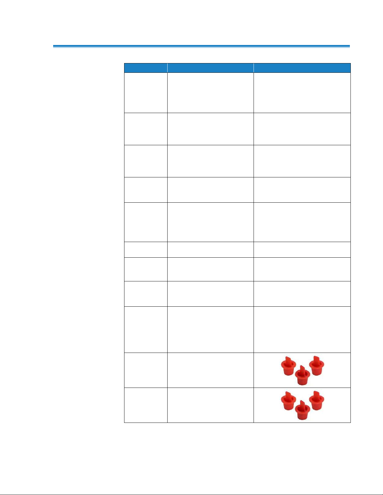
634650002
Duct plugs, 3/8" (9.5 mm)
diameter—1000 pieces
634650003
Duct plugs, 3/8" (9.5 mm)
diameter—5000 pieces
Optional Acces sories and Replacement Parts
Find Quality Products Online at: sales@GlobalTestSupply.com
www.GlobalTestSupply.com
Operation and Service Manual 3
Page 14

Part No.
Description
Picture
800130
Carrying case, small:
Accommodates (1) meter and
up to (2) probes (IAQ or
thermoanemometer)
Find Quality Products Online at: sales@GlobalTestSupply.com
4 VelociCalc®/VeloCalc® Pro Air Velocity Meter 9600 Series
www.GlobalTestSupply.com
Page 15

C A U T I O N
Use only the approved AC/DC power supply (TSI® part number
800122) and DO NOT substitute another adapter or use a computer
to supply power. Use of an incorrect power supply can cause the
measurements to be inaccurate.
AC/DC Power Supply Input
C H A P T E R 2
Setting Up the
VelociCalc® Meter
Providing Powe r t o t h e V e l o c i C a l c® Meter
The Model 9600 Series VelociCalc
powered in one of two ways: four (4) size AA batteries or the optional
AC/DC power supply.
Installing the Batteries
Insert four (4) size AA batteries as indicated by the diagram located
on the inside of the battery compartment.
®
Air Velocity Meter can be
Using the AC/DC Power Supply
The optional AC/DC power supply (800122) can be used to power the
instrument. Be sure to provide the correct voltage and frequency,
which is marked on the back of the AC/DC power supply.
When the AC/DC power supply is connected, the instrument will
automatically turn ON. To turn the instrument off, disconnect the
AC/DC power supply. If batteries are installed, press the power button
for 3 seconds.
Find Quality Products Online at: sales@GlobalTestSupply.com
www.GlobalTestSupply.com
5
Page 16

“D” Shaped
mini-DIN connector
Magnets
Probe Holder
Wrist Strap
Location
Case M a g n e t s , P r o b e H o l d e r a n d Wrist Stra p
The back of the case features built-in magnets that allow for handsfree operation. Two small magnets are near the bottom of the case
and one large magnet in the top next to the serial number label. The
instrument can be affixed to metal components such as sheet metal
ductwork or frames of fume hoods. In addition, the case design
incorporates a probe holder and wrist strap connection.
Connecting Ve n t i l a t i o n o r I A Q P r o b e s
The ventilation and IAQ probes have a “D” shape overmolding on
the mini-DIN connector which must align with the connector at the
base of the 9600 series meter. This will ensure the probe is
properly connected and remains so during use. Once connected
and turned on, refer to the Display Order for displaying the
desired measurements.
6 VelociCalc®/VeloCalc® Pro Air Velocity Meter 9600 Series
Find Quality Products Online at: sales@GlobalTestSupply.com
www.GlobalTestSupply.com
Page 17

N O T ICE
For temperature and humidity measurements, make sure that at
least 3 in. (7.5 cm) of the probe is in the flow to allow the
temperature and humidity sensors to be in the air stream.
W A R N I N G
DO NOT use the instrument or probes near hazardous voltage
sources since serious injury could result.
Negative (-) Pressure Port
Positive (+) Pressure Port
The telescoping probe contains the velocity, temperature, and
humidity sensors. When using the probe, make sure the
sensor window is fully exposed and the orientation dimple is
facing upstream.
Extending the Probe
To extend the probe, hold the handle in one hand while pulling on the
probe tip with the other hand. DO NOT hold the cable while extending
the probe as this prevents the probe from extending.
Retracting the Probe
To retract the probe, hold the handle in one hand while gently pulling
the probe cable until the smallest antenna section is retracted.
Differentia l P r e s s u r e C a p a b l e Models (9630, 9 6 5 0 a n d 9 6 5 0 - NB)
The 9630, 9650, and 9650-NB include pressure ports that can be
used to measure static and differential pressures in ductwork. For
more information, see Application Note TSI-107.
Find Quality Products Online at: sales@GlobalTestSupply.com
www.GlobalTestSupply.com
Operation and Service Manual 7
Page 18

The static pressure probe
included with differential
pressure capable meters is
connected to the “+” port using
the included tubing. The static
pressure probe is used to
measure the duct static
pressure and features a
magnet which holds the probe
to the ductwork.
N O T ICE
The pitot velocity needs a valid temperature to perform the standard
or actual velocity correction. This is accomplished in the
“Actual/Standard Setup” menu. If a thermocouple is plugged in, the
meter will use the temperature reading from the thermocouple. If no
thermocouple is plugged in, the meter will use the setting saved in
the “Actual/Standard Setup” menu.
For more information on entering the temperature manually, refer to
Chapter 4, Actual/Standard Setup section of this manual.
Connecting the Static Pressure Probe
Connecting an Optional Pitot Probe
When connected to a pitot probe, air velocity or air volume can be
measured. A pitot probe can be connected to the “+” and “-” pressure
ports on the pressure capable VelociCalc® meters using two pieces of
tubing of equal length. The total pressure port of the pitot probe
connects to the “+” port on the meter, and the static pressure port of
the pitot probe connects to the “-” port on the meter.
Find Quality Products Online at: sales@GlobalTestSupply.com
8 VelociCalc®/VeloCalc® Pro Air Velocity Meter 9600 Series
www.GlobalTestSupply.com
Page 19
W A R N I N G
DO NOT use the instrument or probes near hazardous voltage
sources since serious injury could result.
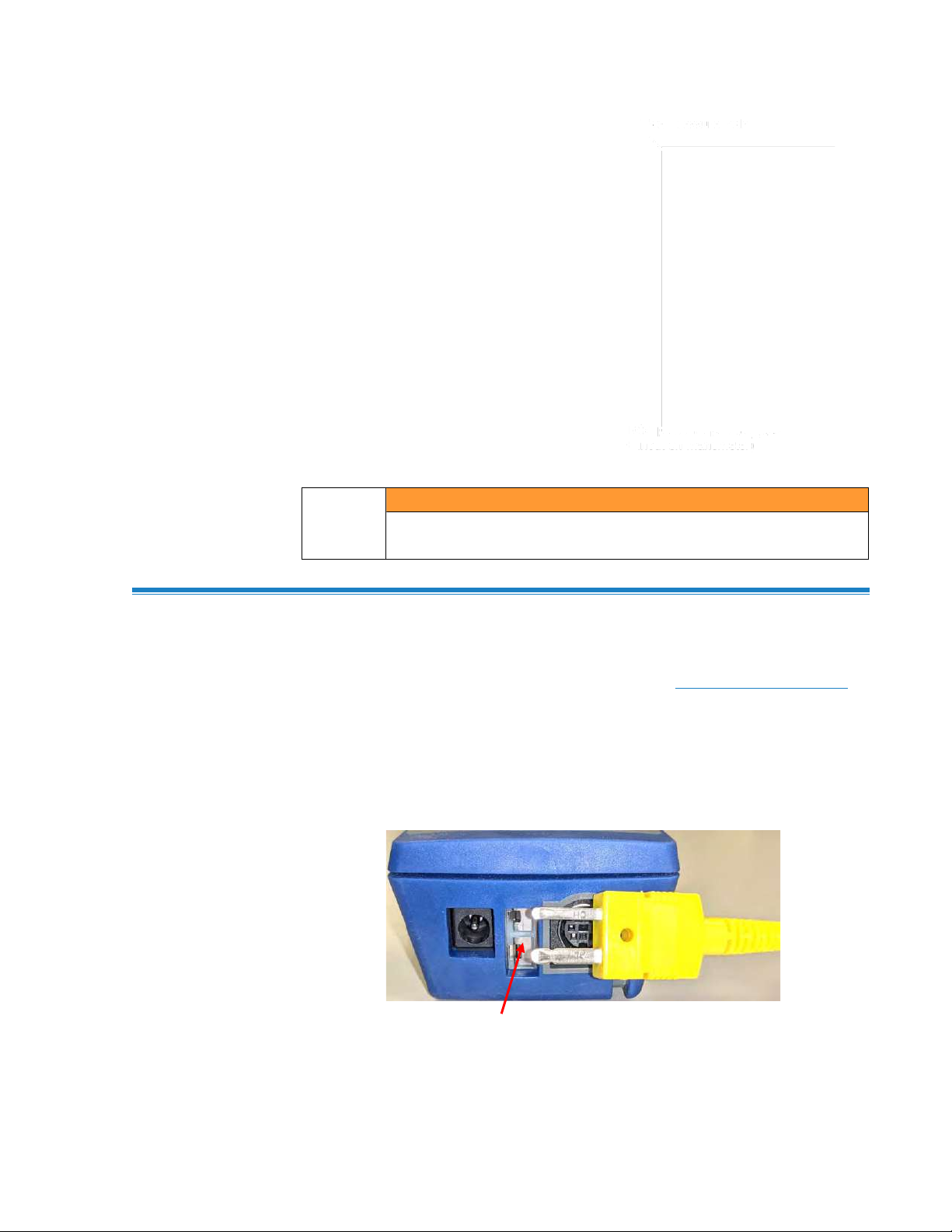
K-alloy Thermocouple
TC
Thermocouple Port
The 9600 Series VelociCalc® Air Velocity Meter includes a
thermocouple port at the base of the meter. Any K-alloy thermocouple
with mini-connector can be attached. See Chapter 4, Display Order
for displaying the thermocouple measurement.
Connecting the Thermocouples
The K-alloy thermocouple with mini-connector has one terminal wider
than the other. The wider terminal will be inserted into the bottom of
the TC connector port.
Find Quality Products Online at: sales@GlobalTestSupply.com
www.GlobalTestSupply.com
Operation and Service Manual 9
Page 20

W A R N I N G S
• Thermocouples from an alternate TSI® supplier must have the
metal sheath electrically isolated from the wires inside. Failure
to meet this requirement may result in false readings, electrical
shock, or fire hazard.
• DO NOT use the instrument or probes near hazardous voltage
sources since serious injury could result.
To connect the Bluetooth® printer to
the Model 9650, power on the unit
and the printer.
1. Navigate to Settings ->
Bluetooth and Enable
Bluetooth checkbox.
2. Highlight SCAN and
press Enter.
3. The unit will scan and find
compatible Bluetooth® printers.
4. Highlight printer and
press Enter.
5. The unit will display a message
of “Connected” when
successful.
Connecting the O p t i o n a l B l u e t o o t h® Portab l e Printer De v ic e ( M o d e l 9650 only)
Find Quality Products Online at: sales@GlobalTestSupply.com
10 VelociCalc®/VeloCalc® Pro Air Velocity Meter 9600 Series
Bluetooth is a registered trademark of Bluetooth SIG.
www.GlobalTestSupply.com
Page 21

C A U T I O N
Protection provided by the instrument could be impaired if used in
a manner other than specified in this user manual.
USB Communications Port
Connecting to a C o m p u t e r
Use the Computer Interface USB Cable provided with the VelociCalc®
meter to connect the instrument to a computer for downloading
stored data.
Find Quality Products Online at: sales@GlobalTestSupply.com
www.GlobalTestSupply.com
Operation and Service Manual 11
Page 22
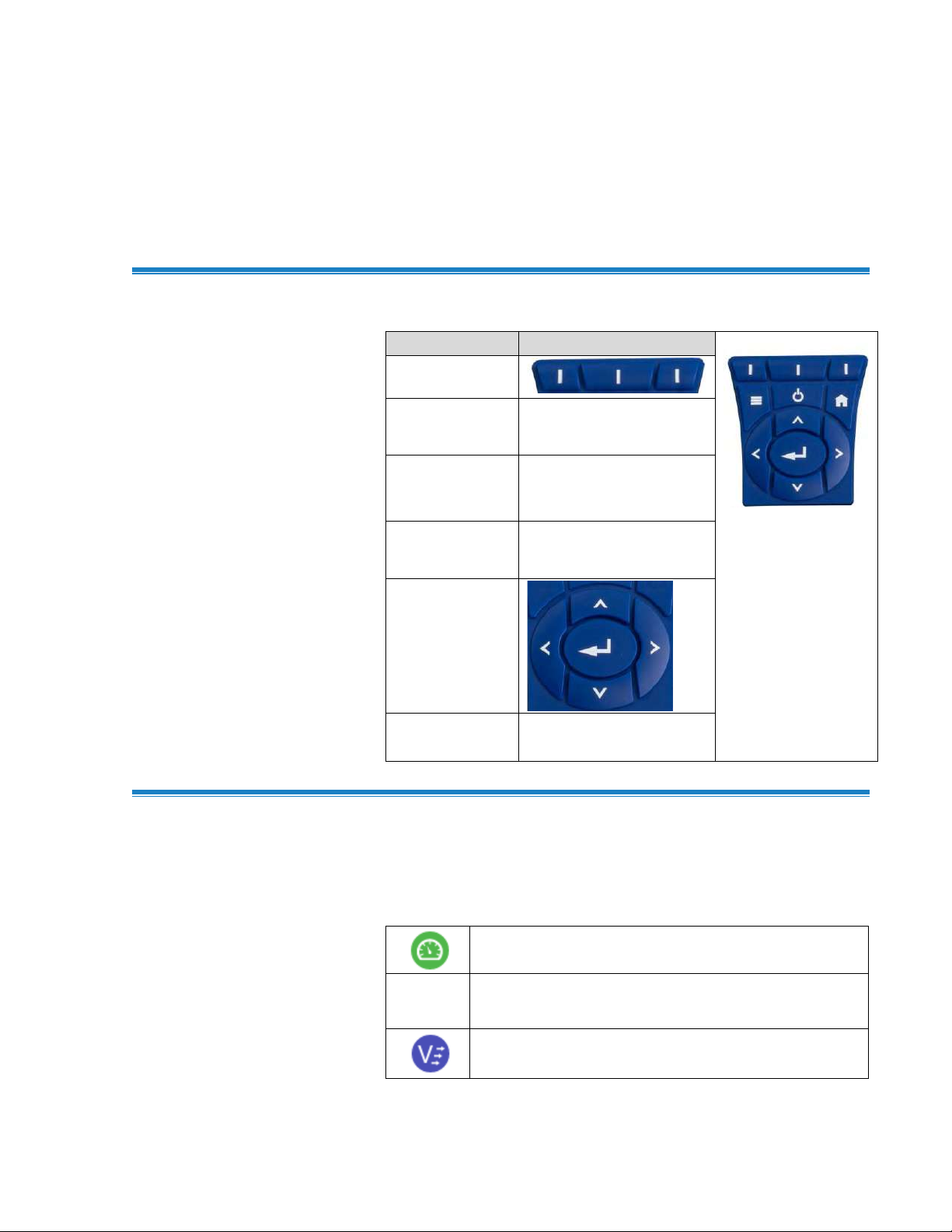
Button Names
Button Image
Programmable
Soft Keys
Main Menu
Power
Home
(Dashboard)
Navigation
Keys
Enter or OK
Barometric pressure
Temperature from thermocouple probe
Velocity from thermoanemometer or rotating vane
anemometer probe
C H A P T E R 3
Operational Overview
Keyp a d B u t t o n N a m e s
Icons
Measurement Icons
The visibility of the following icons are dependent on the type of meter
used and the probe connected.
Find Quality Products Online at: sales@GlobalTestSupply.com
www.GlobalTestSupply.com
13
Page 23
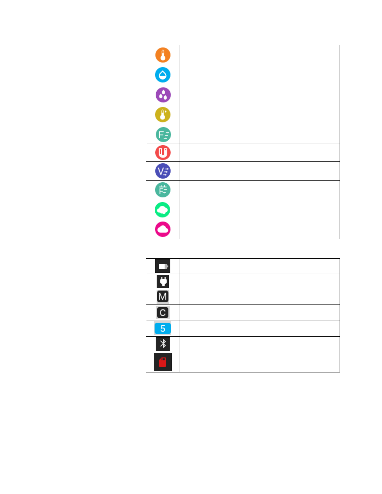
Temperature
Relative humidity
Dew point temperature
Wet bulb temperature
Air flow from thermoanemometer or rotating vane
anemometer probe
Differential pressure
Velocity from pitot probe
Airflow from pitot probe or K-factor
Carbon dioxide
Carbon monoxide
Battery status
AC power
Manual Logging mode
Continuous Logging mode
Number of samples
Bluetooth enabled (9650 only)
Memory low warning when 90% full
Dashboard Icons
14 VelociCalc®/VeloCalc® Pro Air Velocity Meter 9600 Series
Find Quality Products Online at: sales@GlobalTestSupply.com
www.GlobalTestSupply.com
Page 24

Save a sample
Cancel sample measurement in process
Closes a TestID and automatically increments to the
next available TestID
Display average measurements of current TestID
Close display of average measurements of
current TestID
Progress indicator
Go back to previous screen
Advance to next screen
Add a configuration
Delete
Delete all
Cancel and close Test ID
Restore factory calibration
Firmware update
Samples
Statistics
Manage data
Soft Key Icons
Programmable Soft Key Icons
Operation and Service Manual 15
Find Quality Products Online at: sales@GlobalTestSupply.com
www.GlobalTestSupply.com
Page 25
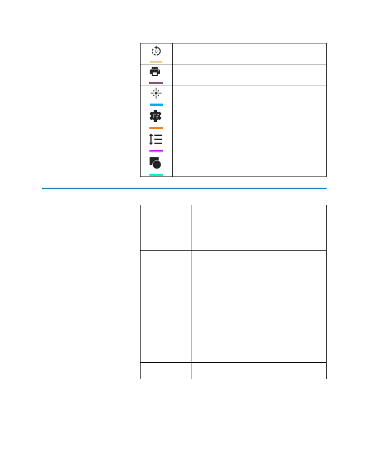
Zero differential pressure (9630, 9650, 9650-NB)
Print
Logging profile
Flow setup
Display order
Duct traverse (9650, 9650-NB)
Definitions
Out-of-Range
(Calibration)
An Out-of-Range error during the calibration of
a sensor means the sensor’s offset or
calibration slope adjustment has drifted outside
of the TSI® recommended specification for
continued use. Sensor should be replaced or
sent to TSI® for recalibration.
Test Duration
The time over which the data will be logged
while in Continuous Save mode. The test
duration can be set from 0 seconds 0 hours and
0 minutes to 99 hours: 59 minutes: 59 seconds.
If set to 0 seconds, 0 hours, 0 seconds, the
meter will not stop logging in continuous save
mode until the user presses the enter key.
Sample
Duration /
Time Constant
The sample duration / time constant is the time
period where data is collected and averaged to
produce a single value. For example, if the
sample duration / time constant is set to
5 seconds, each 1 second sample will be
averaged over the 5 seconds in a single value.
The sample interval / time constant can be set
to 1, 5, 10, 20, 30, 60 or 90 seconds.
Sample Interval
The frequency that the meter will log data while
in Continuous Save mode.
Find Quality Products Online at: sales@GlobalTestSupply.com
16 VelociCalc®/VeloCalc® Pro Air Velocity Meter 9600 Series
www.GlobalTestSupply.com
Page 26
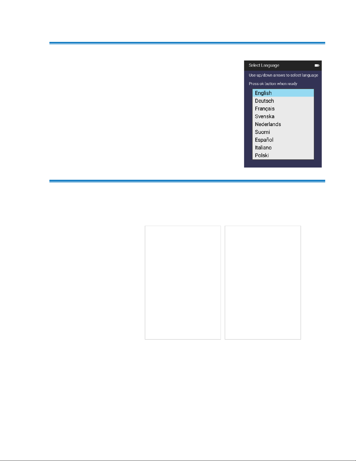
A language selection list is
displayed the first time the
meter is powered on.
Language Sele c t i o n
Dashboard
Dashboard
This is the main page for viewing live readings and logging data.
Press the any time to return to the Dashboard (Home) page.
If ˅ or ˄ is displayed, press the Up or Down button on the keypad to
view additional measurements.
To change the dashboard to display more measurements in a list
view, press the left or right navigation button on the keypad.
Operation and Service Manual 17
Find Quality Products Online at: sales@GlobalTestSupply.com
www.GlobalTestSupply.com
Page 27

NOT ICE
Measurements will only appear in the Dashboard page once they
have been configured as visible in the Display Order page.
The Dashboard offers a feature
called Programmable Soft Keys.
Programmable Soft Keys allows
you to create shortcuts to other
areas of interest in the meter.
Press and hold any of the top
3 keys (soft keys) for 3 seconds
to configure.
Programmable Soft Keys can be
configured to reach the following
screens or features with one
button press:
• Zero Pressure (9630,9650,
9650-NB only)
• Print
• Logging Profile
• Flow Setup
• Display Order
• Duct Traverse (9650 and
9650-NB)
• Samples
• Statistics
• Manage Data
Log Mode
Battery or AC Adapter
Current Test ID
Number of Samples
Air Density Setting
Measurements
Close Test ID
Display Average
of current test ID
Assign P r o g r a m m a b l e S o f t Keys
Find Quality Products Online at: sales@GlobalTestSupply.com
18 VelociCalc®/VeloCalc® Pro Air Velocity Meter 9600 Series
www.GlobalTestSupply.com
Page 28
Main Menu
Press the button to bring up
the main menu.
NOT ICE
The Main Menu items
displayed are dependent on
the meter model and connected
probe. Zero Pressure will be
displayed on Models 9630,
9650 and 9650-NB. Zero CO
will be displayed if the 982
probe is connected to any
instrument model.
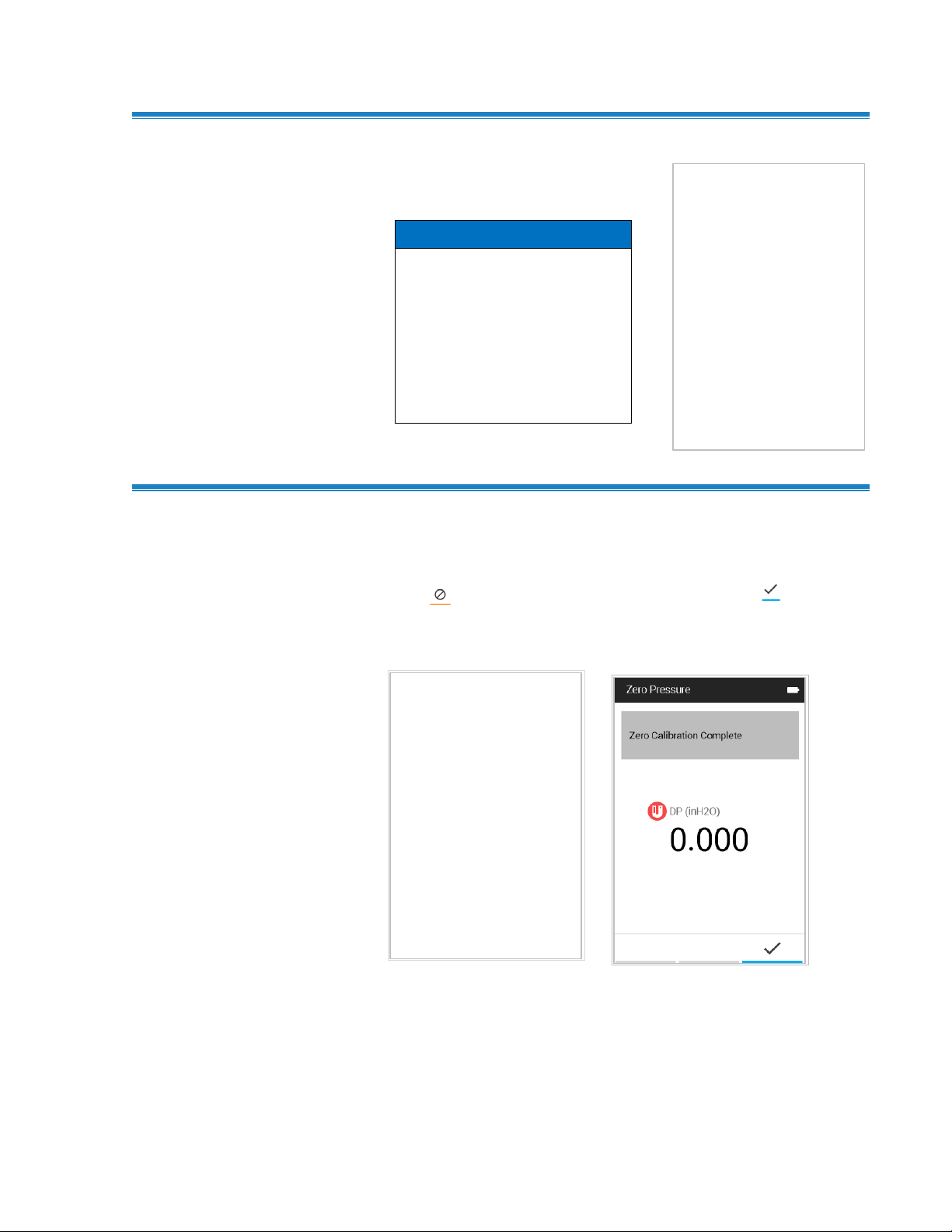
Zero Press ure
Select Zero Pressure from the Main Menu to zero the pressure
measurement.
Press to Cancel. When zeroing is complete, press or
to Save.
Zero Pressure applies to Models 9630, 9650, and 9650-NB.
Find Quality Products Online at: sales@GlobalTestSupply.com
www.GlobalTestSupply.com
Operation and Service Manual 19
Page 29

Settings
Select Settings from the
Main Menu, to view the Settings
page options. Refer to Chapter 4,
Settings for detailed information
about the device setting options.
Select Flow Setup to define duct
sizes and choose a duct shape.
Flow Setup is also used to set up
pressure K-factors on Models 9630
and 9650 or to select air cones
when the 995 probe is connected
to any meter model.
Flow Setup
20 VelociCalc®/VeloCalc® Pro Air Velocity Meter 9600 Series
Find Quality Products Online at: sales@GlobalTestSupply.com
www.GlobalTestSupply.com
Page 30

Workflows
Select Workflows from the
Main Menu, to view the Workflow
options. Refer to Chapter 7,
Workflows for detailed information
about the device setting options.
Duct Traverse and Heat Flow are
only available on the 9650 and
9650-NB.
Select Logging Profile to select
between Manual Mode logging and
Continuous Mode logging. See
Chapter 5, Manual Mode
Logging/Continuous Mode Logging
for detailed information.
Logging Profile
Operation and Service Manual 21
Find Quality Products Online at: sales@GlobalTestSupply.com
www.GlobalTestSupply.com
Page 31

Manage Da t a
Select Manage Data to display
logged data stored in the device.
Refer to Chapter 6, Manage Data
for detailed information.
22 VelociCalc®/VeloCalc® Pro Air Velocity Meter 9600 Series
Find Quality Products Online at: sales@GlobalTestSupply.com
www.GlobalTestSupply.com
Page 32

Navigate to the Settings page
by selecting Settings from the
Main Menu.
The Settings page options are:
• Display Order
• Actual/Standard
• Calibration
• General Settings
• Unit Settings
• Date and Time
• Display/Power
• Device Information
The Display Order screen is used to
configure what measurements are
displayed on the Dashboard page,
and the order they are displayed.
The list of measurements includes
the following information:
• A measurement icon and name.
• A toggle icon to enable or
disable the Visibility of the
measurement on the
Dashboard page.
• A positioning icon sets the
order of measurements
shown on the dashboard.
Use the buttons to
navigate the list and to
make adjustments.
C H A P T E R 4
Settings
Display Or der
Find Quality Products Online at: sales@GlobalTestSupply.com
www.GlobalTestSupply.com
23
Page 33

NOT ICE S
• The order of measurements on the Display Order page is the
order shown on the Dashboard page.
• Only those measurements configured as visible on the
Display Order page are logged to a TESTID.
Select Actual/Standard to
configure the settings used for
velocity and flow measurements.
The Calibration menu lists
measurement parameters that can
be adjusted in the field. The
appropriate detachable probes must
be attached to the VelociCalc® meter
before adjustments can be made.
Actual/Stan dar d
Calibration
Find Quality Products Online at: sales@GlobalTestSupply.com
24 VelociCalc®/VeloCalc® Pro Air Velocity Meter 9600 Series
www.GlobalTestSupply.com
Page 34

Calibration Offset Adjustments Applicable Models
Temperature
Barometric Pressure
Relative Humidity
960, 962,
964, 966,
980, 982,
800220
9600, 9630, 9650,
9650-NB
964, 966, 980, 982, 995,
800220
You can apply offset adjustments
to temperature, relative humidity,
and barometric pressure. The
measurement displayed and
logged will be the raw
measurement added to the value
you specify here. Offsets will be
shown on the dashboard if the
value is other than 1. Enter 0 to
return to default.
Correction Factors Applicable Models
Pitot Velocity
Pitot Flow
Probe Flow
9630, 9650, 9650NB
9630, 9650, 9650-NB
960, 962, 964, 966,
995
You can apply correction factors to
pitot velocity, pitot flow and thermal
anemometer and rotating vane air
flows. The measurement displayed
and logged will be the raw
measurement multiplied by the
value you specify here. Correction
factors will be shown on the
dashboard if the value is other than
1. Enter 1.000 to return to default.
IAQ Probe Calibration Applicable Models
Carbon Dioxide (CO2)
Carbon Monoxide (CO)
980, 982
982
Find Quality Products Online at: sales@GlobalTestSupply.com
www.GlobalTestSupply.com
Operation and Service Manual 25
Page 35

A probe calibration collar (included
with the 980 and 982 probes), zero
calibration gas, span calibration
gas, gas regulator and tubing are
required to perform the calibration.
The gas regulator used to control
the flow should be capable of
providing 0.3 L/min. Follow the onscreen instructions to complete the
calibration, the procedure is the
same for both carbon dioxide
(CO2) and carbon monoxide (CO).
The General Settings page is used
to configure the following functions:
• Language is used to select the
desired language shown on the
instrument.
• Number Format is used to
select the preferred decimal
separator.
• Time Constant (Sample
Duration) is used to adjust the
averaging period for all
measurements and to set the
sample duration for logging.
• When Sound Enabled is
active, the meter will sound
when any button is pressed.
General Se t t i n g s
Find Quality Products Online at: sales@GlobalTestSupply.com
26 VelociCalc®/VeloCalc® Pro Air Velocity Meter 9600 Series
www.GlobalTestSupply.com
Page 36

NOT ICE
Time Constant is the display averaging period. The display will
update every second; however, the displayed reading will be the
average over the time constant period. For example, if the time
constant is 5 seconds, the display will update every second, but
the displayed reading will be the average of the last 5 seconds.
Unit Setti ngs
The Unit Settings page is used to
configure the desired unit of
measure for each measurement.
The Date and Time page is used to
configure the desired formats for
date and time and to set device
date and time.
Date and Time
Find Quality Products Online at: sales@GlobalTestSupply.com
www.GlobalTestSupply.com
Operation and Service Manual 27
Page 37

The Display/Power page is used
to configure the following functions
• Screen Brightness adjusts the
brightness of the display.
• Automatic Shutdown enables
and disables automatic
shutdown. If enabled, the meter
will shut itself off after
20 minutes of inactivity.
To display general information
about the VelociCalc® Air Velocity
Meter, select Device Information
from the Settings Menu. The
Device Information page lists the
meter model number, serial
number, and many other
characteristics of the device,
including information about the
attached probe.
Display/Power
Device Info r m a t i o n
To update the VelociCalc® meter firmware, press the update firmware
soft key and follow the instructions provided.
28 VelociCalc®/VeloCalc® Pro Air Velocity Meter 9600 Series
Find Quality Products Online at: sales@GlobalTestSupply.com
www.GlobalTestSupply.com
Page 38
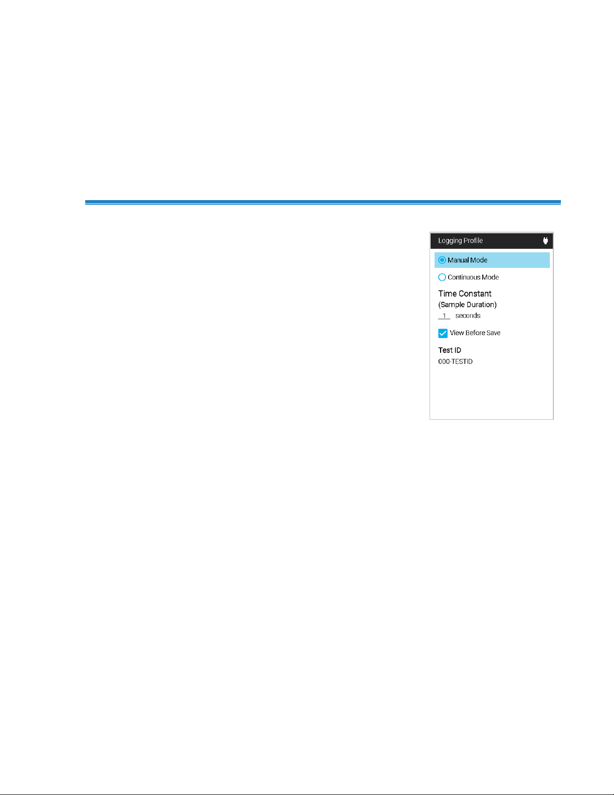
To configure the meter to log when
the Enter button is pressed, select
Manual Mode.
View Before Save prompts you to
either SAVE or DISCARD once the
sample is complete.
The Time Constant (Sample
Duration) setting determines
how long all measurements are
averaged for.
C H A P T E R 5
Logging Profile and
Custom TESTID Labels
Manual Mode L o g g i n g
29
Find Quality Products Online at: sales@GlobalTestSupply.com
www.GlobalTestSupply.com
Page 39

To configure the meter to log
continuously, select
Continuous Mode.
The Time Constant (Sample
Duration) setting determines how
long all measurements are
averaged for.
The Sample Interval sets the
frequency that the meter will log
measurements on the dashboard to
a TESTID.
The Test Duration sets how long the
meter will log data. If this setting is
set to 00:00:00, the meter will log
until the Enter button is pressed.
NOT ICE
On-board memory is capable of
storing data from all available
measurements for more than
30 days when sampling data once
a minute in continuous mode.
Continuous Mo de L o g g i n g
Find Quality Products Online at: sales@GlobalTestSupply.com
Custom i z e T E S T I D L a b e l s in Meter
To change a TESTID label, highlight the TESTID field and
press .
Then highlight the desired TESTID and press .
Use the navigation keys to update the test ID label.
Press the Check key to accept the new label.
Press the Cancel key to discard label changes.
30 VelociCalc®/VeloCalc® Pro Air Velocity Meter 9600 Series
www.GlobalTestSupply.com
Page 40

NOT ICE
To scroll through the list of TESTIDs faster, press to page
down and to page up through the list.
Customize T ES T I D L a b e l s u s i n g T e s t I D . c s v
The VelociCalc® Air Velocity Meter also allows TESTID label updates
using Excel® spreadsheet program.
Plug the VelociCalc® meter into a computer using the supplied
USB cable.
Navigate to the “TSI9600_LOG” drive and open the TestIDs.csv file.
Modify labels in column B.
Save the new TestIDs.csv file to the “TSI9600_LOG” drive and close
the file. All TESTID labels that were changed will be updated in the
VelociCalc® meter when the USB cable is disconnected.
Operation and Service Manual 31
Find Quality Products Online at: sales@GlobalTestSupply.com
www.GlobalTestSupply.com
Page 41

NOT ICE
TESTID labels are limited to 6 characters. Any additional
characters will be discarded.
32 VelociCalc®/VeloCalc® Pro Air Velocity Meter 9600 Series
Find Quality Products Online at: sales@GlobalTestSupply.com
www.GlobalTestSupply.com
Page 42
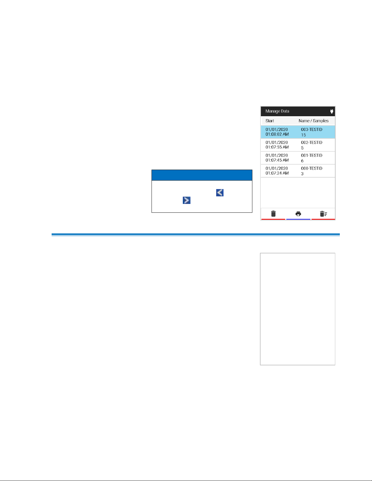
From the Main Menu, select
Manage Data.
The Manage Data page contains all
TESTIDs on the device. You can
select a log file for viewing or
deleting, as well as scroll through a
list of log files.
NOT ICE
To scroll through the list of
TESTIDs faster, press to page
down and to page up through
the list.
To view a log file (TESTID),
navigate to the log file on the
Manage Data list and press the
to open the Statistics page.
C H A P T E R 6
Manage Data
Viewing a L o g F i l e ( T E S T ID)
Find Quality Products Online at: sales@GlobalTestSupply.com
www.GlobalTestSupply.com
33
Page 43

To view Samples in a log file
TESTID, navigate to the desired
measurement in the Statistics
page and press key.
NOT ICE
Deleted log files CANNOT be recovered.
Viewing Sa m p l e s
Delete Log F i l e s
Opening L o g C S V F i l e s on a PC
Select a log file then select the icon to delete it. Next select YES.
Log CSV files can be accessed on the VelociCalc® Series 9600
meters by connecting the meter to a computer using the supplied
USB cable.
Connect the VelociCalc® meter to a PC over the supplied USB cable.
A “please wait” message will appear on the VelociCalc® meter.
After the “please wait” message disappears, a TSI9600_LOG drive
will show up on the computer that looks like this:
Open the TSI9600_LOG drive to view or download TESTID CSV files:
34 VelociCalc®/VeloCalc® Pro Air Velocity Meter 9600 Series
Find Quality Products Online at: sales@GlobalTestSupply.com
www.GlobalTestSupply.com
Page 44

NOT ICE
Displayed workflows are dependent on instrument model and
attached probe. Percent Outside air will be shown if a probe that
measures air temperature or CO2 is connected. Heat Flow will be
shown on the 9650 or 9650-NB if a 964 or 966 probe is attached.
Duct traverse will be shown on the 9650 or 9650-NB and is used
with the differential pressure sensor or a connected probe that
measures air velocity.
After selecting Workflows from the
Main Menu, select % Outside Air
to view the % Outside Air screen.
C H A P T E R 7
Workflows
Workflows step you through the measurement process and assist in
calculating and logging the measurement points.
The following workflows are available:
• Percent Outside Air (%OA) (9600, 9630, 9650, 9650-NB)
• Heat Flow (9650, 9650-NB with 964 or 966 probe)
• Duct Traverse (9650, 9650-NB)
Percent O u t s i d e A i r ( % OA) Calculation Procedure
Find Quality Products Online at: sales@GlobalTestSupply.com
www.GlobalTestSupply.com
35
Page 45

The Percent Outside Air feature
offers the choice between using
Temperature or CO2 for the Percent
Outside Air study if a probe that
supports either CO2 or Temperature
is plugged in.
Three measurements are necessary
for Percent Outside Air calculations:
Outside Air, Supply Air, and
Return Air.
The measurements may be taken in
any order by using the navigation
keys and . The Percent
Outside Air calculation is displayed
once the final measurement is taken.
IMP O R TANT NO TI CE
The VelociCalc® instrument is intended for indoor use only. Care
should be taken when taking Percent Outdoor Air measurements
so that the instrument is not exposed to rain, sleet, hail, snow, or
other inclement weather conditions as exposure to these elements
will void the factory warranty.
The instrument calculates heat flow
by making temperature, humidity, and
flow measurements upstream and
downstream of the coil in the duct.
The following steps are utilized to
make the heat flow measurement:
• Select Heat Flow under the
workflows menu.
NOT ICE
Heat Flow will only be available
with probes that measure Velocity,
Temperature, and Humidity (964
and 966 probes).
Heat Flow Proce dure
Find Quality Products Online at: sales@GlobalTestSupply.com
36 VelociCalc®/VeloCalc® Pro Air Velocity Meter 9600 Series
www.GlobalTestSupply.com
Page 46
• Upstream measurements of Flow,
Temperature, and Humidity are
displayed. Press to capture
these upstream measurements.
o Press to accept the
upstream readings
o Press to retake
upstream readings
• After upstream measurement has
been accepted, place probe
downstream of the coil.
o Press to capture these
upstream measurements.
o Press to accept the
upstream readings
o Press to retake
upstream readings
• Press to save and close the
test ID.
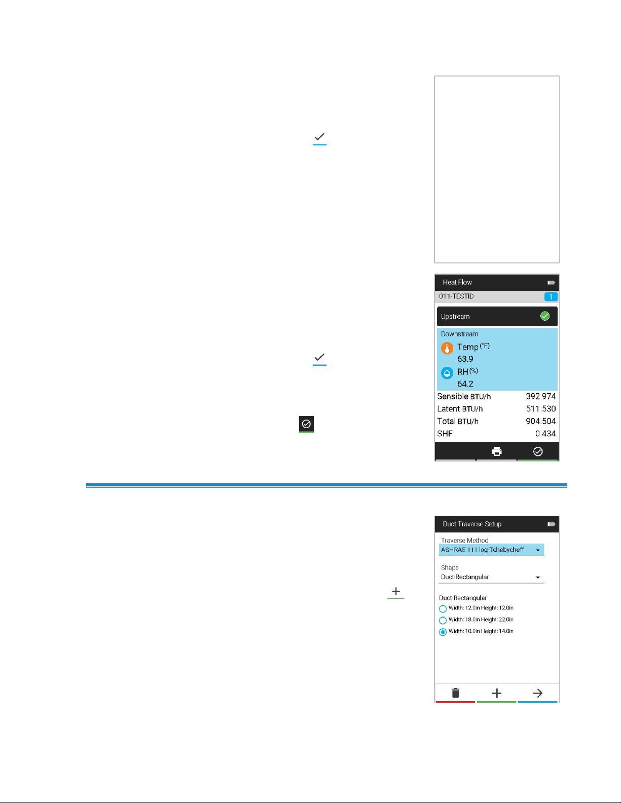
After connecting any TA Probe or
Pitot tube and selecting Workflows
from the Main Menu, select Duct
Traverse to view the Duct
Traverse Setup screen.
To add a new duct size press .
Duct Trave r s e P r o c e d u r e (9650, 9650 - NB)
Operation and Service Manual 37
Find Quality Products Online at: sales@GlobalTestSupply.com
www.GlobalTestSupply.com
Page 47
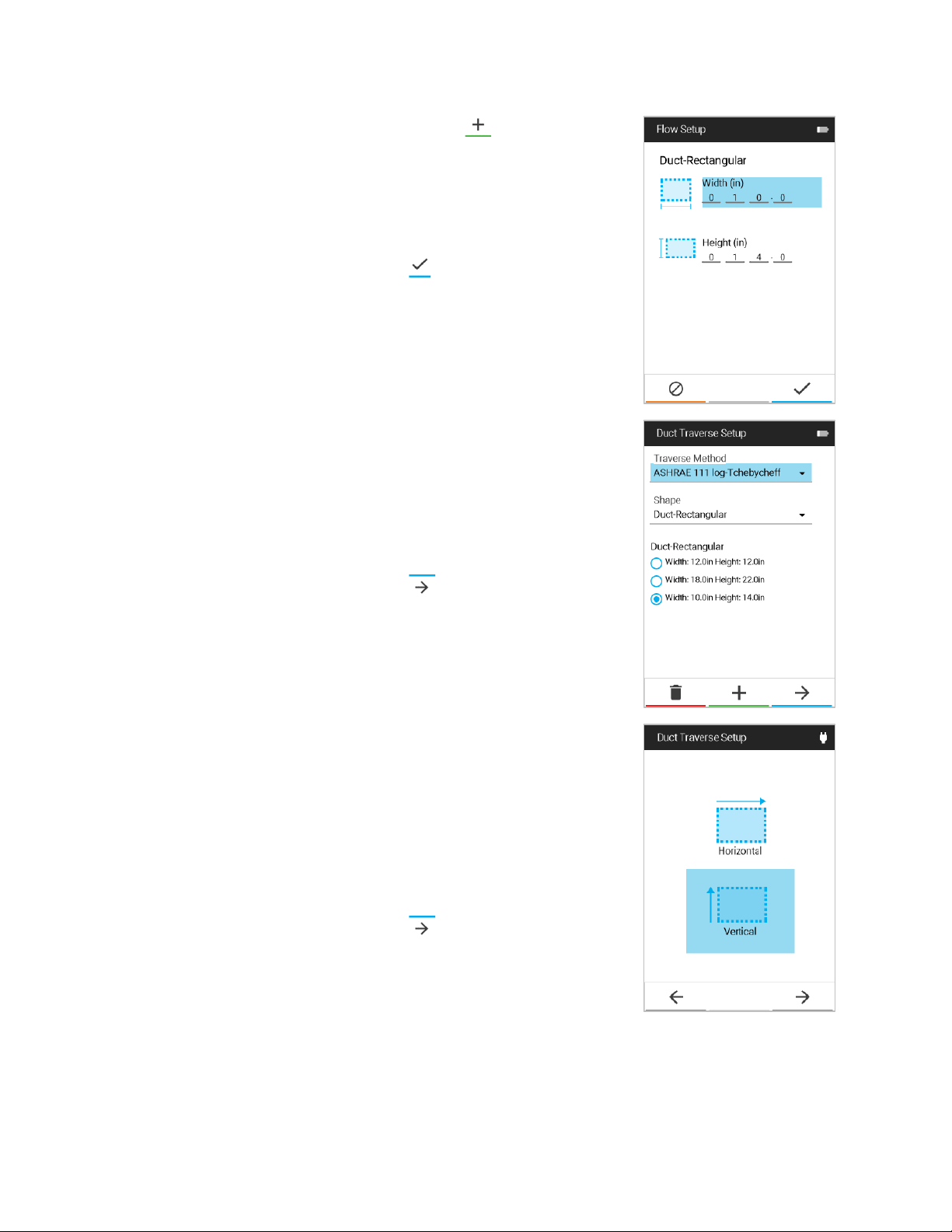
After pressing to add a new
duct size, you are brought to the
Flow Setup page. To change the
dimensions, use the arrow keys to
navigate between Width and Height
then press to begin editing the
numbers by using the arrow keys.
Press to save the new duct size.
To create a circular duct, select
Duct-Circular on the Duct Traverse
Setup screen before adding a
duct size.
Creating a new duct size will bring
you back to the Duct Traverse
Setup screen. Select the desired
Traverse Method and Duct Shape
with the drop-down menus and
select the desired duct size using
the navigation keys.
Press to move onto the
next screen.
After choosing the traverse method
and duct shape and size, you will
select a traverse orientation
(rectangular only, screen is skipped
for circular ducts). For traverse
holes on the side of a rectangular
duct, select horizontal traverse. For
traverse holes on the bottom of a
rectangular duct, select vertical.
Press to move on.
Find Quality Products Online at: sales@GlobalTestSupply.com
38 VelociCalc®/VeloCalc® Pro Air Velocity Meter 9600 Series
www.GlobalTestSupply.com
Page 48

After selecting the traverse
orientation (or after selecting
a circular duct), the Insertion
Depths screen will be shown.
Note these insertion depths
before proceeding.
Press to proceed to the
Duct Traverse working screen.
Insert your probe into the first
position indicated by the blue circle
(traverse starts in the bottom left of
the grid). If you prefer to start at a
different point, use the navigation
arrow keys to navigate to a
different spot in the grid first. To
take a velocity measurement,
press . The position will
automatically move up to the next
measurement point after taking a
measurement. Note that the
Previous measurement and the
Average of all measurements
taken will display across the
bottom. Pressing will display
flow measurements and to
display velocity measurements.
After taking a velocity
measurement at every grid
location, the traverse is complete
and you will be prompted to press
to accept the traverse. Before
accepting the traverse, you may go
back and retake any measurement
by navigating to that point with the
navigation keys. When you are
ready, press to complete and
accept the Duct Traverse. The
traverse will save to the TESTID
noted in the top left.
Find Quality Products Online at: sales@GlobalTestSupply.com
www.GlobalTestSupply.com
Operation and Service Manual 39
Page 49

C A U TI ON
DO NOT use strong solvents like ammonia to avoid damaging the
meter’s display.
DO NOT use paper-based cloths like paper towels to avoid
scratching surfaces.
DO NOT use disinfectants that contain phenol.
DO NOT clean with strong aromatic, chlorinated, ketone, ether, or
Esther solvents, sharp tools or abrasives.
C H A P T E R 8
Maintenance
Cleaning / D i s i n f e c t i n g
• Ensure the VelociCalc® meter is turned off and not plugged into
the AC/DC power supply.
• DO NOT spray directly onto the product.
• DO NOT get liquids inside the unit.
• For cleaning, wet a soft lint-free or microfiber cloth with a mild
soapy solution then wipe the screen and meter case in a gentle
motion to remove dust, oil, or fingerprint smudges.
• For disinfecting, the following is a recommended list of
disinfectant solutions:
o Household bleach solution (1/3 cup or 79 ml of bleach per
one (1) gallon or 3.8 L of water)
o Isopropyl alcohol (≤ 70% alcohol)
o 6% Hydrogen peroxide (H₂O₂)
• Hot water with soap can be used to remove sticky substances
when necessary.
• Wipe any moisture excess with a dry lint-free or microfiber cloth
to finish cleaning before turning the meter back on.
Find Quality Products Online at: sales@GlobalTestSupply.com
41
www.GlobalTestSupply.com
Page 50

Bi-Annual Ma i n t e n a n c e C h e cks
• Make sure there are no cracks on the meter case. Cracks can
create inconsistencies with how the electronics are supported
inside the case, which can lead to damages.
• Inspect the power supply and cable to make sure they have not
degraded. Replace if you find any cracks in the power supply or
cable as it might cause shorting.
42 VelociCalc®/VeloCalc® Pro Air Velocity Meter 9600 Series
Find Quality Products Online at: sales@GlobalTestSupply.com
www.GlobalTestSupply.com
Page 51

CH A P T E R 9
Symptom
Possible Causes
Corrective Action
No Display
Unit not turned on
Switch unit on.
Low or dead batteries
Replace batteries or plug
in AC/DC power supply.
Dirty battery contacts
Clean the battery
contacts.
Velocity reading
fluctuates unstable
Fluctuating flow
Reposition probe in less
turbulent flow or use
longer time constant.
Instrument shows a
memory full
message and
cannot log
more data
Memory is full
Download data if desired
then DELETE ALL memory.
Probe Error
message appears
Fault in probe
Factory service required
on probe.
Troubleshooting
Table 1 lists the symptoms, possible causes, and recommended
solutions for common problems encountered with the VelociCalc® Air
Velocity Meter. If your symptom is not listed, or if none of the
solutions solves your problem, please contact
Table 1. Troubleshooting the VelociCalc® Air Velocity Meter
Find Quality Products Online at: sales@GlobalTestSupply.com
www.GlobalTestSupply.com
43
Page 52

960 Thermoanemometer Straight Probe Velocity
and Temperature
Range: .....................
0 to 9999 ft/min (0 to 50 m/s), 0 to 200°F
(-18 to 93°C)
Accuracy: .................
±3% of reading or ±3 ft/min (±0.015 m/s),
whichever is greater1&2, ±0.5°F (±0.3°C)5
Resolution: ..............
1 ft/min (0.01 m/s), 0.1°F (0.1°C)
962 Thermoanemometer Articulating Probe Velocity
and Temperature
Range: .....................
0 to 9999 ft/min (0 to 50 m/s), 0 to 200°F
(-18 to 93°C)
Accuracy: .................
±3% of reading or ±3 ft/min (±0.015 m/s),
whichever is greater
1&2
, ±0.5°F (±0.3°C)5
Resolution: ..............
1 ft/min (0.01 m/s), 0.1°F (0.1°C)
964 Thermoanemometer Straight Probe Velocity, Temperature,
Humidity, Wet Bulb, and Dew Point
Range: .....................
0 to 9999 ft/min (0 to 50 m/s), 14 to 140°F
(-10 to 60°C), 5 to 95% RH
Accuracy: .................
±3% of reading or ±3 ft/min (±0.015 m/s),
whichever is greater
1&2
, ±0.5°F (±0.3°C)5,
±3% RH6
Resolution: ..............
1 ft/min (0.01 m/s), 0.1°F (0.1°C), 0.1% RH
966 Thermoanemometer Articulating Probe Velocity,
Temperature, Humidity, Wet Bulb, and Dew Point
Range: .....................
0 to 9999 ft/min (0 to 50 m/s), 14 to 140°F
(-10 to 60°C), 5 to 95% RH
Accuracy: .................
±3% of reading or ±3 ft/min (±0.015 m/s),
whichever is greater
1&2
, ±0.5°F (±0.3°C)5,
±3% RH6
Resolution: ..............
1 ft/min (0.01 m/s), 0.1°F (0.1°C), 0.1% RH
960 and 964 Thermoanemometer Probe Dimensions
Probe Length: ..................
40 in. (101.6 cm)
Probe Diameter of Tip: ....
0.28 in. (7.0 mm)
Probe Diameter of Base: .
0.51 in. (13.0 mm)
A P P E N D I X A
Specifications
Specifications are subject to change without notice.
Find Quality Products Online at: sales@GlobalTestSupply.com
www.GlobalTestSupply.com
47
Page 53

962 and 966 Thermoanemometer Probe Dimensions (962, 966)
Probe Length: ...............................
40 in. (101.6 cm)
Probe Diameter of Tip: .................
0.28 in. (7.0 mm)
Probe Diameter of Base: ..............
0.51 in. (13.0 mm)
Articulating Section Length: ..........
6.0 in. (15.24 cm)
Diameter of Articulating Knuckle: .
0.38 in. (9.5 mm)
Thermoanemometer Response Time
Velocity: ...................
200 msec
Temperature: ...........
2 minutes (to 66% of final value)
Humidity: ..................
<1 minute (to 66% of final value)
995 Rotating Vane 4 in. (100mm) Probe Velocity and
Temperature
Range: .....................
50 to 6000 ft/min (0.25 to 30 m/s),
32 to 140°F (0 to 60°C)
Accuracy: .................
±1% + 4 ft/min (±0.02 m/s), ±2.0°F (±1.0°C)
Resolution: ...............
1 ft/min (0.01 m/s), 0.1°F (0.1°C)
980 IAQ Probe CO2, Temperature and Humidity
Range: .....................
0 to 5000 ppm CO2, 5 to 95% RH,
14 to 140°F (-10 to 60°C)
Accuracy: .................
±3% of reading or ±50 ppm CO2, whichever
is greater9, ±3% RH6, ±1.0°F (±0.5°C)5
Resolution: ...............
1 ppm CO2, 0.1% RH, 0.1°F (0.1°C)
982 IAQ Probe CO, CO2, Temperature and Humidity
Range: .....................
0 to 500 ppm CO, 0 to 5000 ppm CO2,
5 to 95% RH, 14 to 140°F (-10 to 60°C)
Accuracy: .................
±3% of reading or ±3 ppm CO, whichever is
greater8, ±3% of reading or ±50 ppm CO2,
whichever is greater9, ±3% RH6, ±1.0°F
(±0.5°C)5
Resolution: ...............
0.1 ppm CO, 1 ppm CO2, 0.1% RH, 0.1°F
(0.1°C)
980 and 982 Probe Response Time
Carbon Dioxide: .......
20 seconds to 90% of final value.
Carbon Monoxide: ...
<60 seconds to 90% of final value.
Temperature: ...........
30 seconds (90% of final value, air velocity
at 400 ft/min [2 m/s])
Relative Humidity: ....
20 seconds (for 63% of final value)
Find Quality Products Online at: sales@GlobalTestSupply.com
48 VelociCalc®/VeloCalc® Pro Air Velocity Meter 9600 Series
www.GlobalTestSupply.com
Page 54

792 and 794 Thermocouple Probes Temperature
Range: .....................
-40 to 1200°F (-40 to 650°C)
Accuracy
5
:
................
±0.1% of reading +2°F
(±0.056% of reading +1.1°C)
Resolution: ..............
0.1°F (0.1°C)
Pitot Tubes (9630, 9650, 9650-NB)
Range3: ...................
250 to 15500 ft/min (1.27 to 78.7 m/s)
Accuracy4: ..............
±1.5% at 2000 ft/min (10.16 m/s)
Resolution: .............
1 ft/min (0.01 m/s)
Duct Size
Range: ....................
1 to 500 inches in increments of 0.1 in.
(2.5 to 1270 cm in increments of 0.1 cm)
Volumetric Flow Rate
Range: ....................
Actual range is a function of actual velocity,
pressure, duct size, and K-factor
Heat Flow (964 or 966 Probe with 9650, 9650-NB)
Range: ....................
Function of velocity, temperature, humidity,
and barometric pressure
Measurements
Available: ................
Sensible heat flow, latent heat flow, total
heat flow and sensible heat factor
Units Measured: .....
BTU/hr, kW
Static/Differential Pressure (9630, 9650, 9650-NB)
Range7: ...................
-15 to +15 in. H2O
(-28.0 to +28.0 mm Hg, -3735 to +3735 Pa)
Accuracy: .................
±1% of reading ±0.005 in. H2O
(±1 Pa, ±0.01 mm Hg)
Resolution: ..............
0.001 in. H2O (0.1 Pa, 0.01 mm Hg)
Barometric Pressure
Range: ............................
20.36 to 36.648 in. Hg (517.15 to
930.87 mm Hg)
Accuracy: ........................
±2% of reading
Instrument Temperature Range
Operating (Electronics): .
40 to 113°F (5 to 45°C)
Operating (Probe): ..........
14 to 140°F (-10 to 60°C)
Storage: ..........................
-4 to 140°F (-20 to 60°C)
Find Quality Products Online at: sales@GlobalTestSupply.com
www.GlobalTestSupply.com
Operation and Service Manual 49
Page 55

Instrument Operating Conditions
Altitude up to 4000 meters (only limited when plugged into the
AC/DC adapter)
Relative humidity up to 80% RH, non-condensing
Pollution Degree II
Overvoltage Category II
Data Storage Capabilities
Range: ............................
162,200 samples and 200 TESTIDs
(one sample can contain multiple
measurement types)
Logging Interval
Intervals: .........................
1 second to 1 hour
Time Constant
Intervals: .........................
User selectable
External Meter Dimensions
3.2 in. 9.5 in. 1.6 in. (8.1 cm 24.1 cm 4.1 cm)
Meter Weight
Weight with Batteries: .....
0.9 lbs (0.41kg)
Power Requirements
Four (4) AA-size batteries (included) or AC/DC power supply
P/N 6013125
Input: ...............................
100 to 240 VAC, 50 to 60 Hz, 1.0A
Output: ............................
12 VDC, 3.0A
1
Temperature compensated over an air temperature range of 40 to 150°F
(5 to 65°C).
2
The accuracy statement of ±3.0% of reading or ±3 ft/min (±0.015 m/s), whichever is
greater, begins at 30 ft/min through 9999 ft/min (0.15 m/s through 50 m/s).
3
Pressure velocity measurements are not recommended below 1000 ft/min (5 m/s) and
are best suited to velocities over 2000 ft/min (10.00 m/s). Range can vary depending
on barometric pressure.
4
Accuracy is a function of converting pressure to velocity. Conversion accuracy
improves when actual pressure values increase.
5
Accuracy with instrument case at 77°F (25°C), add uncertainty of 0.05°F/°F
(0.03°C/°C) for change in instrument temperature.
6
Accuracy with probe at 77°F (25°C). Add uncertainty of 0.1% RH/°F (0.2% RH/°C) for
change in probe temperature. Includes 1% hysteresis.
7
Overpressure range = 190 in. H2O (7 psi, 360 mmHg, 48 kPa).
8
At 77°F (25°C). Add uncertainty of ±0.2%/°F (0.36%/°C) for change in temperature.
9
At calibration temperature. Add uncertainty of ±0.28%/°F (0.5%/°C) for change
in temperature.
Find Quality Products Online at: sales@GlobalTestSupply.com
50 VelociCalc®/VeloCalc® Pro Air Velocity Meter 9600 Series
www.GlobalTestSupply.com
 Loading...