

Page 1
FMS SOFTWARE
VERSION 5
USER MANUAL
P/N 6002773, REVISION Q
OCTOBER 2020
Page 2

ii
Manual History
The following is a manual history of the FMS Software User Manual
(P/N 6002773).
Revision Date
A July 2009
B December 2009
C May 2010
D August 2010
E November 2010
F February 2011
G June 2012
H October 2012
J April 2014
K January 2015
L July 2015
M August 2016
N September 2017
P January 2019
Q October 2020
Page 3

iii
Warranty/ Software License
Part Number
6002773 / Revision Q / October 2020
Copyright
©TSI Incorporated / 2009-2020 / All rights reserved.
Address
TSI Incorporated / 500 Cardigan Road / Shoreview, MN 55126 / USA
E-mail Address
answers@tsi.com
Limitation of Warranty
and Liability
(effective April 2014)
(For country-specific terms and conditions outside of the USA, please visit www.tsi.com.)
Seller warrants the goods, excluding software, sold hereunder, under normal use and service as
described in the operator's manual, to be free from defects in workmanship and material for 12
months, or if less, the length of time specified in the operator's manual, from the date of
shipment to the customer. This warranty period is inclusive of any statutory warranty. This
limited warranty is subject to the following exclusions and exceptions:
a. Hot-wire or hot-film sensors used with research anemometers, and certain other components
when indicated in specifications, are warranted for 90 days from the date of shipment;
b. Pumps are warranted for hours of operation as set forth in product or operator’s manuals;
c. Parts repaired or replaced as a result of repair services are warranted to be free from defects in
workmanship and material, under normal use, for 90 days from the date of shipment;
d. Seller does not provide any warranty on finished goods manufactured by others or on any fuses,
batteries or other consumable materials. Only the original manufacturer's warranty applies;
e. This warranty does not cover calibration requirements, and seller warrants only that the
instrument or product is properly calibrated at the time of its manufacture. Instruments
returned for calibration are not covered by this warranty;
f. This warranty is VOID if the instrument is opened by anyone other than a factory authorized
service center with the one exception where requirements set forth in the manual allow an
operator to replace consumables or perform recommended cleaning;
g. This warranty is VOID if the product has been misused, neglected, subjected to accidental or
intentional damage, or is not properly installed, maintained, or cleaned according to the
requirements of the manual. Unless specifically authorized in a separate writing by Seller, Seller
makes no warranty with respect to, and shall have no liability in connection with, goods which
are incorporated into other products or equipment, or which are modified by any person other
than Seller.
The foregoing is IN LIEU OF all other warranties and is subject to the LIMITATIONS stated herein.
NO OTHER EXPRESS OR IMPLIED WARRANTY OF FITNESS FOR PARTICULAR PURPOSE
OR MERCHANTABILITY IS MADE. WITH RESPECT TO SELLER’S BREACH OF THE IMPLIED
WARRANTY AGAINST INFRINGEMENT, SAID WARRANTY IS LIMITED TO CLAIMS OF
DIRECT INFRINGEMENT AND EXCLUDES CLAIMS OF CONTRIBUTORY OR INDUCED
INFRINGEMENTS. BUYER’S EXCLUSIVE REMEDY SHALL BE THE RETURN OF THE
PURCHASE PRICE DISCOUNTED FOR REASONABLE WEAR AND TEAR OR AT SELLER’S
OPTION REPLACEMENT OF THE GOODS WITH NON-INFRINGING GOODS.
TO THE EXTENT PERMITTED BY LAW, THE EXCLUSIVE REMEDY OF THE USER OR
BUYER, AND THE LIMIT OF SELLER'S LIABILITY FOR ANY AND ALL LOSSES, INJURIES,
OR DAMAGES CONCERNING THE GOODS (INCLUDING CLAIMS BASED ON CONTRACT,
NEGLIGENCE, TORT, STRICT LIABILITY OR OTHERWISE) SHALL BE THE RETURN OF
GOODS TO SELLER AND THE REFUND OF THE PURCHASE PRICE, OR, AT THE OPTION
OF SELLER, THE REPAIR OR REPLACEMENT OF THE GOODS. IN THE CASE OF
SOFTWARE, SELLER WILL REPAIR OR REPLACE DEFECTIVE SOFTWARE OR IF UNABLE
TO DO SO, WILL REFUND THE PURCHASE PRICE OF THE SOFTWARE. IN NO EVENT
SHALL SELLER BE LIABLE FOR LOST PROFITS, BUSINESS INTERRUPTION, OR ANY
SPECIAL, INDIRECT, CONSEQUENTIAL OR INCIDENTAL DAMAGES. SELLER SHALL NOT
BE RESPONSIBLE FOR INSTALLATION, DISMANTLING OR REINSTALLATION COSTS OR
CHARGES. No Action, regardless of form, may be brought against Seller more than 12 months
Page 4

iv FMS Software User’s Manual
after a cause of action has accrued. The goods returned under warranty to Seller's factory shall
be at Buyer's risk of loss, and will be returned, if at all, at Seller's risk of loss.
Buyer and all users are deemed to have accepted this LIMITATION OF WARRANTY AND
LIABILITY, which contains the complete and exclusive limited warranty of Seller. This LIMITATION
OF WARRANTY AND LIABILITY may not be amended, modified or its terms waived, except by
writing signed by an Officer of Seller.
Service Policy
Knowing that inoperative or defective instruments are as detrimental to TSI as they are to our
customers, our service policy is designed to give prompt attention to any problems. If any malfunction is discovered, please contact your nearest sales office or representative, or call TSI’s
Customer Service department at 1-800-680-1220 (USA) or +001 (651) 490-2860 (International).
Software License
READ THE TERMS OF THIS AGREEMENT AND ANY PROVIDED SUPPLEMENTAL LICENSE
TERMS (COLLECTIVELY "AGREEMENT") CAREFULLY BEFORE OPENING THE
SOFTWARE MEDIA PACKAGE. BY OPENING THE SOFTWARE MEDIA PACKAGE, YOU
AGREE TO THE TERMS OF THIS AGREEMENT. IF YOU ARE ACCESSING THE SOFTWARE
ELECTRONICALLY INDICATE YOUR ACCEPTANCE
OF THESE TERMS BY SELECTING THE "ACCEPT" or "YES" BUTTON AT THE END OF THIS
AGREEMENT. IF YOU DO NOT AGREE TO ALL OF THESE TERMS, PROMPTLY RETURN
THE UNUSED SOFTWARE TO YOUR PLACE OF PURCHASE FOR A REFUND OR, IF THE
SOFTWARE IS ACCESSED ELECTRONICALLY, SELECT THE "CANCEL" or "NO" BUTTON
AT THE END OF THIS AGREEMENT.
THE LICENSE
TSI Inc., of 500 Cardigan Road, Shoreview, MN 55126 (the “Licensor” which expression shall
include its subsidiaries, agents, successors and assigns) is authorized to license the software
(the “Software”) and the Licensee accepts a non-exclusive, non-transferable License to “Use”
(as hereinafter defined) the Software on a single computer system (the “System”) for single use
or by the maximum number of concurrent users specified below upon the terms and subject to
the conditions contained herein. Where the Software is issued in multi-media, multi-disk format
(being either different disk size or different system compatibility) only that format which is
compatible with the System may be used. The other format may not be used and should be
destroyed.
This License entitles the Licensee to:
(a) load, install and Use the Software contained in this package on either (as appropriate to
the Licensee’s system) one Central Processing Unit (“CPU”) of the System (a separate
license fee being required for each CPU upon which the Licensee wishes to use the
Software), or, if the Licensee’s System is multi-user, by a maximum of concurrent users
specified in the license key;
(b) Use the Software in accordance with the provisions of Clause 2 of this License;
and to:
(a) receive the Licensor’s bulletin reports of errors and “patches” and receive such new
updates of the Software incorporating the same;
(b) receive information on upgraded versions of the Software at such cost (if any) as may be
notified to the Licensee.
1. Acceptance of this License
The terms and conditions of this License are deemed to be accepted by the parties by the
Licensor upon dispatch/delivery by the Licensor of specified software to the Licensee direct or to
the Licensor’s agent as the case may be;
2. Use of the Software
(a) For the purposes of this License “Use” shall mean and include:
(i) utilization of the Software by copying, transmitting, or loading the same into the
temporary memory (RAM) or installing into the permanent memory (e.g. hard disk,
CD ROM or other storage device) of the System for the processing of the System
instructions or statements contained in such Software;
(ii) copying the Software which is in machine-readable form for Use by the Licensee
on the System for the purposes only of understanding the contents of such
machine-readable material and for back-up provided that no more than two (2)
copies will be in existence under any License at any one time without prior written
consent from the Licensor or as otherwise permitted by the applicable law;
(iii) merging the whole or any part of the Software in machine-readable form into
another software program;
Page 5

Warranty/Software License v
(iv) storing the whole or any part of the Software on the System or other storage unit or
disk;
(v) utilizing (but not copying) the instructional and/or operational manuals relating to
the Software.
(b) For the purposes of this License “concurrent use” shall mean simultaneous use of the
Software by the number of users of the License specified above PROVIDED however that
Software installed on a file server for the sole purpose of distribution to other workstations
or computers is not being Used for the purposes of ascertaining the number of concurrent
users. Additional concurrent users may only be added by signing a separate license
agreement with the Licensor.
3. License Fee
(a) Where the License Fee is not paid by the Licensee at the time the Software is obtained
from the Licensor or its agent the license fee will be payable within the number of days
specified in the Licensor’s invoice unless otherwise agreed in writing by the Licensor.
(b) An additional License Fee is payable for each CPU of the System upon which the Licensee
wishes to Use the Software or in respect of additional concurrent users in excess of the
maximum number specified above. In the event that the Licensee’s System is inoperable
or requires or is under repair, the Licensee shall be permitted to Use the Software on a
back-up system at no extra charge, until the System is operational.
4. Licensee’s Undertakings
(a) The Licensee undertakes not to perform any of the acts referred to in this sub-clause (a)
except to the extent and only to the extent permitted by the applicable law to the Licensee
as a lawful user (i.e. a party with a right to use) of the Software and only then for the
specific limited purpose stated in such applicable law or hereunder. The Licensee
undertakes:
(i) not to copy the Software (other than for normal System operation and as specified
in Clause 2 above) not otherwise reproduce the same Provided that the Licensee
may copy the Software for backup purposes or incidentally, in the course of
converting the Software in accordance with 4(a)(iii) below;
(ii) not to translate, adapt, vary, modify, the Software
(iii) not to disassemble, decompile or reverse engineer the Software Provided however
that in the case of decompilation, the Licensee may incidentally decompile the
Software only if it is essential to do so in order to achieve interoperability of the
Software with another software program (“Permitted Purpose”) and provided the
information obtained by the Licensee during such decompilation is only used for the
Permitted Purpose and is not disclosed or communicated to any third party whom it
is not necessary to disclose or communicate such information without the
Licensor’s prior written consent and is not used to create any software which is
substantially similar to the expression of the Software nor used in any manner
which would be restricted by copyright.
The Licensee undertakes:
(b) to maintain accurate and up-to-date records of the number and location of all copies of the
Software.
(c) to supervise and control Use of the Software in accordance with the terms of this License.
(d) to ensure that its employees, agents and other parties who will use the Software are
notified of this License and the terms hereof prior to such employee, agent or party using
the same.
(e) to reproduce and include the copyright notice on of the Licensor or such other party as may
be specified in or on the Software (the “Owner”) on all and any copies, whether in whole or
in part, in any form, including partial copies or modifications of the Software made herein.
(f) not to provide or otherwise make available the Software in whole or in part (including
where applicable, but not limited to program listings, object code and source program
listings, object code and source code), in any form to any person other than the Licensee’s
employees or as specified in (d) above without prior written consent from the Licensor.
(g) within 14 days after the date of termination or discontinuance of this License for whatever
reason, to destroy the Software and all updates, upgrades or copies, in whole and in part,
in any form including partial copies or modifications of the Software received from the
Licensor or made in connection with this License, and all documentation relating thereto.
5. Warranty
(a) The Licensee acknowledges that software in general is not error-free and agrees that the
existence of such errors shall not constitute a breach of this License.
(b) To the extent permitted by the applicable law, the Licensor disclaims all other warranties
with respect to the Software, either express or implied, including but not limited to any
implied warranties of merchantability or fitness for any particular purpose.
Page 6

vi FMS Software User’s Manual
(c) Although the Licensor does not warrant that the Software supplied hereunder shall be free
from all known viruses it has used commercially reasonable efforts to check for the most
commonly known viruses prior to packaging but the Licensee is solely responsible for virus
scanning the Software.
(d) The Licensor warrants that there are no disabling programs or devices in the Software.
(e) Unless otherwise declared by the parties in writing, the Licensor represents and warrants
that the Software provided and/or Deliverables prepared pursuant to this License will not
contain any “Open Source”. For purposes of this License “open Source” means any
software code that (f) contains, or is derived in any manner (in whole or in part) from any
software that is distributed as free software, open source software, shareware (e.g. Linux),
or similar licensing or distribution models, (ii) is subject to any agreement with terms
requiring that such software code be (A) disclosed or distributed in source code or object
code form, (B) licensed for the purpose of making derivation works, or (C) redistributable.
Open Source includes, but is not limited to, software licensed or distributed under any of
the following licenses or distribution models, or licenses or distribution models similar to
any of the follows: (a)GNU’s General Public License (GPL) or Lesser/Library GPL (LGPL);
(b) the Artistic License (e.g., PERL); (c) the Mozilla Public License(s); (d) the Netscape
Public License; (e) the Berkeley software design (BSD) license including Free BSD or
BSD-style license; (f) the Sun Community Source License (SCSL); (g) an Open Source
Foundation License (e.g., CDE and Motif UNIX user interfaces); (h) the Apache Server
license; and (i) any licenses listed at www.opensource.org/licenses.
WARRANTY DISCLAIMER. THE EXPRESS WARRANTIES CONTAINED IN THIS
AGREEMENT ARE IN LIEU OF ALL OTHER WARRANTIES, REPRESENTATIONS AND
GUARANTEES OF ANY KIND BY THE LICENSOR, INCLUDING BUT NOT LIMITED TO ANY
IMPLIED WARRANTIES OF MERCHANTABILITY OR FITNESS FOR PARTICULAR
PURPOSE. EXCEPT AS EXPRESSLY SET FORTH IN THIS AGREEMENT, ALL PRODUCTS,
SERVICES AND OTHER MATERIALS (IF ANY) ARE FURNISHED BY THE LICENSOR AND
ACCEPTED BY THE LICENSEE “AS IS”. ALL OTHER WARRANTIES, WHETHER
STATUTORY, EXPRESS OR IMPLIED, ARE SPECIFICALLY EXCLUDED AND DISCLAIMED
BY THE LICENSOR, INCLUDING WITHOUT LIMITATION ANY IMPLIED OR OTHER
WARRANTIES OF OR AGAINST: (1) INTERFERENCE WITH QUIET ENJOYMENT, NONINFRINGEMENT, WORKMANLIKE EFFORT, QUALITY, ACCURACY, TIMELINESS,
COMPLETENESS, TITLE, COMPATIBILITY, INTEGRATION, NO ENCUMBRANCES, NO
LIENS, TITLE, MERCHANTIBILITY OR FITNESS FOR ANY PARTICULAR PURPOSE, (2)
THAT ANY PRODUCTS, SERVICES OR OTHER MATERIALS WILL CONFORM TO ANY
DEMONSTRATION OR PROMISE BY THE LICENSOR, OR (3) THAT MAY ARISE THROUGH
ANY COURSE OF DEALING BETWEEN THE PARTIES.
THE LICENSOR DOES NOT WARRANT THAT THE PRODUCTS, SERVICES OR ANY
OTHER MATERIALS PROVIDED HEREUNDER WILL MEET THE LICENSEE’S
REQUIREMENTS OR THAT THEY OR THEIR ACCESS OR USE WILL BE UNINTERRUPTED,
ERROR FREE, OR COMPLETELY SECURE. EXCEPT AS EXPRESSLY PROVIDED IN THIS
CLAUSE, THE ENTIRE RISK AS TO THE PRODUCTS, SERVICES AND ANY OTHER
MATERIALS PROVIDED BY THE LICENSOR IS WITH THE LICENSEE, INCLUDING FOR
QUALITY AND PERFORMANCE AND FOR ACCURACY OR QUALITY OF ANY
INFORMATION TRANSMITTED, RECEIVED OR OTHERWISE DELIVERED VIA THE
PRODUCTS AND SERVICES.
6. Licensor’s Liability
(a) The Licensor shall not be liable to the Licensee for any loss or damage whatsoever or
howsoever caused arising directly or indirectly in connection with this License, the
Software, its use or otherwise, except to the extent that such liability may not be lawfully
excluded under the applicable law.
(b) Notwithstanding the generality of (a) above, the Licensor expressly excludes liability for
indirect, special, incidental or consequential loss or damage which may arise in respect of
the Software, its use, the System or in respect of other equipment or property, or for loss of
profit, business, revenue, goodwill or anticipated savings.
(c) In the event that any exclusion contained in this License shall be held to be invalid for any
reason and the Licensor becomes liable for loss or damage that may lawfully be limited,
such liability shall be limited to the license fee paid by the Licensee for the Software.
(d) The Licensor does not exclude liability for death or personal injury to the extent only that
the same arises as a result of the negligence of the Licensor, its employees, agents or
authorized representatives.
7. Copyright, Patents, Trade Marks and Other Intellectual Property Rights
The Licensee acknowledges that any and all of the copyright, trademarks, trade names, patents
and other intellectual property rights subsisting in or used or in connection with the Software
including all documentation and manuals relating thereto are and remain the sole property of the
Licensor and/or the Owner. The Licensee shall not during or at any time after the expiry or
Page 7

Warranty/Software License vii
termination of this License in any way question or dispute the ownership by the Licensor and/or
the Owner thereof.
8. Indemnity
(a) The Licensor agrees to indemnify and save harmless and defend at its own expense the
Licensee from and against any and all claims of infringement of any patent, trade mark,
industrial design, copyright or other proprietary right affecting the Software PROVIDED
THAT (i) the Licensee shall not have done, permitted or suffered to be done anything
which may have been or become an infringement of any such rights (including but not
limited to using the Software to perform the Licensee’s or other party’s applications or
using the Software in combination or merged with other software programs or devices) and
(ii) the Licensee shall have exercised a reasonable standard of care in protecting the
same; failing which, the Licensee shall indemnify the Licensor against all actions,
proceedings, costs, claims and expenses incurred in respect thereof.
(b) The Licensee undertakes that the Licensor shall be given prompt notice of any claim
specified in (a) above that is made against the Licensee and the Licensor shall have the
right to defend any such claims and make settlements thereof at its own discretion and the
Licensee shall give such assistance as the Licensor may reasonably require to settle or
oppose any such claims.
(c) In the event that any such infringement occurs or may occur, the Licensor may at its sole
option and expense:
(i) procure for the Licensee the right to continue using the Software or infringing part
thereof; or
(ii) modify or amend the Software or infringing part thereof so that the same becomes
non-infringing; or
(iii) replace the Software or infringing part thereof by other software or similar
capability; or
(iv) repay to the Licensee the License fee or balance thereof relating to the whole or
the infringing part of the Software.
(d) The Licensor’s liability under this clause shall, at the Licensor’s option, be limited to the
License fee less an equitable proportion thereof as relates to the period prior to cessation
owing to infringement.
9. Confidential Information
(a) All information, data, drawings, specifications, documentation, software listings, source or
object code with the Licensor may have imparted and may from time to time impart to the
Licensee relating to the Software (other than the ideas and principles which underlie the
Software) is proprietary and confidential. The Licensee hereby agrees that it shall use the
same solely in accordance with the provisions of this License and that it shall not at any
time during or after expiry or termination of this License, disclose the same, whether
directly or indirectly, to any third party without the Licensor’s prior written consent.
(b) Subject only to the specific, limited provisions of Clause 4(a) above, the Licensee further
agrees that it shall not itself or through any subsidiary, agent or third party use such
confidential information to copy, reproduce, translate, adapt, vary, modify, decompile,
disassemble or reverse engineer the Software nor shall the Licensee sell, lease, license,
sub-license or otherwise deal with the Software or any part or parts or variations,
modifications, copies, releases, versions or enhancements thereof or have any software or
other program written or developed for itself based on any confidential information supplied
to it by the Licensor.
(c) The foregoing provisions shall not prevent the disclosure or use by the Licensee of any
information which is or hereafter, through no fault of the Licensee, becomes public
knowledge or to the extent permitted by law.
10. Force Majeure
The Licensor shall be under no liability to the Licensee in respect of anything which, apart from
this provision, may constitute a breach of this License arising by reason of acts of war (declared
or undeclared), terrorism, force majeure.
11. Termination
(a) In addition to provisions for termination as herein provided, the Licensor may by notice in
writing to the Licensee terminate this License if the Licensee is in breach of any term,
condition or provision of this License or required by the applicable law and fails to remedy
such breach (if capable of remedy) within 30 days of having received written notice from
the Licensor specifying such breach.
(b) Upon termination, the Licensee shall pay to the Licensor all costs and expenses, including
legal and other fees incurred and all arrears of fees, charges or other payments arising in
respect of the Software, this License or otherwise and shall comply with its undertaking
specified in Clause 4(g) above.
(c) Termination, howsoever or whenever occasioned shall be subject to any rights and remedies
the Licensor may have under this License or under the applicable law.
Page 8

viii FMS Software User’s Manual
12. Assignment
The Licensee shall not assign or otherwise transfer all or any part of the Software or this
License without the prior written consent of the Licensor.
13. Waiver
Failure or neglect by either party to enforce at any time any of the provisions hereof shall not be
construed nor shall be deemed to be a waiver of that party’s rights hereunder nor in any way
affect the validity of the whole or any part of this License nor prejudice that party’s rights to take
subsequent action.
14. Headings
The headings of the terms and conditions herein contained are inserted for convenience of
reference only and are not intended to be part of or to affect the meaning or interpretation of any
of the terms and conditions of this License.
15. Severability
In the event that any of these terms and conditions or provisions shall be determined by any
competent authority to be invalid, unlawful or unenforceable to any extent, such term, condition
or provision shall to that extent be severed from the remaining terms, conditions and provisions
which shall continue to be valid to the fullest extent permitted by law.
16. Governing Law
The parties hereby agree that the License concluded between them and constituted on these
terms and conditions shall be construed in accordance with American and British law. For
inquiries, please contact: TSI Incorporated, 500 Cardigan Road, Shoreview, MN 55126, 1-800874-2811 or 1-651-490-2811.
PostgreSQL End User
License Agreement
Note, as an end user of FMS software, if you install the PostgreSQL database, you are
responsible for these End User License Agreement conditions:
PostgreSQL Database Management System (formerly known as Postgres, then as Postgres95)
Portions Copyright (c) 1996-2011, PostgreSQL Global Development Group
Portions Copyright (c) 1994, The Regents of the University of California
Permission to use, copy, modify, and distribute this software and its documentation for any
purpose, without fee, and without a written agreement is hereby granted, provided that the
above copyright notice and this paragraph and the following two paragraphs appear in all copies.
IN NO EVENT SHALL THE UNIVERSITY OF CALIFORNIA BE LIABLE TO ANY PARTY FOR
DIRECT, INDIRECT, SPECIAL, INCIDENTAL, OR CONSEQUENTIAL DAMAGES, INCLUDING
LOST PROFITS, ARISING OUT OF THE USE OF THIS SOFTWARE AND ITS
DOCUMENTATION, EVEN IF THE UNIVERSITY OF CALIFORNIA HAS BEEN ADVISED OF
THE POSSIBILITY OF SUCH DAMAGE.
THE UNIVERSITY OF CALIFORNIA SPECIFICALLY DISCLAIMS ANY WARRANTIES,
INCLUDING, BUT NOT LIMITED TO, THE IMPLIED WARRANTIES OF MERCHANTABILITY
AND FITNESS FOR A PARTICULAR PURPOSE. THE SOFTWARE PROVIDED HEREUNDER
IS ON AN "AS IS" BASIS, AND THE UNIVERSITY OF CALIFORNIA HAS NO OBLIGATIONS
TO PROVIDE MAINTENANCE, SUPPORT, UPDATES, ENHANCEMENTS, OR
MODIFICATIONS.
Trademarks
TSI and the TSI logo are trademarks of TSI Incorporated in the United States and may be
protected under other country’s trademark registrations.
Microsoft, Windows, Internet Explorer, MS SQL, and SQL Server are registered trademarks
of Microsoft Corporation.
Modbus is a registered trademark of Modbus Organization, Inc.
Netscape is a registered trademark of Netscape Communications Corporation.
Mozilla and Firefox are registered trademarks of the Mozilla Foundation.
Opera is a registered trademark of Opera Software ASA.
Java is a trademark of Sun Microsystems, Inc.
Linux is a registered trademark of Linus Torvalds.
Oracle and MySQL are registered trademarks of Oracle and/or its affiliates.
HP LaserJet is a registered trademark of Hewlett Packard Corporation.
Adobe, Acrobat, and Reader are registered trademarks of Adobe Systems Incorporated in
the United States and/or other countries.
UNIX is a registered trademark of The Open Group.
PostgreSQL is a registered trademark of PostgreSQL Global Development Group.
Page 9

ix
Contents
Manual History ............................................................................................... ii
Warranty/ Software License ........................................................................ iii
Software License .......................................................................................iv
PostgreSQL End User License Agreement ........................................... viii
Contents ........................................................................................................ ix
About This Manual ..................................................................................... xiii
Purpose ................................................................................................... xiii
Getting Help ............................................................................................ xiii
Submitting Comments ............................................................................. xiii
CHAPTER 1 Introduction ........................................................................... 1-1
Glossary ................................................................................................. 1-2
CHAPTER 2 Installing the Software .......................................................... 2-1
Installing FMS Software and PostgreSQL Database ............................. 2-1
SQL Servers ........................................................................................... 2-1
On-line Help ........................................................................................... 2-2
CHAPTER 3 System Maintenance ............................................................ 3-1
Check Free Disk Space ......................................................................... 3-1
Shutdown and Reboot ............................................................................ 3-2
Robustness Features ............................................................................. 3-2
Guard Service ........................................................................................ 3-2
Archiving ................................................................................................. 3-3
General Notes ..................................................................................... 3-3
Options for Archiving .......................................................................... 3-3
PC Maintenance ................................................................................. 3-4
Daylight Savings Time ........................................................................... 3-4
21 CFR Part 11 Compliance .................................................................. 3-5
CHAPTER 4 FMS Client .............................................................................. 4-1
Help ........................................................................................................ 4-1
Fly By Hints ......................................................................................... 4-1
On-line Manual ................................................................................... 4-1
Color and Icon Coding ........................................................................... 4-2
Using the Client Display ......................................................................... 4-2
Menus ................................................................................................. 4-3
Client................................................................................................ 4-3
Node ................................................................................................ 4-3
Windows .......................................................................................... 4-3
Help ................................................................................................. 4-4
Page 10

x FMS Software User’s Manual
Toolbar ................................................................................................ 4-4
Sample Status View ............................................................................ 4-5
Message ............................................................................................. 4-5
Status Bar ........................................................................................... 4-5
Logging into FMS ................................................................................ 4-6
Password Aging .................................................................................. 4-6
Configuring the Client ............................................................................. 4-6
Identification ........................................................................................ 4-7
Audit Logging ...................................................................................... 4-8
Modules .............................................................................................. 4-9
FMS Components Information .......................................................... 4-10
Remote Monitors .............................................................................. 4-11
Required Monitors ............................................................................ 4-12
Display Monitor Messages ................................................................ 4-13
User Settings .................................................................................... 4-14
Color Settings ................................................................................... 4-15
Sound Settings ................................................................................. 4-16
Auto Login Settings ........................................................................... 4-17
Report Settings ................................................................................. 4-18
Map Settings ..................................................................................... 4-20
Status Settings .................................................................................. 4-21
E-mail Settings .................................................................................. 4-22
CHAPTER 5 Using FMS Client .................................................................. 5-1
Create Status Window ........................................................................... 5-2
Create Units Window ............................................................................. 5-5
Create Graph Window ............................................................................ 5-6
Create Message Window ....................................................................... 5-9
Create Map Window ............................................................................. 5-10
Create Report Window ......................................................................... 5-11
Create Configure Window .................................................................... 5-12
Create Control Window ........................................................................ 5-13
Create Output Control Window ............................................................ 5-14
Create Batch Manager Window ........................................................... 5-15
CHAPTER 6 Configure and View Monitoring Node ................................ 6-1
Configure Node ...................................................................................... 6-1
Monitor Details Page .......................................................................... 6-2
Monitor Summary -> Configure Devices ............................................ 6-2
Monitor Summary -> Configure Devices -> AeroTrak+ Devices ........ 6-3
Monitor Summary -> Configure Devices -> Communication .............. 6-3
Ethernet Communications ............................................................... 6-4
Serial Communications .................................................................... 6-5
Monitor Summary -> Configure Devices -> Units ............................... 6-6
Monitor Summary -> Configure Devices -> Digital Outputs ............... 6-7
Monitor Summary -> Configure Devices -> Sample Points ................ 6-8
Monitor Summary -> Configure Devices -> Alarm Groups ............... 6-13
Monitor Summary -> Configure Devices -> Recipes ........................ 6-15
Page 11

Contents xi
Monitor Summary -> Configure Devices -> Actions ......................... 6-15
State Trigger Action ....................................................................... 6-16
Timed Trigger Action ..................................................................... 6-17
Monitor Summary-> Configure Devices -> System Settings ............ 6-18
Monitor Settings ................................................................................ 6-19
Buddy Settings .................................................................................. 6-20
Database ........................................................................................... 6-21
Mirror Database ................................................................................ 6-21
Reporting Settings ............................................................................ 6-22
OPC UA Settings .............................................................................. 6-23
Security Page ................................................................................... 6-23
User Group ....................................................................................... 6-25
User Privileges .................................................................................. 6-26
Viewing a Monitoring Node .................................................................. 6-29
View Status ....................................................................................... 6-30
Inspect .............................................................................................. 6-30
Sample Point Inspection Windows ................................................ 6-31
Alarm Group Inspection Windows ................................................. 6-32
Manual Data Entry ......................................................................... 6-33
Acknowledge Alarms ............................................................................ 6-33
View Statistics ................................................................................... 6-35
Sample Point Status ......................................................................... 6-35
Map ................................................................................................... 6-36
Active Icons ................................................................................... 6-37
Map Viewer .................................................................................... 6-37
Map Editor (Plan Editor) ................................................................ 6-38
Move Objects ................................................................................. 6-39
Edit Objects ................................................................................... 6-40
Delete Objects ............................................................................... 6-40
Select Text Options ....................................................................... 6-40
Select Active Objects ..................................................................... 6-41
Clear Map Items ............................................................................ 6-41
Graph ................................................................................................... 6-42
Quick Zoom....................................................................................... 6-42
Quick Enable/Disable Lines .............................................................. 6-43
Create a Graph ................................................................................. 6-45
Configure an Existing Graph............................................................. 6-46
Common Tab ................................................................................. 6-46
Line Options ...................................................................................... 6-48
Axes .................................................................................................. 6-49
Limit Lines ......................................................................................... 6-50
Control Charts ................................................................................... 6-51
Reports ................................................................................................. 6-52
New Report/Modify Selected Report ................................................ 6-53
Sample Points and AAS Sample Points ........................................... 6-56
Graph Plots ....................................................................................... 6-57
Logs and Messages .......................................................................... 6-58
Schedule Reports ............................................................................. 6-59
Page 12

xii FMS Software User’s Manual
AAS Status ........................................................................................... 6-60
Controlling a Monitoring System .......................................................... 6-61
Functions .......................................................................................... 6-62
Monitoring Task .................................................................................... 6-63
CHAPTER 7 SQL Server ............................................................................. 7-1
Introduction ............................................................................................ 7-1
CHAPTER 8 Modules .................................................................................. 8-1
Batch Manager ....................................................................................... 8-2
Batch List Functions ........................................................................... 8-3
Batch Event Functions ........................................................................ 8-3
Batch Reports ..................................................................................... 8-4
Networking ............................................................................................. 8-4
Overview ............................................................................................. 8-4
Setting up a Network for FMS............................................................. 8-5
Broadcast Addresses .......................................................................... 8-5
DHCP or Static Addresses ................................................................. 8-6
CHAPTER 9 Contacting Customer Service .............................................. 9-1
Technical Contacts ................................................................................. 9-1
International Contacts ......................................................................... 9-1
Technical Support ............................................................................ 9-1
Index
Reader’s Comments
Page 13

xiii
About This Manual
Purpose
This manual is intended for users of FMS software. How to use the various
features of FMS are described in this manual.
Getting Help
To obtain assistance for this software or to submit suggestions, please
contact Controlled Environments:
TSI Incorporated
500 Cardigan Road
Shoreview, MN 55126 USA
Fax: (651) 490-3824
Telephone: 1-800-680-1220 (USA) or (651) 490-2860
E-mail: technical.services@tsi.com
Submitting Comments
TSI® values your comments and suggestions on this manual. Please use the
comment sheet, on the last page of this manual, to send us your opinion on
the manual’s usability, to suggest specific improvements, or to report any
technical errors.
If the comment sheet has already been used, mail or fax your comments on
another sheet of paper to:
TSI Incorporated
Controlled Environments
500 Cardigan Road
Shoreview, MN 55126
Fax: (651) 490-3824
E-mail Address: answers@tsi.com
Page 14

xiv FMS Software User’s Manual
(This page intentionally left blank)
Page 15

1–1
C H A P T E R 1
Introduction
FMS is a client server application. It is made up of different programs that
communicate with each other over TCP/IP networks. Each separate program
performs a limited set of tasks. However, powerful systems can be built by
connecting the components together.
FMS has the following programs:
The Monitoring
Engine Server
Controls equipment, collects data from the equipment,
stores the results in a database, and detects alarm
conditions. It performs various actions in response to a
range of events.
The User Interface
This application displays the status of the system, the
configuration of monitoring servers can be controlled, and
reports can be generated from the data stored on the SQL
database.
A SQL Database
Server
The SQL server is the application that stores the collected
data. There are several types of SQL servers. FMS has
been tested using Microsoft® SQL, PostgreSQL®, and
MySQL® software. Applications other than FMS can also
access a SQL server to generate reports. SQL servers
usually have comprehensive security features to control
access and can include encryption.
Although there are several different programs, only the client application has
a user interface. The other applications are run in the background without
needing to display any data. This means a whole system can run on just one
computer. However, it is possible for each component to run on a different
computer, often there are advantages to running the SQL server on a
different computer.
It is possible to have more than one monitoring server running. This can be
on one or more computers; for example, one monitoring server controlling
particle counters and a second server controlling environmental sensors.
A single SQL server can be shared with many monitoring servers.
Each client can see all monitoring servers on a network.
Page 16

1–2 FMS Software User’s Manual
Glossary
FMS
Facility Monitoring System
FMS
Software of Facility Monitoring Systems Limited
FS
Functional Specification
GAMP
Good Automated Manufacturing Practice
ISPE
International Society for Pharmaceutical Engineering
IQ
Installation Qualification
OQ
Operational Qualification
SQL
Structured Query Language
21 CFR Part 11
21 Code of Federal Regulations - Electronic Records;
Electronic Signatures
Page 17

2–1
C H A P T E R 2
Installing the Software
Installing FMS Software and PostgreSQL® Database
• License keys for FMS software should have been supplied.
• The following instructions assume that FMS software is being installed
from an Install CD or DVD. If not, open the required files directly from the
network.
• In the following instructions the name of the database will be FMS01, the
Client User will be named “Client”, the Monitor User will be named
“Monitor”.
• FMS software can be run on Windows
®
10 Professional Edition or
above, Windows® 7 Professional Edition or above, Windows® Server
2008 with R2 package, Windows® Server 2012 with R2 package
operating systems, or Windows® Server 2016.
• Please refer to the FMS installation guide for installation details.
SQL Servers
FMS requires a SQL server for storing data. This server can be on the same
computer as the monitoring system, the client system or, it can reside on
another computer.
Each SQL server has its own requirements for installation and setting up.
N O T E
It is necessary to read the SQL server's documentation to configure
databases and user accounts correctly especially when setting host access
and user privileges.
PostgreSQL is a registered trademark of PostgreSQL Global Development Group.
2–2 FMS Software User’s Manual
Page 18

Any SQL server used with FMS must support the ALTER TABLE,
CREATE TABLE, CREATE INDEX, and SELECT ... LIMIT commands. The
SQL servers must support quoted identifiers by default. This may require
altering the database server configuration. Many databases allow quoted
identifiers by default, others do not (MySQL® database, Microsoft® SQL
Server® database software).
The following SQL servers are known to work with FMS, PostgreSQL,
MySQL®, and MS SQL® server.
It is important that databases are enabled to use ANSI quoting.
Databases can be accessed directly or through ODBC. It is necessary to use
ODBC database connections if non-Latin characters are in use. If ODBC is
used, ODBC connections must be set up on each computer where either
FMS Client or monitor is running.
On-line Help
There is on line help accessible by selecting the Help menu option or by
pressing the Help buttons.
Page 19

3-1
C H A P T E R 3
System Maintenance
The following routine system maintenance tasks should be performed every
few weeks.
Check Free Dis k Space
Data records can be saved to local disk drives, to networked disk drives
and/or to a SQL server. If disk space runs out, results can no longer be
recorded. It is important to ensure this does not happen.
Problems may arise with determining exactly where data is being saved.
Directories may be networked drives or links to other directories on different
drives/network locations. In the case of storing results on a SQL server,
access to the computer where the results are stored, might not be possible
at all.
Free space on a networked system drive may be difficult to determine, as
each user may have a different permitted level of allocated space.
Depending on how a system is configured, it is not possible to give a specific
command script. Normally a site specific procedure is required to ensure that
there is enough disk space.
Typically a 20 GB hard disk will hold results for about 5 to 10 years. This is
longer than the expected life of a hard disk drive.
Page 20

3–2 FMS Software User’s Manual
Shutdown and Re b o ot
Only during operating system start-up can a hard disk be correctly checked
and the file system repaired safely. Further applications and operating
system functions might slowly leak resources.
For these reasons a system should be shut down and rebooted every few
weeks, if possible once per week.
Robustness Features
FMS has several functions to improve the robustness of the system. The
Guard service can monitor applications and recover from an application
crashing or becoming “stuck”.
It is important for this application to work as the Microsoft® Windows® crash
logging services are disabled. These services display a dialog that must be
acknowledged by a human user before the application can be recovered.
This prevents automatic recovery.
Guard Service
The Guard service is installed to start and control the monitoring tasks
(nodes). These programs run in the background and have no user interface.
On starting, the Guard service reads the file Guard.ini and runs the
programs listed in it. If any of the programs fails, it is restarted. Each time the
program fails, the time between restarts doubles up to a maximum of 500
seconds. If a program runs for more than one hour without failure, the restart
time is reduced to one second. Additionally, the Guard service ensures every
monitoring task is running correctly by requiring a watchdog clear message,
a line of text printed on the standard error channel, to be sent from the
program to the Guard service at least once every two minutes. If there is no
watchdog clear message from the task, the guard process kills and restarts
the program.
Page 21

System Maintenance 3–3
Archiving
General Notes
As results are written to a SQL database such as PostgreSQL software, it is
possible to archive (dump) a database while it is in use in a safe manner.
Refer to the database documentation.
It makes sense to archive a system at the same time as a routine shutdown
and reboot.
Although SQL commands are almost the same between servers, there can
be some differences. The main difference is the type of the date time field.
This is important when transferring SQL journal files between different
SQL servers.
FMS uses memory mapped files. It is possible for some archiving programs
to interfere with these files by locking them. This in turn can cause FMS to
fail. Therefore, it is recommended that FMS is disabled/stopped during
archiving.
Options for Archiving
FMS provides various facilities for archiving results in a useful form. The
options are listed below.
SQL Journal Files
The SQL database can be enabled to write a copy of
the SQL commands to file on a one file per day basis.
The directory for storing these files can be on a
network server. As these are daily files there is no
issue with respect to archiving these files while the
system is running.
Using Old Data
Data that is considered no longer required can be
archived and removed from the database. This is a
SQL server dependent process.
If archived data is needed, it is best to restore it to a
separate computer. If the node configuration from the
original system is renamed appropriately (for
example, “Node01” might be renamed
“Node01Archive”) and all units disabled in the
configuration, it is then possible to create a node that
has only the archived data and does not collect any
data. All the reporting functions will work as expected.
The local node configuration will also need to be
altered to match the different database.
Page 22

3–4 FMS Software User’s Manual
PC Maintenance
Many apparent software problems are caused by faults in the hardware. The
most common of these are:
CMOS Battery
Exhaustion
This causes the PC's clock to behave erratically and can
cause other “strange” behaviors. It is recommended that
the CMOS battery be replaced every year. FMS will reset
automatically if the clock changes time by more than 1
minute or less than zero.
RAM
Faulty RAM causes programs to crash. It requires only
one cell to fail (in billions) to make a program crash. A
typical symptom of this problem is where an application
fails when a particular function is called and the problem
cannot be reproduced elsewhere and it disappears when
the RAM is replaced.
Daylight Saving s Time
Daylight Savings Time adjustments are often made twice per year. This
usually involves advancing the clock by one hour in the Spring and reversing
the clock by one hour in the Fall.
This can cause problems when recording results, such as, during the Spring
change there appears to be an hour's worth of data missing and in the Fall
the values for one hour have multiple readings, unless the database is time
zone aware.
It is suggested that automatic Daylight Savings adjustments are disabled
and that they are manually applied when necessary. Monitoring should be
stopped before the clock change and restarted after the clock change.
FMS will automatically stop and restart monitoring if any date changes are
detected or time changes of greater than one minute. Under Microsoft®
Windows®, the act of opening the calendar can immediately change the time
which can in turn cause FMS to stop and start.
Page 23

System Maintenance 3–5
21 CFR Part 11 Compli a n ce
FMS was developed with 21 CFR Part 11 (21 CFR 11) in mind. 21 CFR 11 is
a set of United States of America Federal Regulations that cover the security
of digital records. This feature is enabled when FMS is installed in Pharma
mode.
The key concepts behind these regulations are non-repudiation and data
security. That is, with a compliant system it is difficult to claim that a record
was falsified and that any data records be difficult to modify without detection
and that the data be readable over a long period of time.
Software by itself cannot be 21 CFR Part 11 compliant, as it is whole
systems that include equipment, people, and company structures that are
involved in compliance.
FMS has the following features that can be enabled to assist an end user to
comply with 21 CFR 11:
• A username and password are required for access to FMS applications.
• Passwords can be aged so they must be renewed at a selected interval.
• Users can be restricted to the functions they have access to.
• After a period of inactivity users can be logged off automatically.
• Terminals can be locked after a selected number of failed logins.
• Auditing can be enabled to log every user action that changes a
configuration. The audit trail includes the item changed, the nature of the
change, the full user description of the user who made the change and
the user ID of the person making the change.
• Before any change to a configuration is allowed the user's password and
a comment can be required.
• User actions (e.g., alarm acknowledgement) require the user's password
and are logged with the user's description and user's ID.
• When saving a configuration, the configuration is saved under the given
name as well as under the given name plus the date and time. That is a
time stamped archive copy of a configuration is made every time a
configuration is saved.
• When auditing is enabled the new and previous values of any changed
attribute is recorded.
• SQL Servers can be made secure and use encryption.
Page 24

3–6 FMS Software User’s Manual
(This page intentionally left blank)
Page 25

4-1
C H A P T E R 4
FMS Client
The FMS Client application includes facilities to view, configure, and to
control monitoring systems. A client can access many monitoring systems at
a time. When the client application starts, all accessible monitoring systems
are detected and displayed in the Node tab. The client application uses
loadable modules to perform various functions.
Help
There are several layers of help available as listed in this section.
Fly By Hints
Fly By Hints are short prompts that are displayed by putting the mouse
cursor over an item. These usually briefly describe what the item is for and
does. Almost all items have a Fly By Hint.
On-line Manual
This manual is available on-line and can be viewed by selecting the Help
menu item.
Clicking on the Help button will open the help display.
Page 26
4–2 FMS Software User’s Manual
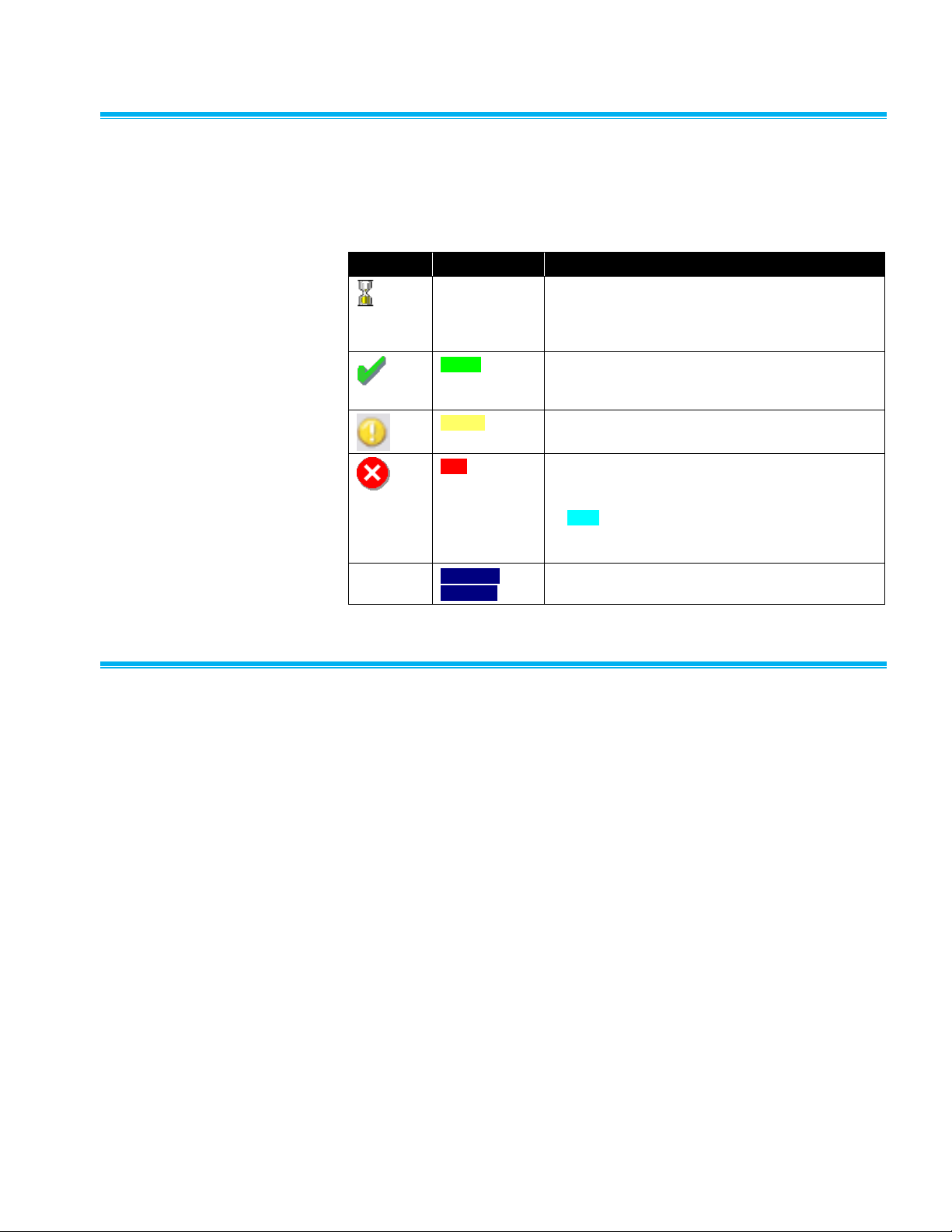
Color and Icon Codi n g
A color coding is used to show the alarm state of items on the system.
Usually an icon is displayed on the left-hand side to symbolize the alarm
state. The color coding is listed in the table below.
Icon
Text Color
Meaning
White
Indicates an idle state. This means that the system
is waiting for the first data to be received after
starting. This can also mean there is a problem if
an item remains white for a long period of time.
Green
Indicates an item is OK. The currently measured
values are not outside any alarm or warning limits
and any associated equipment has not failed.
Yellow
Indicates the item is in a warning state.
Red
Indicates the item is in an alarm state. Usually
when a sample point enters an alarm state, it
requires acknowledgement. The item will be shown
in cyan until the alarm is acknowledged. The icon
associated with the item changes to reflect the
current alarm state of the item.
D A R K
B L U E
Marks that an item has failed. Usually there will be
some Notes to indicate the reason for the failure.
Using the Client Displa y
The client display is divided into several parts:
1. A menu bar at the top.
2. A tool bar that offers most of the options of the menu.
3. A tab control that shows each detected monitoring system. The tab
headings show the current state of each node.
4. Tables of sample points and alarm groups on the last selected node.
The table cells are color coded to show the alarm state of the sample
points.
5. A list of units belonging to the currently selected node. The list is color
coded to show the alarm state of the unit.
6. A window display for a list of color-coded messages.
The monitoring nodes can be selected and viewed by clicking on the
appropriate tab. Please note: only one of these items can be viewed at any
one time.
Page 27

FMS Client 4–3
Menus
Client
Menu Item
Description
Login/Logout
Quickly login in and logout of the client.
Client Options
This item allows the local configuration for the client to be
set up.
Change Password
Allows the password of the current user to be changed.
The new password must be more than five characters, it
must also be the same in the New and Confirm password
fields before it can be accepted. The current password is
also required.
User Log
Allows general comments to be made into the event log to
record observations or comments. The currently logged in
username is added to the message.
E-mail
Opens a simple e-mail client to send short e-mail
messages to one of a restricted set of recipients. This is
intended as an alternative to the user log entry function
where users want to record general events or Notes.
E-mailing is enabled in the local Options.
Refresh
Updates the node list to reflect current connected nodes.
Nodes are only removed from the list if they have been
inactive for > 1 min.
Exit
This menu option is only enabled for users with Exit
privilege. When selected and confirmed, the client interface
is closed. This may cause an operating system level logout
or restart.
Node
Menu Item
Description
View
View Status, Maps, and Graphs associated with each
monitoring node.
Report
Access all functions related to report, including generating,
saving, and exporting reports.
Control
Gives access to control monitoring nodes, including unit
recipe, sample point recipe, and control of current node.
Configure
Gives access to configure each node.
Windows
Menu Item
Description
Units
Display the status of the units associated with the currently
selected node.
Statistics
Displays all the statistics associated with sample, tag,
alarm limits, SPC Status, and SPC limits.
Alarm Groups
Displays the status of the alarm groups.
Page 28
4–4 FMS Software User’s Manual
Help
Menu Item
Description
Help
Opens the on-line manual at the index page.
About FMS
Displays the client software copyright, version, and build
date information.
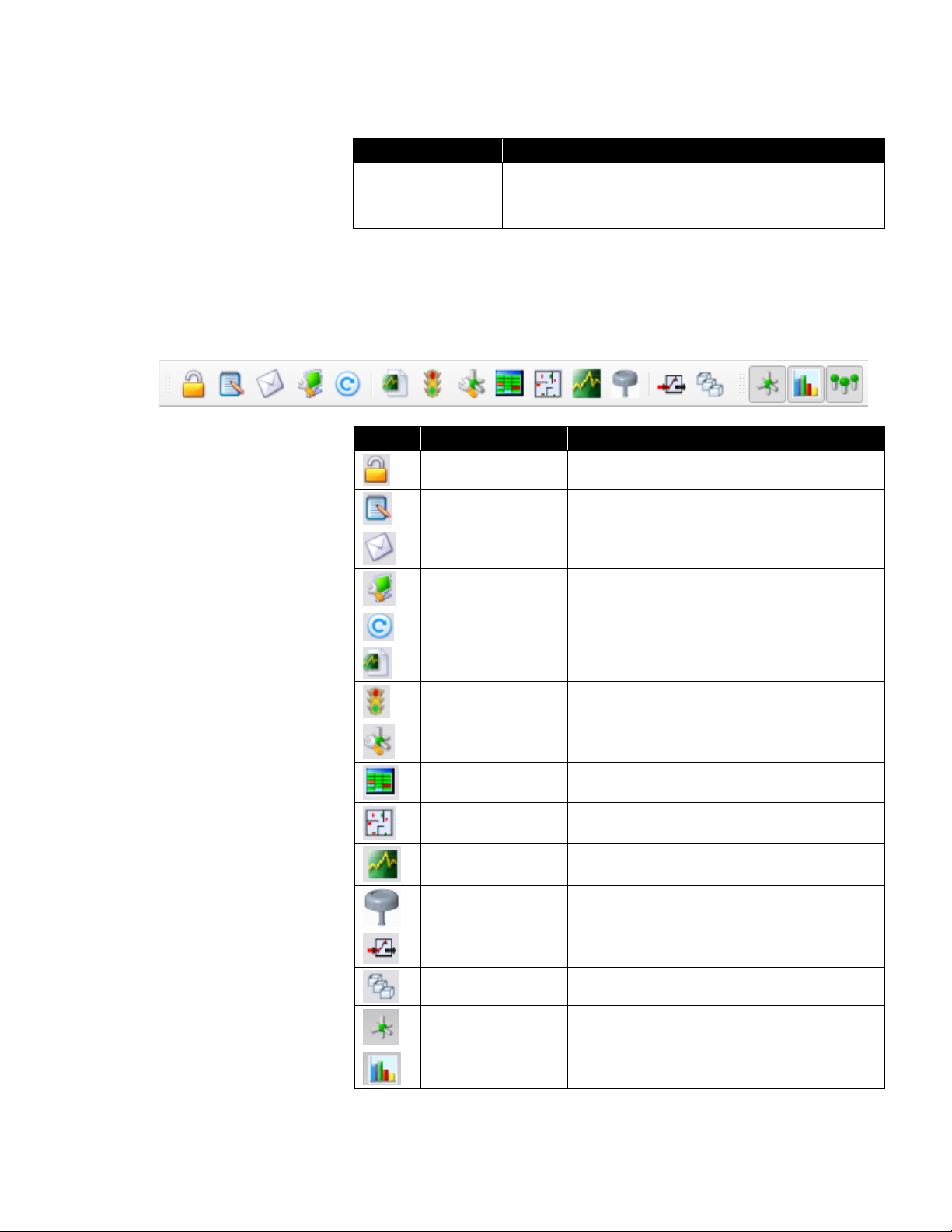
Toolbar
The toolbar options are similar to those given in the menu with the following
additions. Where the icon on the toolbar is the same as in the menu, the
function is the same.
Icon
Icon Name
Description
Login/Logout
Quickly login/out of Client.
User Log
Enter user log.
E-mail
Access e-mail functions.
Client Options
Configure client options.
Refresh
Refresh current status of the node.
Report
Set up and configure reports.
Control
Control each node.
Configuration
Configure each node.
View Status
View status view for each node.
View Map
View map view for each node.
View Graph
View graph view for each node.
View AAS Status
Show AAS status view for each node..
Output Control
View Digital Output Control for each node.
Batch Manager
View Batch Manager for each node.
View Units
View current status of all units connected to the
selected monitoring node.
View Statistics
View statistics of selected sample points.
Page 29
FMS Client 4–5
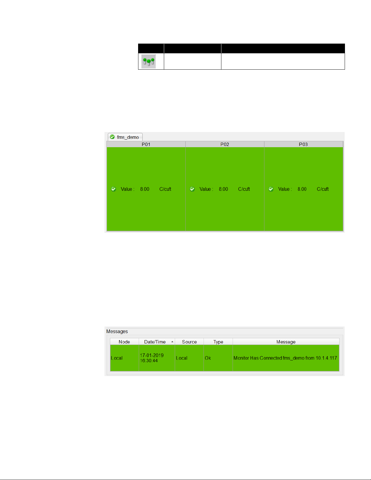
Icon
Icon Name
Description
View Alarm Group
View the alarm group status of current node.
Sample Status View
This pane shows all the sample points associated with the selected Node.
This list is color coded to show the current alarm state of the sample points.
The name, state, and current reading of each sample point are displayed.
Message
This pane displays the last 250 messages from all accessible nodes. The
messages are color coded for the type of message.
The Node column identifies the sample point node. Date/Time is the time
stamp for the message. The Source column identifies the origin of the
message—this can be a sample point, node, unit or some other item. The
Type is the alarm state of the message. The Message field the
message text.
Status Bar
The status bar shows the most recent message from the FMS software.
Page 30

4–6 FMS Software User’s Manual
Logging into FMS
Logging on to FMS
requires a valid
user account for the
FMS system being
used.
Each user for a particular FMS system has privileges to perform various
functions. Users can be assigned permission to change the configuration,
other users can be allowed to acknowledge alarms or make reports.
Password Aging
If password aging is enabled and after the given number of days have
elapsed, the user will be asked to change their password using the change
password dialog.
Configuring the Clie n t
To configure a client system, a valid username and password for the FMS
system in question must be used. To access the configuration facilities it is
necessary to log onto the computer. Select Client -> Client Options or click
the Client Options button on the tool bar.
Page 31

FMS Client 4–7
Identification
Client Name
Title used as the caption of the user interface.
License Key
License key issued. This controls the number of sample
points that can be accessed. When a license expires, a
reminder is displayed. If more than one client tries to use
the same license key, these clients are disabled. License
keys are FMS minor version specific. i.e., a license key
that was generated for FMS 5.2.0 will only work with FMS
5.2.x systems. License keys that were generated prior to
FMS 5.2.0’s release are valid for all FMS 5.0.x versions
and FMS 5.1.x.
Broadcast Port
The port to be used for Client broadcasts.
Broadcast Using
The network interface to be used for Client broadcasts.
Multicast IP
Address
The IP address to be used for multicast network.
Multicast Port
The port to be used for multicast network.
Page 32

4–8 FMS Software User’s Manual
Audit Logging
This option configures the node that Audit log messages will be logged in
and the text to be displayed as the source of audit log entries originating
from the Client. If users are required to enter comments when changing
configuration, the option exists in the Node security settings.
Page 33

FMS Client 4–9
Modules
This page selects which of the loadable extension modules are to be used
by the client. This feature is used to enable or disable blocks of features.
Page 34

4–10 FMS Software User’s Manual
FMS Components Information
This page displays a printable table of the version numbers and builds dates
of the components of the FMS software.
(screen for reference only)
Page 35

FMS Client 4–11
Remote Monitors
This page allows the user to define remote monitoring tasks not on the local
network that the Client is to connect to. The IP address and request port of
the remote monitor must be specified.
Page 36
4–12 FMS Software User’s Manual
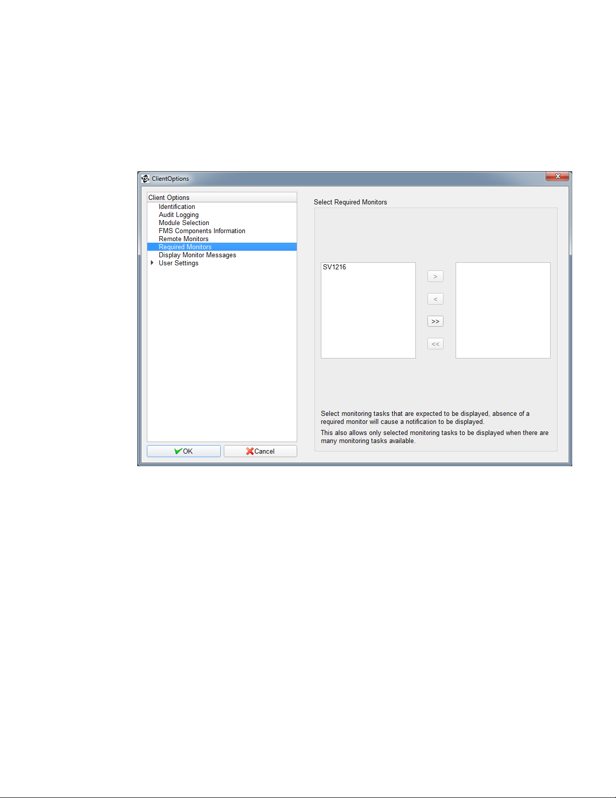
Required Monitors
This page allows the user to define monitoring tasks that are to be displayed
by this Client. If a required monitor is not present, a failure condition will be
triggered.
If no required monitors are specified, all detected monitors will be displayed.
Page 37

FMS Client 4–13
Display Monitor Messages
The messages window will display messages from the Monitors that are
checked in this window. By default, all Monitors are checked.
Page 38

4–14 FMS Software User’s Manual
User Settings
This page selects the Language option and the Date Format option. The
Font Type and Size options can be selected for the main application and for
the status tables.
Page 39

FMS Client 4–15
Color Settings
This page configures the colors associated with each state of the sample
points. Alarm recovery messages are by default shown as Alarm
notifications, select the option Show recovery messages as Ok to show
these message types as OK in the Messages window.
Page 40

4–16 FMS Software User’s Manual
Sound Settings
This page configures the sounds played on a local computer when a node is
not in an OK state. The sound played is that for the highest alarm state of all
the detected monitoring systems. Select a sound to play and set the
corresponding checkbox. Click the Play button on the far right of the
filename to test a sound. Sounds are played about every 10 seconds. For
this reason any sound should be less than 10 seconds in duration.
Page 41

FMS Client 4–17
Auto Login Settings
This page sets the auto login username and password for the Client and the
preferred node to be displayed on startup.
Page 42
4–18 FMS Software User’s Manual
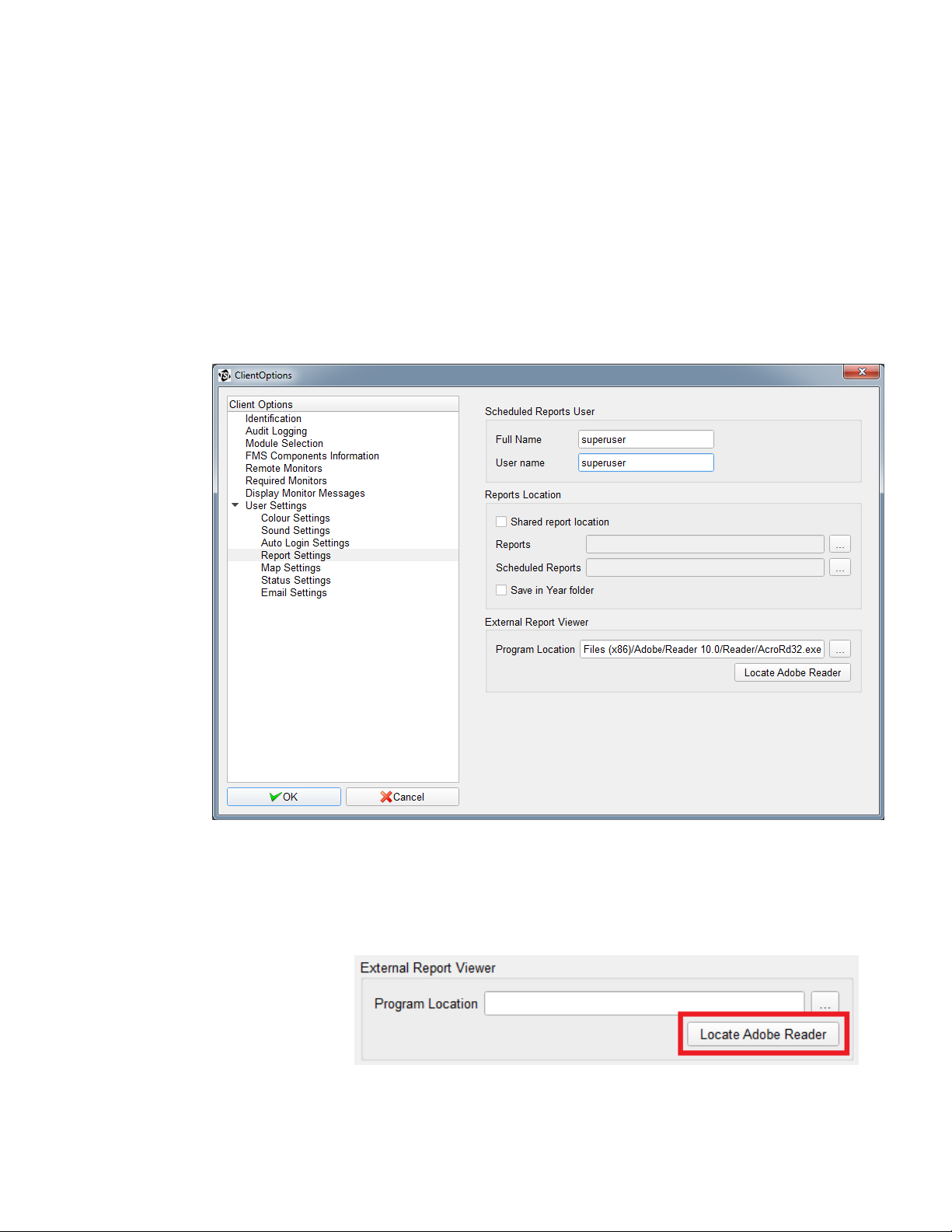
Report Settings
This page sets the scheduled report username. Scheduled reports will be
generated according to the set schedule.
This page also sets the location where generated reports will be saved. If
Shared report location is checked, reports generated by all users will be
saved in the folders specified in the Reports and Scheduled Reports fields. If
not checked, reports will be saved for each user in the Users folder.
Selecting the option Save in Year folder will result in reports being saved in
sub-folders named according to the year the report is created in e.g., “2012”.
In addition, this page also configures viewing a report in an external PDF
viewer such as Adobe® Reader®.
The “Locate Adobe Reader” button will attempt to automatically locate the
installed Adobe Reader software.
Page 43

FMS Client 4–19
If the “Locate Adobe Reader” fails to find Adobe® Reader®, or you want to
use a different program, select the “…” button which will open a file browser,
and browse to the executable file of the program that you want to open
PDF reports.
After selecting Open, the text field will automatically populate with the
selected file path.
Page 44

4–20 FMS Software User’s Manual
Map Settings
This page sets the map options that will be used for the map display for
this Client.
Page 45
FMS Client 4–21
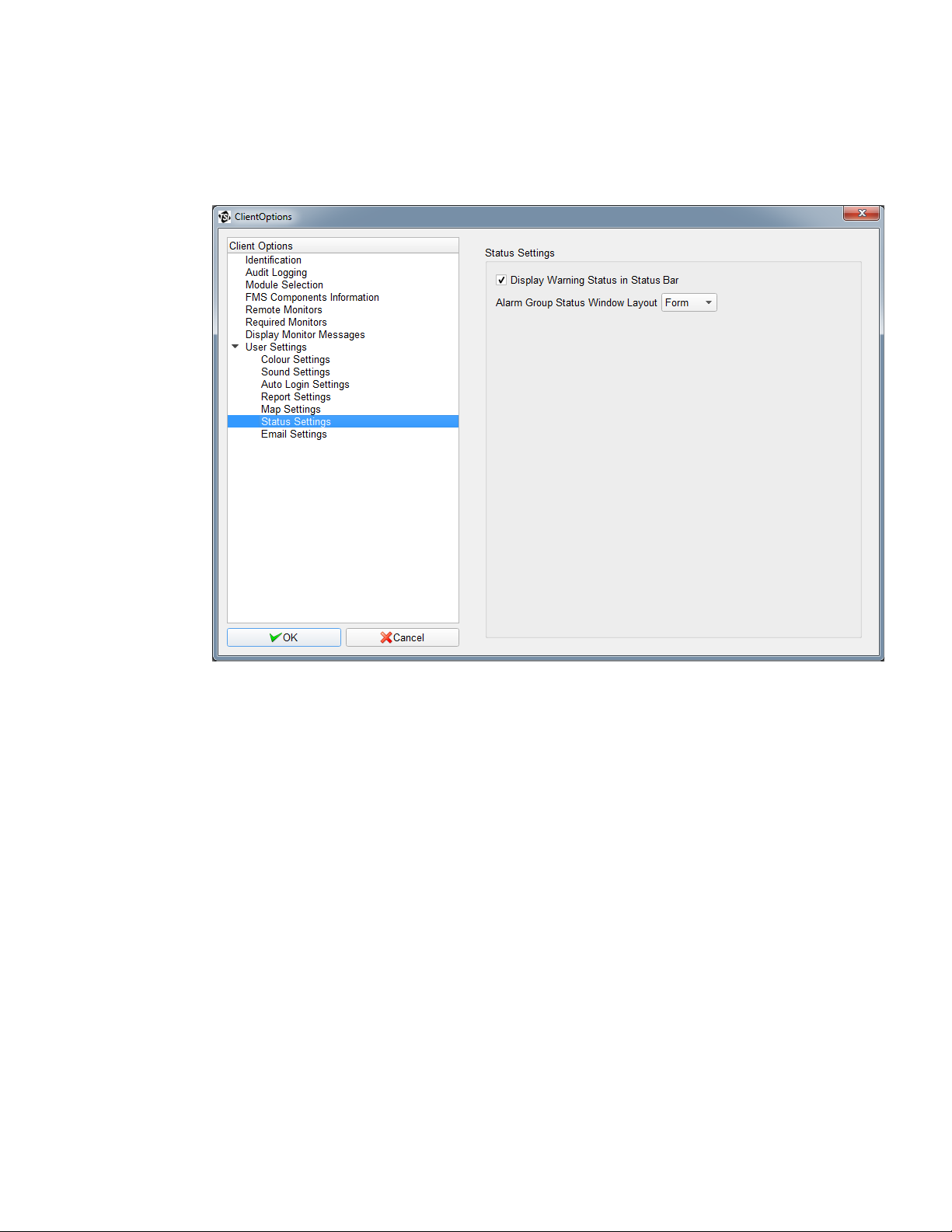
Status Settings
It is possible to configure Status Settings so warning messages are not
displayed in the Status Bar.
Page 46
4–22 FMS Software User’s Manual
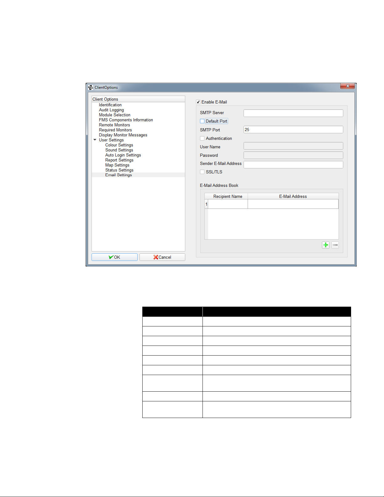
E-mail Settings
It is possible to configure E-mail Outputs such that an e-mail is sent when an
alarm group enters a particular state, for example if it starts alarming.
This page sets the e-mail SMTP server, the e-mail address of sender, and
the list of e-mail recipients. The E-mail Output configuration options are
as follows:
E-mail Option
Description
SMTP Server Name
Address of the server which will handle the e-mail.
Default Port
Use the default port for the SMTP Server.
SMTP Port
The port to use for the SMTP Server.
Authentication
Enable authentication for e-mail.
User Name
The user name to use to authenticate the e-mail.
Password
The user password to use to authenticate the e-mail.
Sender’s E-mail
Address
Originator's e-mail address used to identify where the
e-mail came from.
SSL/TLS
Enable SSL/TLS..
Recipient E-mail
Address Book
Permitted e-mail addresses to which e-mail alerts can
be sent.
Page 47
5-1
C H A P T E R 5
Using FMS Client
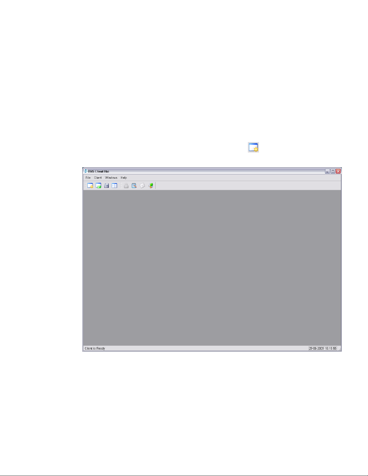
FMS 5 allows software installation in standard mode. In this mode, the client
will be very flexible. Multiple status, graph, and report windows can be
created. Multiple map windows to monitor the status of sample points can
also be created. FMS software also allows current settings to be saved and
loaded later. Use File -> New or click the button to create a new window
after the FMS software starts.
NOTE: This option is not available in Pharma mode.
Page 48

5–2 FMS Software User’s Manual
Create Status Window
To create a new Status window, use File -> New or click on the button.
Select Status from the Window Type list then select the node for which the
status will be displayed. Click Next.
Page 49

Using FMS Client 5–3
In Table format, status will be displayed as table shown below. Alarm groups
can be included in Table format.
In List format, status will be displayed as list shown below. The list can be
sorted by data types. Alarm groups cannot be included in List format.
Page 50

5–4 FMS Software User’s Manual
Then the sample points to be shown on the Status window should be
selected. Click Next to go to the next step.
An optional “Additional Title Text” can be added to identify each Status
Window. Multiple Status windows can be created and displayed at the
same time.
Page 51

Using FMS Client 5–5
Create Units Window
To create a new Units window, use File -> New or click on the button.
Select Units from the Window Type list then select the node for which the
units will be displayed. Click Next.
An optional “Additional Title Text” can be added to identify each Units
Window. Multiple Units windows can be created and displayed at the
same time.
Page 52
5–6 FMS Software User’s Manual
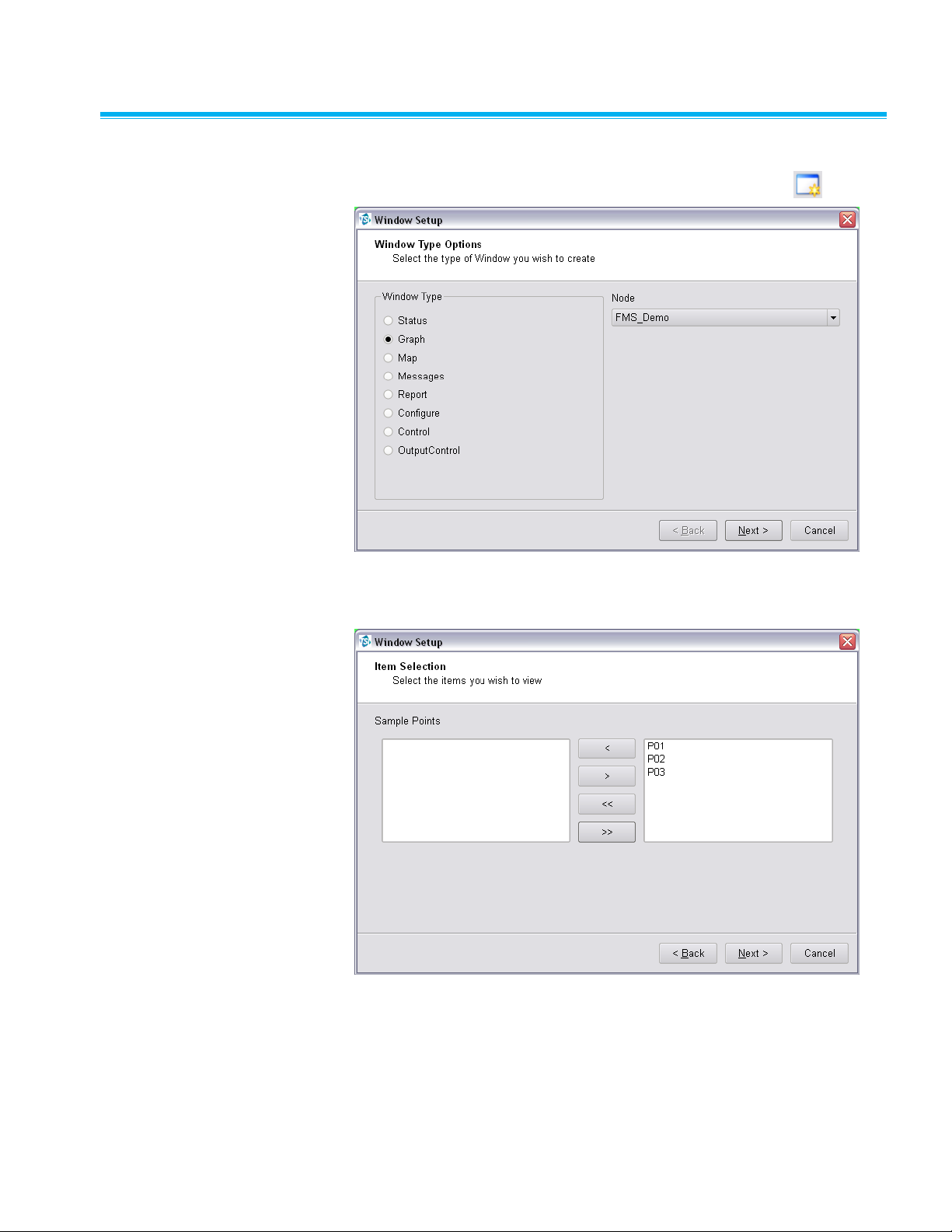
Create Graph Window
To create a new Graph window, use File -> New or click on the button.
Select Graph from the Window Type list then select the node for which the
graph will be displayed. Click Next.
Page 53

Using FMS Client 5–7
Now the sample points to be shown on the Graph window should be
selected. Click Next to go to the next step.
Graph options allow selection of the start and end time for graph display. It
also allows configuring the graph as dynamic or using log scales, static or
dynamic rolling graph. A dynamic rolling graph will maintain the previous
amount of specified time on the graph. For example, a 1-hour dynamic
rolling graph will maintain the previous 1 hour of data on the graph relative to
the current time.
Page 54

5–8 FMS Software User’s Manual
A graph can also be initially created with certain channels and limit lines
enabled or disabled. By default all channels and limit lines are enabled. If a
channel is disabled, all associated limit lines will automatically be disabled
as well.
An optional “Additional Title Text” can be entered to help identify the
graph display.
Page 55

Using FMS Client 5–9
Create Message Window
To create a new Message window, use File -> New or click on the
button. It is only possible to open one Message window at any time.
Select Messages from the Window Type list. Click Next.
An optional “Additional Title Text” can be added to identify the
Messages Window.
Page 56

5–10 FMS Software User’s Manual
Create Map Window
To create a new Map window, use File -> New or click on the button.
Select Map from the Window Type list then select the node for which the
map will be displayed. Click Next.
An optional “Additional Title Text” can be added to identify each Map
window. Multiple Map windows can be created and displayed at the
same time.
Page 57

Using FMS Client 5–11
Create Report Window
To create a new Report window, use File -> New or click on the button.
Select Report from the Window Type list then select the node for which the
report will be displayed. Click Next.
An optional “Additional Title Text” can be added to identify each Report
window. Multiple Report windows can be created and displayed at the
same time.
Page 58

5–12 FMS Software User’s Manual
Create Configure Window
To create a new Configure window, use File -> New or click on the
button. It is only possible to open one Configure window at any time.
Select Configure from the Window Type list then select the node for which
the configuration will be displayed. Click Next.
An optional “Additional Title Text” can be added to identify the
Configure Window.
Page 59

Using FMS Client 5–13
Create Control Window
To create a new Control window, use File -> New or click on the button.
Select Control from the Window Type list then select the node for which the
controls will be displayed. Click Next.
An optional “Additional Title Text” can be added to identify the
Control window.
Page 60
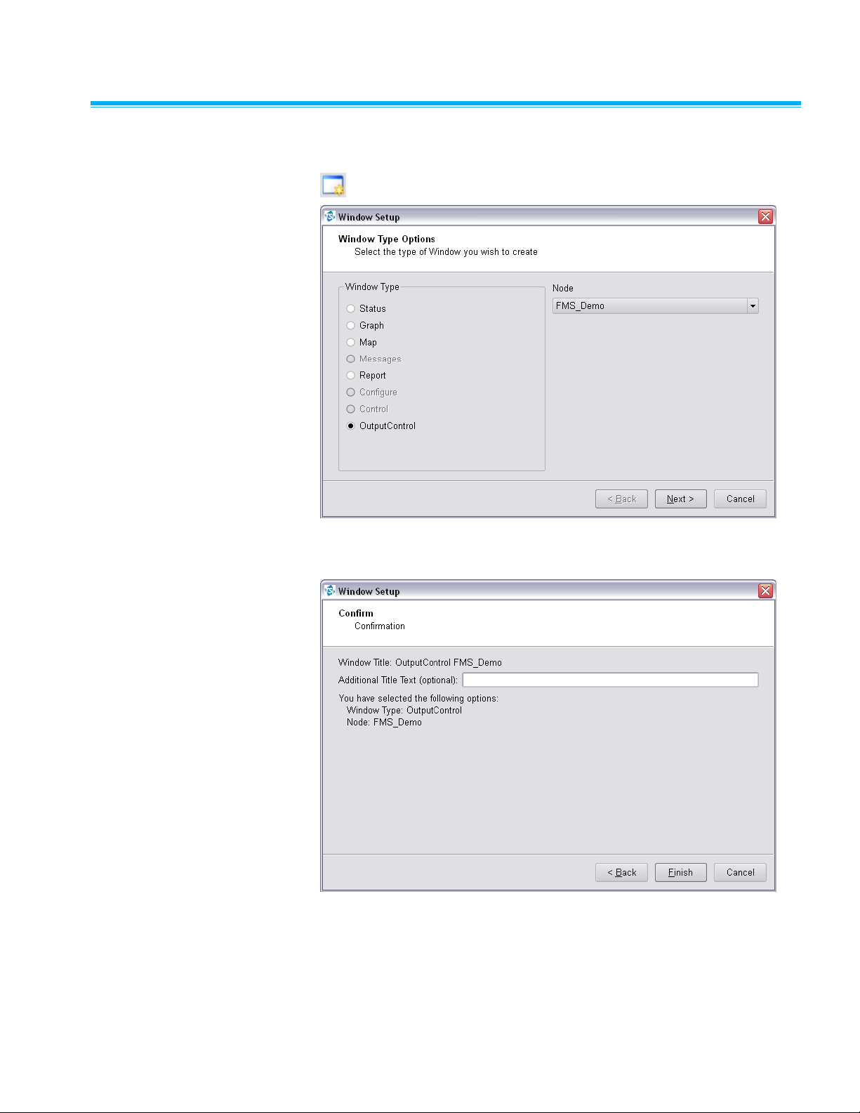
5–14 FMS Software User’s Manual
Create Output C ontrol Window
To create a new Output Control window, use File -> New or click on the
button.
Select Output Control from the Window Type list then select the node for
which the output controls will be displayed. Click Next.
An optional “Additional Title Text” can be added to identify the Output
Control window.
Page 61
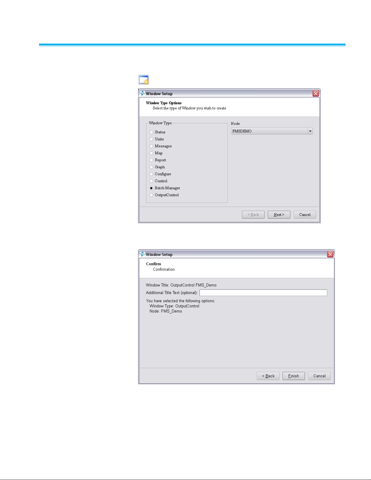
Using FMS Client 5–15
Create Batch Manager W i n d o w
To create a new Batch Manager window, use File -> New or click on the
button.
Select Batch Manager from the Window Type list then select the node for
which the output controls will be displayed. Click Next.
An optional “Additional Title Text” can be added to identify the
Control window.
Page 62

5–16 FMS Software User’s Manual
(This page intentionally left blank)
Page 63

6-1
C H A P T E R 6
Configure and
View Monitoring Node
To configure a monitoring system the user must have a valid username and
password for the node in question and have permission to configure that
node. To access the configuration facilities it is necessary to log into the
node and select the Node -> Configure menu option.
Configure Node
Only users with appropriate permissions can configure the FMS system for
the node to be configured. It is possible for different clients to try and edit a
given monitoring system's node at the same time. For this reason, it is
preferable to have only one user with configure permission per
monitoring system.
To configure a particular monitoring system, select the monitoring system in
the node tab and select Node -> Configure from the menu; or select the
node in the node tab and click on the button on the tool bar.
Page 64

6–2 FMS Software User’s Manual
Monitor Details Page
This page displays the current settings of the monitor. The current
configuration can be exported to a file. Connected Ethernet-to-Serial
converters can also be searched for.
Monitor Summary -> Configure Devices
This page displays the current configured units, sample points and
digital outputs.
Page 65

Configure and View Monitoring Node 6–3
Monitor Summary -> Configure Devices -> AeroTrak+ Devices
This page manages the AeroTrak®+ device configurations. If configuring an
AeroTrak®+ Remote Particle Counter please follow technical note TCC-165.
If configuring an AeroTrak®+ Active Air Sampler please follow technical note
TCC-187.
Monitor Summary -> Configure Devices -> Communication
FMS uses Communication Channels to communicate with equipment. There
are two types of communication channel Ethernet using TCP/IP and serial
port. Usually the Ethernet communication is to an Ethernet-to-serialconverter.
This page displays the current configured communication interfaces. An
existing communication interface can be configured or create a new
communication interface. To configure an existing interface, right mouse
Page 66

6–4 FMS Software User’s Manual
click on the selected communication and select Properties from the
pop-up menu.
To create a new communication, right mouse click on the blank area, select
New Communication Channel from the pop-up menu.
Field
Description
Name
Free text description of the channel.
Packet Driver
Enables selection of the preferred packet driver mode.
Ethernet Communications
In the case of Ethernet serial ports the port configuration is done using a
Web Browser or Telnet interface. Ethernet devices have the advantage in
that they can be independent of the computer the monitoring task is running.
Field
Description
IP Address
IP address of the unit. This will often be a fixed IP address
but can be a host name (e.g., serial factory) if DHCP is
used to set up network addresses.
IMPORTANT: Do not use any leading zeroes in the IP
Address as this will not work with FMS, i.e., do not use
192.168.044.56, instead use 192.168.44.56.
Port Number
TCP port to connect to. Refer to the Ethernet device's
documentation for full details.
Page 67

Configure and View Monitoring Node 6–5
Serial Communications
This sets up the serial ports for the computer on which the monitoring
system is running.
Item
Description
Name
Selects the serial port to use.
Packet Driver
Enables selection of the preferred packet driver mode.
Baud Rate
Selects the speed at which the interface is to run.
Data
Number of data bits in the serial byte. Usually this is 8.
Stop
Number of stop bits. This is usually 1.
Parity
Selects the parity bit. This is usually None.
Flow Control
Selects the type of flow control used for controlling data
transmission. Usually this is None, but can be Hardware
(for RTS/CTS/DTR) or Xon/Xoff.
Page 68
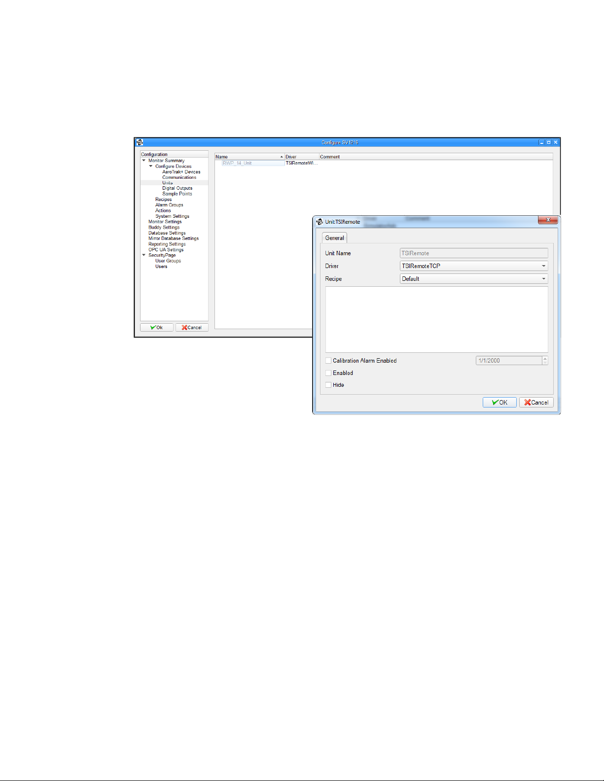
6–6 FMS Software User’s Manual
Monitor Summary -> Configure Devices -> Units
This page displays the current configured Units. An existing Unit can be
configured or a new Unit created. To configure an existing Unit, right mouse
click on the selected Unit and select Properties from the pop-up menu.
To create a new Unit, right mouse click on the blank area, select New Unit
from the pop-up menu.
Page 69

Configure and View Monitoring Node 6–7
Monitor Summary -> Configure Devices -> Digital Outputs
A Digital Output is an abstraction of an output from a unit that can be on or
off. Relay outputs, that in turn control alarm beacons, is a common example.
This page displays the current configured digital output. An existing Digital
Output can be configured or a new Digital Output created. To configure an
existing Digital Output, right mouse click on the selected Digital Output, and
select Properties from the pop-up menu.
To create a new
digital output, right
mouse click on the
blank area, select
New Digital Output
from the pop-up
menu.
The Digital Output
forms allow
mapping an alarm
group to a selected
unit's digital output.
The device driver
for the unit supplies
the list of possible
digital outputs.
Page 70

6–8 FMS Software User’s Manual
The recipe independent part of the digital output configuration has the
following fields:
Field
Description
Alarm Group
Selects the alarm group that controls the digital output.
Alarm State
Sets the test used to determine if a digital output is on or
off. An output is on if the expression is true; otherwise, it is
off. The first field is a comparison operator (<,>, =, <>), the
second field is the alarm level to compare against. The
resulting expression, <alarmgroup state> <comparison
operator > <alarm level> is evaluated every time the
alarm group is updated, and the digital output updated
according to the result.
Allow Control and
Scheduling
When set the digital output can be controlled and
scheduled from the Client.
Enabled
When set the output is active and the output follows the
configured relationship with the alarm group. If not, it
remains at the default state.
Retrigger
When set the Digital Output will force the output to refresh
even if no changes have occurred. This is useful where
manual silencing of alarms may be used.
Monitor Summary -> Configure Devices -> Sample Points
Sample Points represent measured values from units.
This page displays the current configured Sample Points. An existing
Sample Point can be configured or a new Sample Point created. To
configure an existing Sample Point, right mouse click on the selected
Sample Point and select Properties from the pop-up menu.
Page 71

Configure and View Monitoring Node 6–9
Field
Description
Sample Point Name
Free text description of the sample point.
Unit
Unit associated with the sample point.
Data Type
Identifies the class of measurement. Units can often
measure several types of data; for example, particle
counts, environmental parameters, and instrument status.
Display Units
Free text field that allows the physical units to be set for
display purposes.
Input Index
Selects the channel of a particular sample point type that
is mapped to the sample point. Only the available input
indices are given as choices.
Decimal Places
Selects decimal places for displaying the sample points.
Recipe
The recipe for which sample point properties are
displayed.
Comments
Free text that will be displayed with the sample point name
in reports and Inspect windows.
Additional
Comments
Free text that will be displayed with the sample point name
in reports.
Use Log Graph
Scales
When set, graphical displays will use log scales when
displaying any data from this sample point. Usually this is
set when the data is from particle counters where the
range of values is very large.
Calculate MKT
Select if the option to calculate mean kinetic temperature
for reports, is required for a sample point.
Page 72

6–10 FMS Software User’s Manual
The SPC tab specifies the SPC alarm limits and the control limits. The Alarm
limit and Mean Crowding limit only have effect if valid control limits are
defined. SPC alarms are not always appropriate.
The Recipe tab allows selection of the Preferred Tag which is a hint for
some displays to show values for this tag before others.
Page 73

Configure and View Monitoring Node 6–11
Field
Description
Enabled
When checked, the sample point is enabled and data
collected for the sample point is updated and processed. If
a sample point is not enabled, data will still be collected for
it, but not updated or processed.
Fileable
When checked, the collected data is stored in the
database, providing the sample point is also enabled. This
is usually checked. However, there are cases where
measured data is only for information or diagnostic
purposes and not required as a part of any permanent
record.
Re-triggerable
Alarms
When checked, an alarm event is generated for each
measurement that is in alarm. When it is clear, an alarm
event is generated only when a sample point enters an
alarm state. This affects the setting of the acknowledgment
required flag. If this flag is set, the acknowledgment
required flag gets set with each value in an alarm state.
Hide
When checked, the sample point will not be displayed in
Status displays.
Disable
Acknowledge
When checked, the alarm start will not be
acknowledgeable.
Alarm Threshold
Number of consecutive values that are outside the alarm
limits that must be measured before the sample point goes
in to alarm. Until the alarm threshold is exceeded, the
sample point is put into a warning state. This feature is
useful for measurements which can have brief periods of
being in alarm in normal use (such as differential pressure
sensors) and so these nuisance alarms can be
suppressed.
Sample Period
Sets the sample period in number of seconds. This field is
only enabled when relevant.
Preferred Tag
Sets the preferred tag for the sample point.
Enable Buffer
Download
When checked, FMS will perform buffer download as
needed for the unit related to the sample points. Buffer
size will define data points read from unit buffer.
Page 74

6–12 FMS Software User’s Manual
Field
Description
Alarm Limits
Table of alarm and warning thresholds for each of the
possible sample point values tags. To enable a warning or
alarm threshold, set the check to the right of the limit and
then enter the threshold value.
The Driver tab allows selection of options that are specific to the type of Unit
for the sample point.
The Driver Recipe tab allows selection of options that are specific to the
type of Unit for the sample point and that can vary dependent on which
Recipe is in use.
Page 75
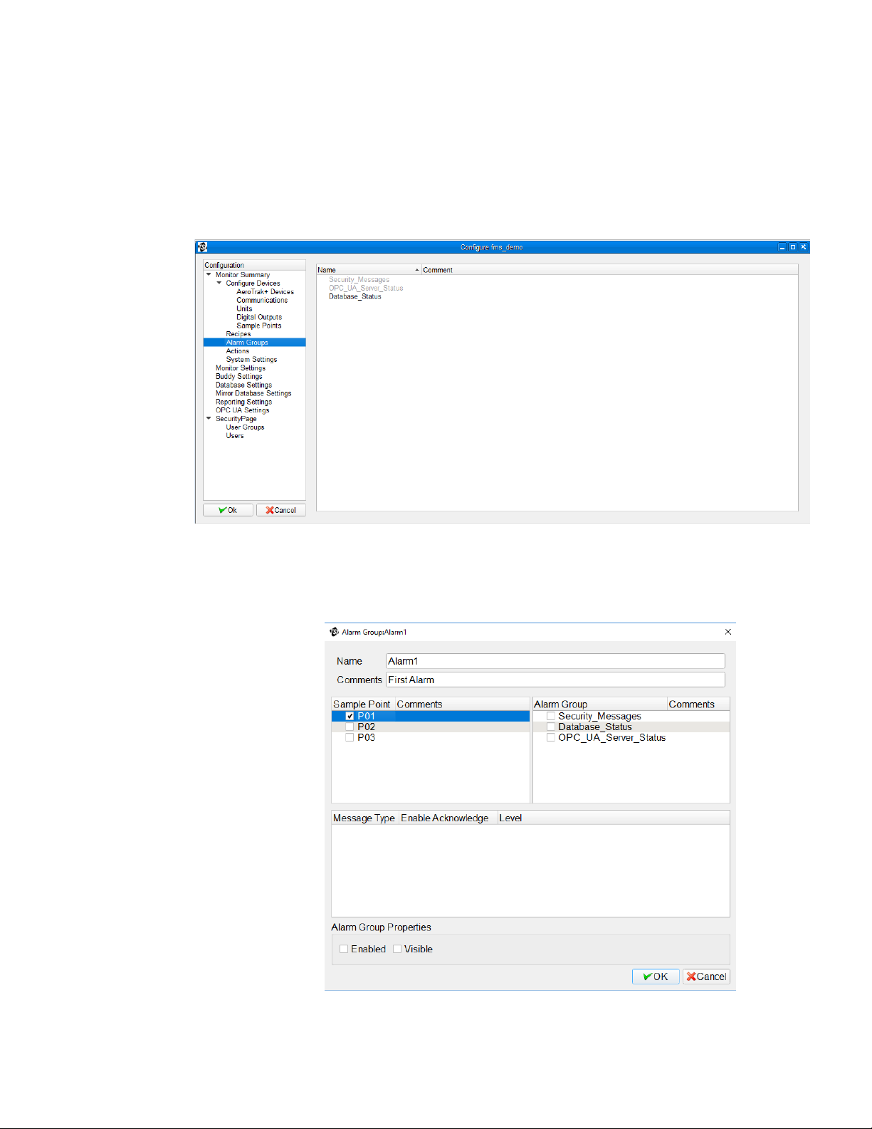
Configure and View Monitoring Node 6–13
Monitor Summary -> Configure Devices -> Alarm Groups
Alarm groups are collections of sample points and other alarm groups. The
alarm state of an alarm group is the highest alarm state of any of the
members. Alarm groups are useful for managing alarm enunciation and
controlling events.
This dialog displays the current set alarm groups. An existing alarm group
can be configured or create a new alarm group. To configure an existing
alarm, right mouse click on the selected alarm, and then select the
properties option from the pop-up menu.
Page 76

6–14 FMS Software User’s Manual
Use this screen to choose to enable or disable an alarm group. To create a
new alarm group, right mouse click on the blank area and then select
New Alarm Group from the pop-up menu.
Alarm Groups have the following recipe independent parts:
Part
Description
Comments
A free text description of the alarm group that appears in
the alarm group display.
Sample Point List
Lists all sample points for the monitoring node. To include
a sample point in the alarm group set the checkbox next to
it. To remove a sample point from the alarm group clear
the checkbox. Any one sample point can belong to any
number of alarm groups.
Alarm Group List
A list of all alarm groups at the monitoring node. To include
another alarm group in an alarm group, set the check next
to it. To remove the alarm group, clear the check next to it.
An alarm group can belong to any number of other alarm
groups on the same node. It should be noted that cyclic
dependencies (where an include alarm group depends on
the alarm group that it is being included in) are not
detected and although this will not cause any failures, the
alarm group will remain at whatever the highest alarm state
becomes.
Message Type
List of messages associated with the driver type of the
selected Sample Point.
Enable
Acknowledge
Require acknowledgement of the corresponding driver
message.
Enable
This checkbox is recipe dependent. So it is possible to
have alarm groups active only when certain recipes are
enabled globally.
Visible
When this checkbox is set, the alarm group will appear on
the Alarm Group Status display. This is a hint to other
modules that the alarm group can be displayed.
Page 77

Configure and View Monitoring Node 6–15
Monitor Summary -> Configure Devices -> Recipes
This page displays the current configured Recipes. An existing Recipe can
be configured or a new Recipe created. To configure an existing Recipe,
right mouse click on the selected Unit and select Properties from the
pop-up menu.
Monitor Summary -> Configure Devices -> Actions
An Action is a task that is triggered by either a timed event or a change of
sample point state.
Page 78

6–16 FMS Software User’s Manual
This page displays the current configured Actions. An existing Action can be
configured or a new action created. To configure an existing Action, right
mouse click on the selected Action and select Properties from the
pop-up menu.
State Trigger Action
Page 79

Configure and View Monitoring Node 6–17
Timed Trigger Action
Field
Description
Name
The name of the action.
Sample points
(State trigger only)
The Sample Points that can trigger the action.
Trigger
(State trigger only)
The sample point event that will trigger the action. Options
are Alarm or (value) Update.
Scheduled time
(Timed trigger only)
The time at which the action is to be executed.
Notes
Free text field for configuration notes.
Log when triggered
When checked, the action will be logged in the event log
when triggered.
Enabled
When checked the Action is enabled and can be triggered.
Action
The command to be run when the action is triggered, e.g.,
notepad.exe "C:\FMS5\Actions\Alarm.txt".
Substitute values
When checked fields in the Action will be replaced by
actual values when the Action is triggered.
?
Select to see a table of options available for command line
substitution.
Action command line substitution options
Page 80

6–18 FMS Software User’s Manual
Monitor Summary-> Configure Devices -> System Settings
This page allows setting general system settings.
Field
Description
Reset at Midnight
When selected the statistics displayed in statistics
windows will be zeroed at midnight.
Acknowledgement
Reasons
Enter a set of standard reasons that can be selected when
acknowledging alarms.
Page 81

Configure and View Monitoring Node 6–19
Monitor Settings
This page allows setting general settings related to the monitor.
Field
Description
Monitor
Identification
Allows entering the name of the monitor node and the
license key associated with the monitor node.
Monitor Language
Settings
Allows configuring the language option of the monitor and
text read orientation of the monitor.
Monitor Traffic
Settings
Sets the port number to be used by the client and
monitoring systems to broadcast messages to all other
monitoring systems and clients. This must be the same for
all members of a networked monitoring system; otherwise,
not all members of the monitoring network will be detected.
It is possible to have more than one network of monitoring
systems sharing the same LAN, using different broadcast
addresses to operate completely separate from one
another. Where no hardware supporting UDP broadcasts
are available, both the client and monitoring system must
be started with the local flag.
General
Allows setting a scheduled reboot time for the monitor and
SQL archive option.
Page 82

6–20 FMS Software User’s Manual
Buddy Settings
This page is used to set up a buddy system. A monitor can “watch” up to
three monitoring nodes and start a buddy monitor in case of failure of any of
the watched nodes. For each monitor that is being watched, the command
line to be used to start the buddy when a monitor fails must be specified.
The Buddy Behavior field Take Over After must be populated only for the
watching monitor to monitor how long a watched node must be inactive
before the buddy command line is executed.
The Buddy Behavior field Exit if Node Active must be populated only for the
buddy to specify the conditions that will cause it to exit. It must not be
populated for the watching monitor.
Page 83

Configure and View Monitoring Node 6–21
Database
This page sets database configurations.
Field
Description
Database Type
Sets the type of database used by the monitor.
Server Address
and Port
Sets the server address and port for the database.
Database Name
Sets the name of the database used by the monitor.
Test Connection
Allows testing database connection based on current settings.
Client User and
Password
Sets the Client username and password for database access.
Users must have read and write permissions.
Node User and
Password
Sets the node username and password for database access.
Users must have read, write, and create permissions.
Mirror Database
This page sets the mirror database setting for the monitor node.
Page 84
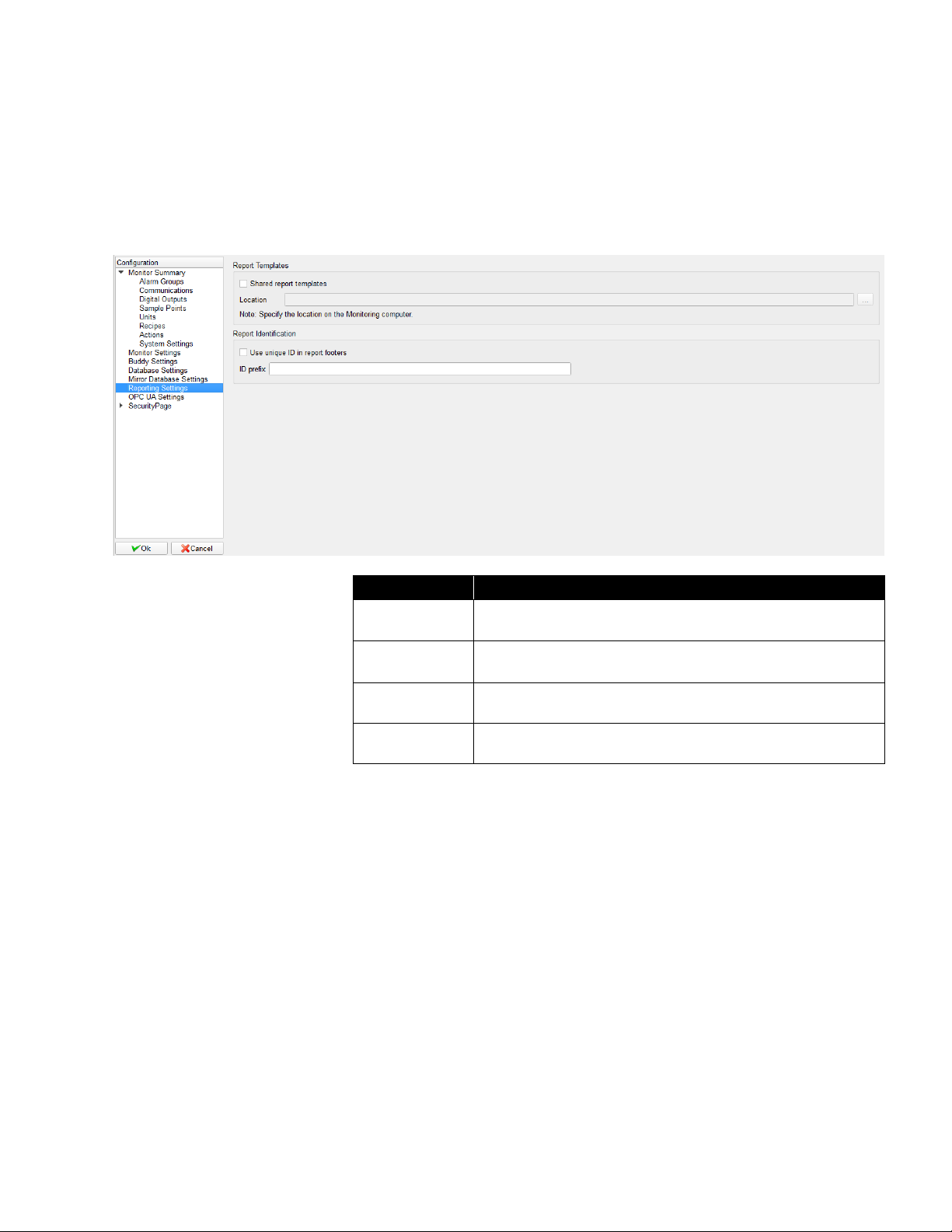
6–22 FMS Software User’s Manual
Reporting Settings
This page sets the report setting for the monitor node.
This page is used to determine whether all users share the same set of
report templates or if each user has access only to the reports that the user
has configured.
Field
Description
Shared report
templates
Select this option if all users are to share report templates.
Location
The location on the monitoring computer where the report
templates are to be held.
Use unique ID
Select if a unique 6 digit ID is to be displayed in the report
footer for each generated report. IDs are sequential.
ID prefix
Specify a prefix to precede the ID if required.
Page 85

Configure and View Monitoring Node 6–23
OPC UA Settings
This page is used to change OPC UA Server settings. Please follow
technical note, TCC-156 for configuring the OPC UA Server in FMS.
Security Page
This page sets the security related options.
Page 86

6–24 FMS Software User’s Manual
Field
Description
Enable As
Password Server
Enables the monitor to be the password server.
Comments required
for changes
When checked, comments are required to be entered
when changes are made to the configuration.
Maximum Idle Time
Client will automatically log the user out of the client
application when no keyboard or mouse activity has been
detected for the given number of minutes.
Password Duration
When checked, all passwords are required to be changed
if they are older than the given number of days. This is a
useful security feature as it prevents discovered
passwords being used for too long. However, if passwords
have to be changed too often, users can use simple
formulae to set their passwords or switch between two or
three favorites. This also sets if the last password is
allowed.
Failed User logins
allowed
Sets maximum attempts for user login. The Client will be
locked after the maximum failed attempts have been
reached.
NOTE: If Failed Client logins allowed is enabled, failed
User logins allowed must be less than failed
Client logins allowed.
Failed Client logins
allowed
Sets maximum attempts for Client login. The Client will be
locked after the maximum failed attempts have been
reached.
NOTE: If Failed User logins allowed is enabled, failed
Client logins allowed must be greater than failed
User logins allowed.
Unlock Client
Becomes enabled if a user attempts to login and fails for
the given number of times causing the client interface to
lock. The system administrator is required to unlock it.
Page 87

Configure and View Monitoring Node 6–25
User Group
This page displays the current configured User Groups. The table contains
an overview of each User Group’s parent category. The User Group will
have full privilege if the column displays “Yes” and no privilege if the column
displays “No”. If the column displays “Partial”, check the User Group’s
properties to see which sub-categories the User Group has access to.
An existing User Group can be configured or a new User Group created. To
configure an existing User Group, right mouse click on the selected User
Group and select Properties from the pop-up menu. To create a new User
Group, right mouse click on the blank area and select New User Group from
the pop-up menu.
Page 88

6–26 FMS Software User’s Manual
User Privileges
This is the initial window
when configuring a User
Group, the list of
categories are the parent
categories. A check
indicates the User Group
has full privileges to the
parent category and all
sub-categories, no check
indicates the User Group
has no privilege to the
parent or any
sub-category. If the check
box is partially checked
(Reports in the graph)
means at least one but
not all sub-categories are
checked.
When the mouse is hovered over a category, the text will be bolded and font
size slightly increased if the category has a sub-category. Click the text to
display the sub-category. This applies to parent categories as well as
sub-categories (some sub-categories have sub-categories).
Page 89

Configure and View Monitoring Node 6–27
Before any actions are taken, FMS will request a username and password
and will check if the user is allowed to perform the action before proceeding.
Page 90
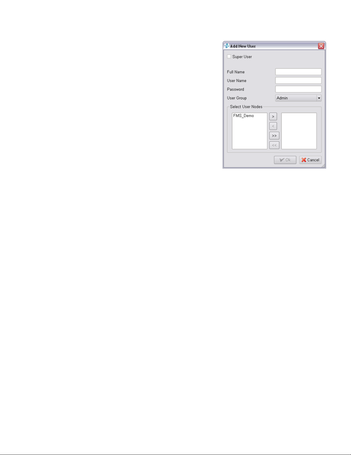
6–28 FMS Software User’s Manual
This page displays the
current configured Users. An
existing User can be
configured or a new User
created.
To configure an existing
User, right mouse click on
the selected User and select
Properties from the pop-up
menu.
To create a new User, right
mouse click on the blank
area and select New User
from the pop-up menu.
Page 91

Configure and View Monitoring Node 6–29
Viewing a Monit o r ing Node
To view a particular monitoring system, select the node in the tab controls.
The software will display all the samples points, alarm group, and statistics
associated with the node. View -> Status, Map, Graph and AAS Status can
also be selected.
Page 92

6–30 FMS Software User’s Manual
View Status
Inspect
This opens an inspection window. An
inspection window is a real-time display of the
current status of a sample point, plus a
graphical and tabular display of historic data.
The table and graph are updated as new
values are collected.
Inspection windows display up to the
approximately last 3000 points (about two
day's data at one sample value per minute).
After this limit has been reached, the oldest
data is discarded.
If the Ack option is enabled for the current user, any alarms for the selected
sample point can be acknowledged as described in the following sections.
If the Data Entry option is enabled for the current user, data can be
manually inserted for the selected sample point by selecting Input.
Page 93

Configure and View Monitoring Node 6–31
Sample Point Inspection Windows
Page 94

6–32 FMS Software User’s Manual
Item
Description
Print Table
Visible part of the table is printed.
Print Graph
Graph is printed.
Print Current Statistics
Current sample point statistics are printed.
Close
Inspection window is closed.
Alarm Group Inspection Windows
The Status and
Floor Plan
displays allow
alarm groups to
be included.
Clicking on an
alarm group item
opens an Alarm
Group Inspection
window. This
lists the
members of the
alarm group.
Clicking on an alarm group member makes that sample point the current
sample point. Clicking on a sample point, then pressing the inspect button
opens the inspect menu (described elsewhere).
The alarm group inspection window is closed by clicking on the close button.
Page 95

Configure and View Monitoring Node 6–33
Manual Data Entry
The Manual Data Entry
feature allows entering
data to the database
with a timestamp. The
Manual data entry
dialog is available by
right-clicking on a
sample point in the
node status page. User
verification is required
before the data is
added to the database,
and only users who have appropriate permissions will have access to this
functionality.
Data entered in this way will be commented to indicate the source of the
data as illustrated below.
Acknowledge Alarms
The order of the alarms listed can be changed by clicking on the header of
any column.
Page 96

6–34 FMS Software User’s Manual
The alarm list dialog allows the following options:
Icon
Option Name
Description
Ack. Selected
Alarms can be selected for acknowledgement by
clicking on the corresponding row number to the
left of the table.
Ack. All for
Sample Point
All alarms in the list are acknowledged.
Ack. All Pending
All pending alarms for the selected node are
acknowledged.
When acknowledging alarms the following dialog is displayed:
Field
Description
Reason
Allows a free text entry in the alarm log to be made to explain the
alarm event. The current user's password is required before the
alarm can be acknowledged.
Preconfigured reasons can be selected if these have been entered
in System Settings in the configuration.
User
Name of the user that acknowledges the alarm.
Password
Password for the user.
Page 97

Configure and View Monitoring Node 6–35
View Statistics
The display area has a choice of
displays such as maps, status, and
alarm groups. Facilities such as
report generators can be present.
These facilities are provided by the
various extension modules that can
be selected. Modules are described
later in this manual.
Most display windows show sample
points. Left-clicking on a sample
point causes the Sample Point
Status display to show the current
values for that sample point. Rightclicking on a sample point shows the
inspect menu described previously
plus an option to acknowledge any
alarms also as described in a
previous section.
Sample Point Status
The Sample Point Status pane shows the current status of the last selected
sample point, the current values, and alarm limits of that sample point. The
panes are color-coded to show the current alarm state of the sample point.
The alarm acknowledgment state of the sample point is not color coded in
this display.
The SPC status panes show three common SPC statistics as shown in the
table below.
SPC Statistic
Description
Mean Crowding
Number of consecutive readings that are between the
upper and lower control limits.
Alarm Number
Number of consecutive readings that lie outside the
control limits.
Trend Number
Number of consecutive readings that are increasing or
decreasing.
These statistics can be used to predict alarm states before they arise. An
understanding of the process being monitored is necessary to know if SPC
alarms are useful.
This shows the configurable items. Clicking on an item displays the
associated configuration form on the right. Double-clicking on an item will
show any minor items. Double-clicking again will hide any minor items. As an
item is selected, the data for the item is displayed in the configuration form.
Page 98

6–36 FMS Software User’s Manual
Map
The Floor Plan display can display a room/building layout designed by using
a layout designed with the Map Editor and an optional background bitmap.
The maps and backgrounds are downloaded from the monitoring node as
needed. The default map for a monitoring node must have the same name
as the monitoring node e.g., Node1.xml for the node Node1.
These maps and backgrounds must be placed in the FMS Maps directory on
the monitoring node's system.
A background bitmap can be included too. These backgrounds must be
JPEG files (ending with .jpg). The naming rules are the same as the floor
plan design files.
A background bitmap should be added to the FMS maps directory. This
background must be a JPEG file (ending with .jpg). If additional maps are
required, the bitmaps should be added to the FMS maps directory and
should be named as the user’s preference.
When a map is edited and saved, an Xml file for the map configuration will
be created in the FMS maps directory.
Page 99

Configure and View Monitoring Node 6–37
Active Icons
Icons can be static or animated. All active icons have the extension .pix. A
pix file is one or more XPM files. All icons must be in the Maps directory to
be recognized.
Sample point names can be displayed instead of icons if the option is
selected in Client Options – Map Settings or is configured on the map
when the map is set up.
Map Viewer
When selecting the Map option, the icons above are added to the main
tool bar.
If a map has already been configured for the node, the map will be displayed
with the configured settings. Otherwise, a blank screen will be displayed and
the New Map option allows a map to be created.
Icon
Icon Name
Description
Zoom In
Zoom in to the map, each click makes the
map larger.
Zoom Out
Zoom out of the map, each click makes the map
smaller.
The map will never go smaller than the original size
(users can only zoom out the same number of times
as zoom in).
Print Map
Current map display is printed.
Edit Map
Provides Map Editing functionality.
New Map
Create a new map.
Page 100

6–38 FMS Software User’s Manual
Map Editor (Plan Editor)
The Map Editor allows the editing of simple 2-D layouts. The tool bar along
the top of the displays provides the functions described in the table below.
Icon
Icon Name
Description
Open Map
Existing map display can be selected and
loaded. The background bitmap is also
loaded.
Save Map
Current map display is saved under the given
name. When starting, the user interface loads
the map named <node name>.xml.
Clear Map
Clears the current map configuration.
Map Text Options
Selects the foreground color. This is the color
of any lines, rectangles, circles, and text.
Selects the font for text labels.
Change Background
Allows changing the image file being used for
the background.
Exit Edit
Exits Edit mode and prompts to save changes.
Right mouse click on the map to add monitoring functions onto the map.
Function
Description
Add Active Icon
Adds an active icon at the selected position. The active
icon dialog is displayed to set the object's configuration.
Field
Description
Sample Point
Sets the name of the sample point to be associated with
the icon displayed on the map.
Tag
Sets which value is to be displayed under the icon on the
map.
Icon
Selects the icon to use to represent the sample point on
the map. Icons can be static, animated, or dynamic. When
set to (none) the sample point name is displayed.
Action
Selects the action to perform when the active object is
clicked. When set to (none), no action is run.
 Loading...