

Page 1

Biomedical Test
Instrumentation
®
Certifier
FA
Test System
Operator’s Manual
April 2008
P/N 1980436, Rev. F
Page 2

Page 3

Biomedical Test
Instrumentation
®
Certifier
FA
Test System
Operator’s Manual
April 2008
P/N 1980436, Rev. F
U.S. & INTERNATIONAL TSI Instruments Ltd. (UK)
Sales and Customer Service: Sales and Customer Service:
(800) 874-2811 / +1(651) 490-2811 +44 (0) 1494 459200
Fax: Fax:
+1(651) 490-3824 +44 (0) 1494 459700
Page 4

Copyright©TSI Incorporated / 2001–2008 / All rights reserved. Certifier® is a registered
trademark of TSI Incorporated
Address
TSI Incorporated / 500 Cardigan Road / Shoreview, MN 55126 / USA
Fax No.
(651) 490-3824
Caution: TSI flowmeters are not medical devices under FDA 510(k) and in no situation
should be used for human measurements.
LIMITATION OF WARRANTY AND LIABILITY. Seller warrants the goods sold
hereunder, under normal use and service as described in the operator's manual, shall
be free from defects in workmanship and material for twelve (12) months, or the length
of time specified in the operator's manual, from the date of shipment to the customer.
This warranty period is inclusive of any statutory warranty. This limited warranty is
subject to the following exclusions:
a. Parts repaired or replaced as a result of repair services are warranted to be free
from defects in workmanship and material, under normal use, for 90 days from the
date of shipment.
b. Seller does not provide any warranty on finished goods manufactured by others or
on any fuses, batteries or other consumable materials. Only the original
manufacturer's warranty applies.
c. Unless specifically authorized in a separate writing by Seller, Seller makes no
warranty with respect to, and shall have no liability in connection with, goods which
are incorporated into other products or equipment, or which are modified by any
person other than Seller.
The foregoing is IN LIEU OF all other warranties and is subject to the LIMITATIONS
stated herein. NO OTHER EXPRESS OR IMPLIED WARRANTY OF FITNESS FOR
PARTICULAR PURPOSE OR MERCHANTABILITY IS MADE.
TO THE EXTENT PERMITTED BY LAW, THE EXCLUSIVE REMEDY OF THE USER
OR BUYER, AND THE LIMIT OF SELLER'S LIABILITY FOR ANY AND ALL LOSSES,
INJURIES, OR DAMAGES CONCERNING THE GOODS (INCLUDING CLAIMS
BASED ON CONTRACT, NEGLIGENCE, TORT, STRICT LIABILITY OR
OTHERWISE) SHALL BE THE RETURN OF GOODS TO SELLER AND THE REFUND
OF THE PURCHASE PRICE, OR, AT THE OPTION OF SELLER, THE REPAIR OR
REPLACEMENT OF THE GOODS. IN NO EVENT SHALL SELLER BE LIABLE FOR
ANY SPECIAL, CONSEQUENTIAL OR INCIDENTAL DAMAGES. SELLER SHALL
NOT BE RESPONSIBLE FOR INSTALLATION, DISMANTLING OR REINSTALLATION
COSTS OR CHARGES. No Action, regardless of form, may be brought against Seller
more than 12 months after a cause of action has accrued. The goods returned under
warranty to Seller's factory shall be at Buyer's risk of loss, and will be returned, if at all,
at Seller's risk of loss.
Buyer and all users are deemed to have accepted this LIMITATION OF WARRANTY
AND LIABILITY, which contains the complete and exclusive limited warranty of Seller.
This LIMITATION OF WARRANTY AND LIABILITY may not be amended, modified or
its terms waived, except by writing signed by an Officer of Seller.
Service Policy
Knowing that inoperative or defective instruments are as detrimental to TSI as they are
to our customers, our service policy is designed to give prompt attention to any
problems. If any malfunction is discovered, please contact your nearest sales office or
representative, or call TSI's Customer Service department at (800) 874-2811 / (1) 651
490-2811 (USA and International) or TSI Instruments in UK at: +44 (0) 1494 4 59200.
Page 5

Contents
INTRODUCTION...........................................................................1
1
1.1 Parts List .............................................................................3
1.2 Glossary .............................................................................. 6
2 SETUP........................................................................................... 7
3 OPERATION ...............................................................................13
3.1 Power Up ..........................................................................13
3.2 Keypad Functions .............................................................14
3.3 Displaying Test Measurements ........................................14
3.4 Measurements ..................................................................15
3.4.1 Flow Rate ..............................................................15
3.4.2 Peak Flow Rate ..................................................... 16
3.4.3 Volume ..................................................................16
3.4.4 Minute Volume ......................................................16
3.4.5 Stacked Volume ....................................................17
3.4.6 Oxygen Concentration ..........................................17
3.4.7 Low Pressure ........................................................17
3.4.8 Peak Pressure.......................................................18
3.4.9 Peep Pressure.......................................................18
3.4.10 Breath Rate ...........................................................18
3.4.11 I:E Ratio.................................................................18
3.4.12 I Time .................................................................... 19
3.4.13 Absolute Pressure.................................................19
3.4.14 Oxygen Concentration .......................................... 19
3.5 Required Pre-test Calibrations.......................................... 19
3.5.1 Low-Pressure Transducer Zero Calibration.......... 19
3.5.2 Oxygen Sensor Calibration ...................................20
3.6 Breathing Cycles and Trigger Levels................................21
3.6.1 Inhalation and Exhalation Timing.......................... 21
3.6.2 Flow Trigger Levels...............................................21
3.7 Display Information ...........................................................22
4 TROUBLESHOOTING................................................................25
5 MAINTENANCE..........................................................................29
5.1 Replacing the Batteries (as required) ...............................29
5.2 Replacing the Oxygen Sensor (yearly) ............................. 29
v
Page 6

5.3
Cleaning (as required).......................................................29
5.4 Factory Calibration (yearly) ...............................................30
5.5 Return Procedure..............................................................30
6 SPECIFICATIONS.......................................................................31
6.1 Physical .............................................................................31
6.2 Environmental ...................................................................31
6.3 Power ................................................................................31
6.4 Test Measurements ..........................................................31
6.5 Calibration Requirements..................................................33
6.6 Compliance and Approvals ...............................................33
List of Figures
Figure 1. The Certifier® FA Test System .......................................2
Figure 2. Certifier® FA Test System Parts .....................................3
Figure 3. Connecting the Controller Module to a Flow Module.....7
Figure 4. Connecting the Bacteria Filters to the Flow Modules ....8
Figure 5. Attaching Pressure Tubing to the High Flow Module.....9
Figure 6. Attaching the Oxygen Sensor to the High Flow
Module.........................................................................
Figure 7. Installing a Flow Module into the Test Circuit ..............11
Figure 8. Certifier® FA Test System Installed in an Oxygen
Concentrator Circuit ....................................................
Figure 9. Controller Module Keypad............................................14
10
12
List of Tables
Table 1. Certifier® FA Test System Parts List ...............................4
Table 2. Keypad Functions and Operation..................................14
Table 3. Screen Displays.............................................................22
Table 4. Troubleshooting the Certifier® FA Test System ............25
Table 5. Cleaning Recommendations .........................................29
vi
Page 7

1 Introduction
The Certifier® Flow Analyzer (FA) Test System allows you to test
respiratory care or other devices. This portable tester makes it simple
to test flows, volumes, pressures, oxygen concentration, and breath
timing. The Certifier
home care, field service, and laboratory settings.
®
Certifier
FA Test System components include:
Controller module:
The keypad and display allow you to select test measurements
and units for display. The controller module connects to a high or
Low Flow module.
High Flow module:
Measures air or 100% oxygen (O
to 300 standard liters per minute (SLPM).
Low Flow module:
Measures air, 100% O
range of flows from 0.01 to 15 SLPM with greater accuracy than
the High Flow module at low flow rates.
Oxygen sensor:
Used with the High Flow module, allows the High Flow module to
measure O
mixture of air and O
You can connect or disconnect the flow modules and oxygen sensor
at any time during normal operation without interrupting tester
operation. Four AA batteries power the test system. The test system
conserves power by automatically turning off if none of the keys are
pressed for 15 minutes. See Section
®
FA Test System is designed for institutional,
) over a range of flows from 0
2
, or 100% nitrous oxide (N2O) over a
2
concentration and other measurements for any
2
.
2
3.1 to disable this feature.
1
Page 8

Controller
module
Low Flow
module
Oxygen
sensor
High Flow
module
Figure 1. The Certifier
®
FA Test System
WARNING:
To avoid the risk of explosion, do not use in the presence of
flammable anesthetic gases.
Only qualified and trained service technicians are authorized to
service the Certifier® FA Test System. Use only factory-approved
parts and procedures to service the device.
CAUTION:
To avoid inaccurate test readings, do not obstruct tubing or inlet
or exhaust ports, and always use dry gas.
To avoid damage to the Certifier® FA Test System components,
always use bacteria filters upstream of the flow modules, and
always cap flow module ports when not in use.
TSI flowmeters are not medical devices under FDA 510(k) and in
no situation should be used for human measurements.
2
1: Introduction
Page 9
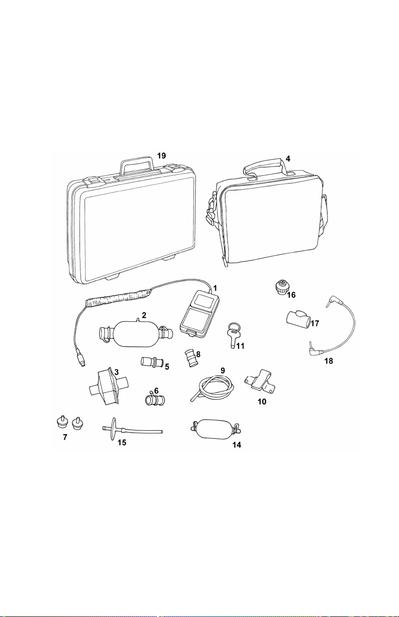
1.1 Parts List
Carefully unpack the test system components from the shipping
container. Check the individual parts against the packing list and
notify TSI immediately if anything is missing or damaged.
summarizes the Certifier
numbers shown in
®
FA Test System components and part
Figure 2.
Table 1
Figure 2. Certifier
1: Introduction
®
FA Test System Parts
3
Page 10

Table 1. Certifier
®
FA Test System Parts List
Item
no.
Description
Part
no.
Qty
High Flow standard kit (part no. 4070)
1 Controller module 4078 1
2 High Flow module 4071 1
3 Bacteria filter, 22-mm x 22-mm
1602341 1
male/female, for use with High Flow
module (single use)
4 Soft carrying case (holds Certifier® FA Test
1319289 1
System and accessories)
5 Adapter, 15-mm ID x 22-mm OD 1102093 1
6 Airway pressure fitting with screen 1611330 1
7 Adapter, 22-mm x 6-mm (for interfacing
1102091 2
High Flow module to Low Flow filter, for
use with oxygen concentrator)
8 Tube junction connector, 22-mm x 22-mm 1102094 1
9 Pressure tubing, 1/8-in. ID x 1/4-in. OD x
3002053 1
48-in. length, silicone
10 Mounting bracket (includes mounting
1040044 1
bracket, screws, and Velcro strap)
11 Pocket driver (used to remove/install the
3012034 1
controller module battery cover)
12 AA batteries (not shown) NA 4
13 Certifier® FA Test System Operator’s
1980436 1
Manual (not shown)
4
1: Introduction
Page 11

Table 1. Certifier
®
FA Test System Parts List (cont)
Item
no.
Description
Part
no.
Qty
Low Flow standard kit (part no. 4075)
1 Controller module 4078 1
14 Low Flow module 4074 1
15 Bacteria filter, barbed fittings, for use with
1040045 1
Low Flow module (single use)
4 Soft carrying case (holds Certifier® FA Test
1319289 1
System and accessories)
10 Mounting bracket (includes mounting
1040044 1
bracket, screws, and Velcro strap)
11 Pocket driver (used to remove/install the
3012034 1
controller module battery cover)
12 AA batteries (not shown) NA 4
13 Certifier® FA Test System Operator’s
1980436 1
Manual (not shown)
High Flow module kit (optional) (part no. 4076)
2 High Flow module 4071 1
3 Bacteria filter, 22-mm x 22-mm
1602341 1
male/female, for use with High Flow
module (single use)
5 Adapter, 15-mm ID x 22-mm OD 1102093 1
6 Airway pressure fitting with screen 1611330 1
7 Adapter, 22-mm x 6-mm (for interfacing
1102091 2
High Flow module to Low Flow filter, for
use with oxygen concentrator)
8 Tube junction connector, 22-mm x 22-mm 1102094 1
9 Pressure tubing, 1/8-in. ID x 1/4-in. OD x
3002053 1
48-in. length, silicone
10 Mounting bracket (includes mounting
1040044 1
bracket, screws, and Velcro strap)
1: Introduction
5
Page 12
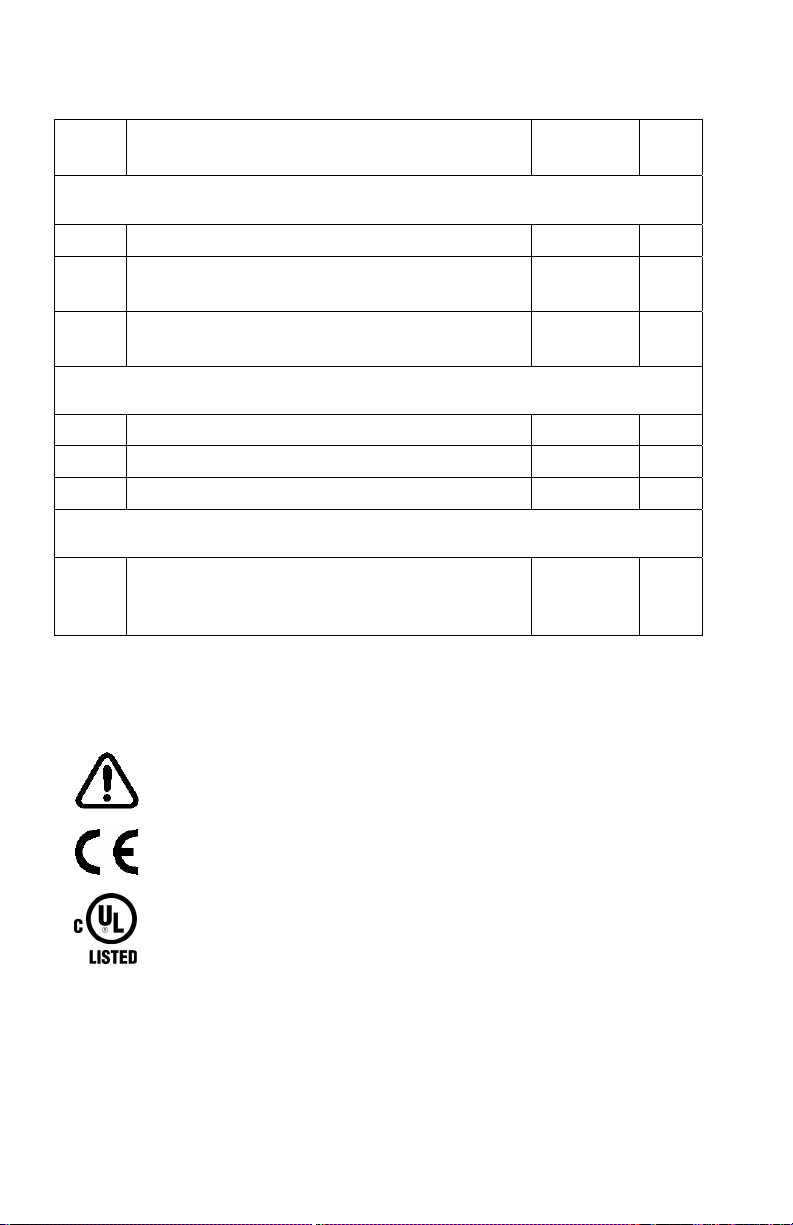
Table 1. Certifier
®
FA Test System Parts List (cont)
Item
no.
Description
Part
no.
Low Flow module kit (optional) (part no. 4072)
14 Low Flow module 4074 1
15 Bacteria filter, barbed fittings, for use with
1040045 1
Low Flow module (single use)
10 Mounting bracket (includes mounting
1040044 1
bracket, screws, and Velcro strap)
Oxygen sensor kit (optional) (part no. 4073)
16 Oxygen sensor 2917019 1
17 Threaded tee 1313118 1
18 Cable, 8-in. length 1303741 1
Other accessories (optional)
19 Hard shell carrying case (holds
Certifier
®
FA Test System and
1319288 1
accessories)
1.2 Glossary
These labels, terms, and symbols appear on the Certifier® FA Test
System:
Refer to manual: see Certifier
Manual for important information.
CE marking of European Conformity for the Low Voltage
Directive (LVD) and the Directive for Electromagnetic
Compatibility (EMCD).
®
FA Test System Operator’s
Qty
Safety approvals for Canada by Underwriter’s Laboratories
Inc. (UL).
See Section
appear on the Certifier
3.7 for definitions of symbols and abbreviations that
®
FA display.
6
1: Introduction
Page 13

2 Setup
Follow these steps to set up the Certifier® FA Test System:
CAUTION:
To avoid damage to the Certifier® FA Test System components,
always use bacteria filters upstream of the flow modules, and always
cap flow module ports when not in use.
1. Connect the controller module to a flow module (Figure 3).
To remove the cable, pull its locking connector (not the cable)
from the controller module.
Controller
module
Flow
module
Figure 3. Connecting the Controller Module to a Flow Module
7
Page 14

2. Attach the bacteria filter to the flow module (Figure 4).
Install the bacteria filter to the flow module inlet or upstream of all
Certifier
®
FA Test System components. Make sure the filter is in
the correct orientation by aligning the filter’s flow arrow with the
direction of the flow, ensuring that the filter’s inlet indicator
(labeled “INLET”, “I”, or other) faces upstream of the flow module,
or that the outlet indicator (label “Patent side”, “Outlet” or other)
faces towards the flow module.
Controller
module
High Flow filter
High Flow module
(note flow direction)
Low Flow
filter
Low Flow module
(note flow direction)
Figure 4. Connecting the Bacteria Filters to the Flow Modules
8 2: Setup
Page 15

3. High Flow module only: install pressure tubing (
Figure 5).
Attach one end of the pressure tubing to the low-pressure port on
the flow module, and the other to the pressure port in the circuit.
Pressure
tubing
High Flow module
Figure 5. Attaching Pressure Tubing to the High Flow Module
2: Setup 9
Page 16

4. High Flow module only: install the oxygen sensor (optional,
Figure 6).
Plug the oxygen sensor cable into the High Flow module and
oxygen sensor. Turn the cable collar to secure the cable to the
oxygen sensor. Use the threaded tee to install the oxygen sensor
into the circuit. The oxygen sensor can only connect to the High
Flow module.
Oxygen sensor
cable
Oxygen
sensor
Threaded tee
High Flow module
Figure 6. Attaching the Oxygen Sensor to the High Flow Module
10 2: Setup
Page 17

5. Install the flow module into the test circuit (
Figure 7, Figure 8).
Align the flow direction of the flow module and filter with the
direction of flow through the circuit.
Ventilator
Figure 7. Installing a Flow Module into the Test Circuit
2: Setup 11
Page 18

Oxygen
Concentrator
Figure 8. Certifier
®
FA Test System Installed in an Oxygen
Concentrator Circuit
12 2: Setup
Page 19

3 Operation
3.1 Power Up
Pull the protective caps from the flow module ports before powering
up. Do not apply pressure to the flow module at power up (this
ensures accurate low-pressure transducer zero calibration).
Press the I/O (on/off) key on the controller module to power up the
Certifier
attached Certifier
controller module shows information in this sequence:
1. All LCD segments light (about two seconds).
2. Firmware revision shown (about two seconds).
3. Controller module verifies connection and correct operation of the
4. Default measurements displayed:
®
FA Test System (the controller module powers all of the
®
FA Test System components). At power up, the
NOTE: If battery voltage is below the minimum operating level,
the battery symbol lights and the controller module will turn off.
flow module and oxygen sensor (if installed). If the oxygen
sensor is installed, the controller module will display a
symbol.
High Flow module: flow (top line), low pressure (bottom line).
Low Flow module: flow (top line), respiratory rate (bottom line).
CAUTION:
To ensure accurate measurements, wait about one minute for the
Certifier® FA Test System to warm up. If environmental conditions
have changed significantly, more time may be necessary.
To avoid damage to the Certifier® FA Test System components,
always use bacteria filters upstream of the flow modules, and
always cap flow module ports when not in use.
If liquid has penetrated any of its components, do not use, and
return to the factory for calibration.
The test system conserves battery life by automatically turning off if
none of the keys are pressed for 15 minutes. To override the
automatic turn off, press the GAS SELECT key with the I/O key when
turning on. The
will appear while the software revision is
displayed during power up if the automatic turn off is disabled.
13
Page 20

3.2 Keypad Functions
F
T
Table 2 summarizes the primary functions of the Certifier® FA Test
System keypad (
Figure 9).
Top line
select key
Bottom line
select key
ON/OF
key
DISPLAY
UNITS key
GAS SELEC
key
Backlight
on/off key
Figure 9. Controller Module Keypad
Table 2. Keypad Functions
Key Primary Function
Selects the measurement shown on the
Top line select
Bottom line select
top line of the display.
Selects the measurement shown on the
bottom line of the display.
Turns the system on (I) or off (O).
ON/Off
DISPLAY UNITS Selects the unit of measure for
measurements.
GAS SELECT Selects the supply gas type for the
Certifier
®
FA.
Turns the controller module display
Backlight on/off
backlight on or off.
3.3 Displaying Test Measurements
Follow these steps to display test measurements:
®
1. Set up the Certifier
2. Press the I/O (on/off) key to power up the system.
3. Once power up is complete, press the Top line select and
Bottom line select keys to select the measurements to be
14 3: Operation
FA Test System and install it into the circuit.
Page 21

displayed. See Section
3.4, Measurements, for details on each
parameter.
You can change the display selections and connect or disconnect the
flow module or oxygen sensor at any time during normal operation.
If you disconnect the flow module, the controller module display
is blank.
If you disconnect the oxygen sensor, the sensor symbol and any
oxygen-related measurements are not shown on the display.
Normal operation and display resume about one second after
reconnection.
®
NOTE: The Certifier
measurements that are recalculated at every breath. The Certifier
FA Test System automatically updates
®
FA Test System uses a threshold flow to determine the beginning and
end of each breath. The threshold flow calculated from the last three
breaths, is updated at each breath, and then is applied to the
following breath. Breath measurement displays begin after two full
breaths.
CAUTION:
To avoid damage to the Certifier® FA Test System components,
always use bacteria filters upstream of the flow modules, and always
cap flow module ports when not in use.
3.4 Measurements
Measurements on Top Line of Display
The following parameters are displayed on the top line of the display.
The Top Line Select key
momentarily pressing and then releasing the key.
3.4.1 Flow Rate
The flow rate can be displayed on the top line of control module
display. Units of standard liters per minute, indicated by “SLPM”, and
actual liters per minute, indicated by “LPM”, can be selected using the
DISPLAY UNITS key. For the High Flow module air, O
mixture (when oxygen sensor is attached) can be selected using the
GAS SELECT key. For the Low Flow module air, O
selected using the GAS SELECT key.
3:Operation 15
is used to scroll through parameters by
, and air/O2
2
, and N2O can be
2
Page 22

3.4.2 Peak Flow Rate
Maximum flow rate during the inhalation cycle of a breath can be
displayed on the top line of the control module display. Units of
standard liters per minute, indicated by “PEAK SLPM”, and actual
liters per minute, indicated by “LPM”, can be selected using the
DISPLAY UNITS key. See Section
3.7, Display Information, for
definitions of these units of measure. For the High Flow module air,
, and air/O2 mixtures can be selected using the GAS SELECT key.
O
2
For the Low Flow module air, O
, and N2O can be selected using the
2
GAS SELECT key.
NOTE: A valid flow cycle must occur for this value to be displayed.
See Section
3.6, Breathing Cycles and Trigger Levels, for details.
3.4.3 Volume
Volume that occurs during the inhalation cycle of a breath can be
displayed on the top line of the control module display. Units of
actual liters, indicated by “ATP L”; standard liters, indicated by “STP
L”; or liters at body temperature and pressure saturated, indicated by
“BTPS L” can be selected using the DISPLAY UNITS key. See
Section
measure. For the High Flow module air, O
3.7, Display Information, for definitions of these units of
, and air/O2 mixture can
2
be selected using the GAS SELECT key. For the Low Flow module
, and N2O can be selected using the GAS SELECT key.
air, O
2
NOTE: A valid flow cycle must occur for this value to be displayed.
See Section
3.6, Breathing Cycles and Trigger Levels, for details.
3.4.4 Minute Volume
Minute volume calculated from the inhalation cycle of the last breath
and breath rate can be displayed on the top line of the control module
display. Units of “MINUTE VOL ATP L” (actual liters), “MINUTE VOL
STP L” (standard condition liters), or “MINUTE VOL BTPS L” (liters at
body temperature and pressure saturated) can be selected using the
DISPLAY UNITS key. See Section
3.7, Display Information, for
definitions of these units of measure. For the High Flow module air,
, and air/O2 mixture can be selected using the GAS SELECT key.
O
2
For the Low Flow module air, O
, and N2O can be selected using the
2
GAS SELECT key.
NOTE: A valid flow cycle must occur for this value to be displayed.
See Section
3.6, Breathing Cycles and Trigger Levels, for details.
16 3: Operation
Page 23

3.4.5 Stacked Volume
Total volume over a displayed number of inhalation cycles can be
displayed on the top line of the control module display with the
number of inhalation cycles displayed on the bottom line of the
display. Units of actual liters, indicated by “ATP S L”; standard liters,
indicated by “STP S L”; or liters at body temperature and pressure
saturated, indicated by “BTPS S L” can be selected using the
DISPLAY UNITS key. See Section
3.7, Display Information, for
definitions of these units of measure. For the High Flow module air,
, and air/O2 mixture can be selected using the GAS SELECT key.
O
2
For the Low Flow module air, O
, and N2O can be selected using the
2
GAS SELECT key.
NOTE: A valid flow cycle must occur for this value to be displayed.
See Section
3.6, Breathing Cycles and Trigger Levels, for details.
3.4.6 Oxygen Concentration
When the oxygen sensor is attached to the High Flow module the
oxygen concentration “%O
” can be displayed on the top line of the
2
control module display. Oxygen concentration can also be displayed
on the bottom line of the display, see Section
3.4.14.
Daily calibrations need to be done on the oxygen sensor. See
Section
3.5.2 for instructions on oxygen sensor calibration.
NOTE: The
symbol will appear on the display when the oxygen
cable is attached.
Measurements on Bottom Line of Display
The following parameters are displayed on the bottom line of the
display. The Bottom line select key
is used to scroll through
parameters by momentarily pressing and then releasing the key.
3.4.7 Low Pressure
Gauge pressure from the low-pressure port of the High Flow module
can be displayed on the bottom line of the control module display.
Select units of “cmH
O” or “mmHg” by pressing and holding the
2
DISPLAY UNITS key for at least three seconds.
For best results check the zero on the low pressure transducer before
measurements. See Section
3.5.1 for instructions on zeroing the
pressure transducer.
NOTE: For distinguishing low pressure from absolute pressure, the
resolution for low pressure is in 0.1 cmH
O or mmHg and absolute
2
3:Operation 17
Page 24

pressure measurement (Section
3.4.13) is displayed in resolution of
1 mmHg.
3.4.8 Peak Pressure
Peak gauge pressure from the low-pressure port of the High Flow
module during the inhalation cycle can be displayed on the bottom
line of the control module display. Select units of “PEAK cmH
O” or
2
“PEAK mmHg” by pressing and holding the DISPLAY UNITS key for
at least three seconds.
NOTE: A valid flow cycle must occur for this value to be displayed.
See Section
3.6, Breathing Cycles and Trigger Levels, for details.
For best results check the zero on the low pressure transducer before
measurements. See Section
3.5.1 for instructions on zeroing the
pressure transducer.
3.4.9 Peep Pressure
Positive end expiratory pressure (PEEP) from the low-pressure port
of the High Flow module can be displayed on the bottom line of the
control module display. Select units of “PEEP cmH
O” or “PEEP
2
mmHg” by pressing and holding the DISPLAY UNITS key for three
seconds.
For best results check the zero on the low pressure transducer before
measurements. See Section
3.5.1 for instructions on zeroing the
pressure transducer.
NOTE: A valid flow cycle must occur for this value to be displayed.
See Section
3.6, Breathing Cycles and Trigger Levels, for details.
3.4.10 Breath Rate
The breaths per minute (BPM) can be displayed on the bottom line of
the control module display.
NOTE: A valid flow cycle must occur for this value to be displayed.
See Section
3.6, Breathing Cycles and Trigger Levels, for details.
3.4.11 I:E Ratio
The ratio of the inhalation time and exhalation time (I:E RATIO) can
be displayed on the bottom line of the control module display.
NOTE: A valid flow cycle must occur for this value to be displayed.
See Section
3.6, Breathing Cycles and Trigger Levels, for details.
NOTE: The inhalation time is defined as the time of positive
inhalation flow and does not include the breath hold time. If the vents
18 3: Operation
Page 25

inhalation time includes the inhalation pause time, the Certifier
®
FA’s
I:E ratio will not match the vents I:E ratio.
3.4.12 I Time
The inhalation time (I TIME) can be displayed on the bottom line of
the control module display.
NOTE: A valid flow cycle must occur for this value to be displayed.
See Section
3.6, Breathing Cycles and Trigger Levels, for details.
NOTE: The inhalation time is defined as the time of positive
inhalation flow and does not include the breath hold time. If the vents
pause inhalation time includes a pause time, the Certifier
®
FA’s I time
will not match the vents I time.
3.4.13 Absolute Pressure
The absolute pressure in the flow tubes can be displayed on the
bottom line of the control module display in units of “mmHg”.
NOTE: For distinguishing absolute pressure from low pressure, the
resolution for absolute pressure measurement is displayed in a
resolution of 1 mmHg and low pressure (Section
in a resolution of 0.1 cmH
O or mmHg.
2
3.4.7) is displayed
3.4.14 Oxygen Concentration
When the oxygen sensor is attached to the High Flow module, the
oxygen concentration “%O
” can be displayed on the bottom line of
2
the control module display. Oxygen concentration can also be
displayed on the top line of the display. See Section
3.4.6.
Daily calibrations need to be done on the oxygen sensor. See
Section
3.5.2 for instructions on oxygen sensor calibration.
NOTE: The
symbol will appear on the display when the oxygen
cable is attached.
3.5 Required Pre-test Calibrations
3.5.1 Low-Pressure Transducer Zero Calibration
®
The Certifier
transducer zero calibration at power up. Check the low pressure zero
by disconnecting the pressure tubing from the flow module before
each low-pressure measurement after initial power up to ensure the
most accurate readings. If low pressure is not reading zero, perform
the following steps to zero the transducer.
3:Operation 19
FA Test System automatically performs a low-pressure
Page 26

1. Disconnect the pressure tubing from the flow module to expose
the flow module to ambient air.
2. Momentarily press the Bottom line select key until low pressure
(see Section
3.4.7) is shown on the display.
3. Press and hold the Bottom line select key for 2 to 3 seconds.
The display shows ZERO to indicate that the zero calibration is in
progress.
4. When ZERO is no longer displayed, the low-pressure transducer
zero calibration is complete.
NOTE: The barometric pressure transducer does not require a zero
calibration.
3.5.2 Oxygen Sensor Calibration
Follow these steps daily and following an altitude change or sensor
replacement to calibrate the oxygen sensor:
®
1. Power up the Certifier
FA Test System with the High Flow
module and oxygen sensor attached, then allow about one
minute to warm up. The oxygen sensor symbol flashes if the
controller module detects the sensor needs calibration or has
expired.
2. Momentarily press the Top line select or Bottom line select key
to show %O
on the display.
2
3. Press and hold the GAS SELECT key for 2 to 3 seconds. Expose
the oxygen sensor to room air when you see 21.0 %O
on the display. The 21% calibration is complete when 100.0 %O
and CAL
2
2
lights up on the top line and CAL flashes on the display. This can
take several minutes while the oxygen concentration and sensor
stabilize.
4. Expose the oxygen sensor to 100% oxygen of at least 5 liters per
minute. Press and release the GAS SELECT key to begin the
100% calibration. CAL stops flashing when the 100% calibration
begins.
5. If the calibration is successful, CAL disappears and the O
2
concentration is shown on the display. This can take several
minutes while the oxygen concentration and sensor stabilize.
6. If the calibration is not successful (oxygen sensor symbol
continues to flash, no O
concentration is shown), repeat the
2
calibration. If the repeated calibration is not successful, replace
the oxygen sensor and repeat.
®
7. Expose the oxygen sensor to room air. The Certifier
System is ready to use when the %O
reading returns to
2
FA Test
approximately 21%.
20 3: Operation
Page 27

3.6 Breathing Cycles and Trigger Levels
The Certifier® FA uses flow rate to trigger the beginning and the end
of a ventilator’s inhalation cycle.
3.6.1 Inhalation and Exhalation Timing
At the beginning of the inhalation cycle the flow rate must be above
the trigger flow rate for at least 0.25 milliseconds. If this time is less
than 0.25 milliseconds, the Certifier
exhalation cycle. When a valid inhalation cycle is ending and the flow
rate goes below the trigger level, the flow rate must remain below the
trigger level for at least 0.25 milliseconds, otherwise, this period is
included in the inhalation cycle.
If testing of ventilator pressure modes is needed, a test lung must be
used to ensure that a long enough flow delivery time is generated. If
there is not enough volume in the breathing circuit, the pressure can
be generated in less than 0.25 milliseconds.
3.6.2 Flow Trigger Levels
The default trigger level is automatically set on power up at the 20%
point from the minimum flow to the peak flow. For example, if the
maximum flow rate is 80 L/min and the minimum flow is 5 L/min, then
the trigger flow rate is set to (80 L/min – 5 L/min) x 20% + 5 L/min =
20 L/min. The 20% auto trigger level will work for most ventilators,
but some manufactures may instruct you to select a different trigger
level.
A 10% of the peak flow rate and trigger can also be selected. The
10% auto trigger does not use the minimum flow rate in calculating
the trigger level; zero is assumed for the minimum flow rate. In the
above example the trigger level would be 80 L/min x 10% = 8 L/min.
Manually set trigger levels can also be used. Trigger can be
manually set at 1, 2, 3, 4, 5, 6, 7, 8, 9, 10, 12, 15, 17, 20, 22, 24, 30,
35, or 40 L/min.
Follow these steps to view or adjust the flow trigger level.
1. Momentarily press the Top line select key until volume
parameter is on the display, see Section
2. Press and hold the Top line select key until the “trig” appears on
the bottom of the display.
3. The trigger value will appear on the top line of the display which
will be one of the following: “20 PEAK” (20% Auto trigger),
“1 LPM”, “2 LPM”, “3 LPM”, “4 LPM”, “5 LPM”, “6 LPM”, “7 LPM”,
“8 LPM”, “9 LPM”, “10 LPM”, “12 LPM”, “15 LPM”, “17 LPM”,
®
FA considers this part of the
3.4.3.
3:Operation 21
Page 28

“20 LPM”, “22 LPM”, “25 LPM”, “30 LPM”, “40 LPM”, or
“10 PEAK” (10% Auto trigger).
4. To adjust the value, press and release the Top line select or
Bottom line select to scroll through the list of values in step 3.
After 3 seconds the new trigger level will be set and the interface
module will return to displaying volume.
NOTE: The default value of 20% auto trigger is restored once the
controller module is turned off.
3.7 Display Information
Table 3 describes information that can appear on the controller
module screen.
Table 3. Screen Displays
Display Meaning
- - - An out-of-range measurement.
Oxygen sensor symbol: indicates presence of
oxygen sensor. Flashes to indicate that sensor must
be calibrated or replaced.
Low battery voltage symbol: indicates that batteries
should be replaced.
%O2 Oxygen concentration can be displayed on either
line if High Flow module and oxygen sensor are
attached.
AIR
AIR O2 Mixed air and oxygen supply gas, selected using the
ATP Atmospheric temperature and pressure: a condition
BPM Breaths per minute: a unit of respiratory rate. Can
Air supply gas, selected using the GAS SELECT
key (when High Flow or Low Flow module is
attached).
GAS SELECT key (when High Flow module and
oxygen sensors are attached).
®
of volume measurement. The Certifier
FA Test
System calculates the ATP value by applying the
actual gas temperature and pressure to the STP
measurement.
be displayed on the bottom line (either High Flow or
Low Flow module attached).
22 3: Operation
Page 29

Table 3. Screen Displays (cont.)
Display Meaning
BTPS Body temperature and pressure, saturated: a
condition of volume measurement. The Certifier
®
FA
Test System calculates a BTPS value by
compensating the STP measurement for BTPS
conditions (37 °C (98.6 °F), ambient pressure,
100% relative humidity).
CAL 100%
O
2
Oxygen sensor calibration in progress (during
exposure to 100% O2).
CAL 21% O2 Oxygen sensor calibration in progress (during
exposure to room air).
cmH2O Centimeters of water: a unit of pressure.
I TIME Inspiratory time (in seconds). Can be displayed on
the bottom line (either High Flow or Low Flow
module attached).
I:E RATIO Ratio of inspiratory time to expiratory time, can be
displayed on the bottom line (when High Flow or
Low Flow module is attached).
L Liter: a unit of volume.
LPM Liters per minute: a unit of flow. The Certifier® FA
Test System calculates the LPM value by applying
the actual gas temperature and pressure to the
SLPM measurement.
MINUTE VOL Minute volume: an estimate of exhaled volume for
the next 60 seconds, based on the current breath.
Can be displayed on the bottom line (when High
Flow or Low Flow module is attached).
mmHg Millimeters of mercury: a unit of pressure.
N2O 100% nitrous oxide supply gas, selected using the
GAS SELECT key (if Low Flow module is attached).
O2
100% oxygen supply gas, selected using the GAS
SELECT key (when High Flow or Low Flow module
is attached).
3:Operation 23
Page 30

Table 3. Screen Displays (cont.)
Display Meaning
PEAK Peak flow or pressure. Peak flow can be displayed
on top line (when High Flow or Low Flow module is
attached). Peak pressure can be displayed on
bottom line (if High Flow module is attached).
PEEP Positive end expiratory pressure: the minimum
pressure measured in the circuit throughout the
breath cycle. Can be displayed on the bottom line (if
High Flow module attached).
REV Software revision level, displayed at power up.
S Stacked volume: a cumulative volume measurement
for consecutive breaths. The top line shows the
cumulative volume and the bottom line shows the
number of consecutive breaths.
SEC Seconds, a unit of time for I TIME measurements.
SLPM Standard liters per minute: a unit of flow. The
Certifier
®
FA Test System measures flows in SLPM.
Standard conditions are defined as 21.1 °C (70 °F)
at 101.3 kPa (14.7 psia).
STP Standard temperature and pressure: a condition of
volume measurement. The Certifier
®
FA Test
System measures volumes at STP. Standard
conditions are defined as 21.1 °C (70 °F) at
101.3 kPa (14.7 psia).
VOL Volume: the exhaled volume for the most recent
breath. Can be displayed on the top line (either High
Flow or Low Flow module attached).
ZERO Low-pressure transducer zero calibration in
progress.
24 3: Operation
Page 31

4 Troubleshooting
Table 4 lists the symptoms, possible causes, and recommended
corrective actions for problems you may encounter with the
Certifier
the recommended corrective actions solves the problem, please
contact TSI Customer Support at (800) 874-2811 or 651-490-2811.
Symptom Possible Cause Corrective Action
Controller module
won’t turn on, or
turns on and off.
Measurements
aren’t displayed
even though
controller module
is on.
‘---‘ is shown on
display.
Flow rate does
not read zero
when no gas
flowing
(Especially when
set to N
Unable to
disconnect flow
module from
controller module.
Can’t display
%O
®
FA Test System. If the symptom is not listed, or if none of
®
Table 4. Troubleshooting the Certifier
Batteries are
depleted or installed
backwards.
Flow module isn’t
connected to
FA Test System
Check that batteries
are installed correctly.
Replace batteries.
Connect flow module to
controller module.
controller module.
Measurement is out
of range.
Check range for
displayed
measurement, and only
make measurements
within that range.
Meter was not
purged with gas
displayed on the
controller.
Purge meter with gas
displayed on controller
or press gas select key
to change to desired
gas.
O).
2
Pulling on the cable
rather than the
connector.
Pull the locking
connector (not the
cable) to disengage
connector lock.
Oxygen sensor not
.
2
connected. Look for
oxygen sensor
Connect oxygen sensor
cable to High Flow
module and oxygen
sensor.
symbol,
.
25
Page 32

Table 4. Troubleshooting the Certifier
®
FA Test System (cont.)
Symptom Possible Cause Corrective Action
Can’t select
AIR O
mixtures.
2
Oxygen sensor not
connected. Look for
oxygen sensor
Connect oxygen sensor
cable to High Flow
module and oxygen
sensor.
.
Wait for at least two
consecutive full breaths
to be supplied to the
flow module.
Ensure that flow is
supplied as a breathing
waveform.
Manually set flow
trigger level.
®
Certifier
FA can not
measure shorter than
0.25 millisecond flow
delivery.
Use a test lung so that
at least 0.25
milliseconds of flow
delivery is generated to
Volume, minute
volume, peak
flow, peak
pressure, PEEP,
respiratory rate,
or I:E ratio
measurement
isn’t updated.
symbol,
Less than two
consecutive full
breaths have been
supplied to flow
module, or flow is
not supplied as a
breathing waveform.
Bias flow is greater
than auto trigger
level.
Inhalation cycle is
less than 0.25
milliseconds
Testing pressure
mode on ventilator
and no test lung
attached.
generate pressure.
Can’t change
measurement
units.
Measurement isn’t
displayed while
changing units.
Press the Top line
select or the Bottom
line select key to
display measurement,
then press the
DISPLAY UNITS key to
change units.
Can’t zero lowpressure
transducer.
Transducer is
connected to a
pressure source.
Disconnect pressure
tubing from flow
module, then zero lowpressure transducer.
Can’t zero
barometric
pressure
transducer.
Barometric pressure
transducer does not
require a zero
calibration.
Resume normal system
operation.
26 4: Troubleshooting
Page 33

Table 4. Troubleshooting the Certifier
®
FA Test System (cont.)
Symptom Possible Cause Corrective Action
Oxygen sensor
calibration takes
longer than 5
minutes.
21% oxygen and/or
100% oxygen not
supplied for
calibration.
Flow of 100%
oxygen is too low.
Verify that calibration
gases are 21% oxygen
and 100% oxygen and
repeat calibration.
Increase flow of 100%
oxygen to at least 5
SLPM and repeat
calibration.
Oxygen sensor
calibration fails.
21% oxygen and/or
100% oxygen not
supplied for
calibration.
Oxygen sensor is
expired.
Verify that calibration
gases are 21% oxygen
and 100% oxygen and
repeat calibration.
Replace oxygen
sensor.
4:Troubleshooting 27
Page 34

Page 35

5 Maintenance
5.1 Replacing the Batteries (as required)
Replace the batteries when the low battery voltage symbol is
displayed or instrument will not power up.
1. Turn off the controller module.
2. Use the pocket driver tool (supplied) to loosen the screw that
holds the battery cover on the controller module back panel.
3. Remove the old batteries from the battery compartment, and
install new batteries noting the polarity indicators.
4. Reinstall the battery cover and tighten the screw to hold the cover
to the controller module.
5.2 Replacing the Oxygen Sensor (yearly)
The oxygen sensor will function for one year of normal operation if
use begins before the expiration date. Replace the oxygen sensor
every year of normal use, or if the sensor cannot be calibrated or
sensor readings are erratic.
5.3 Cleaning (as required)
Table 5 summarizes recommended cleaning methods for
Certifier
Component Cleaning
Controller module
Flow modules
Carrying cases
Oxygen sensor
Oxygen sensor cables
Tee
Adapters
Single use filters (high
®
FA Test System components.
Table 5. Cleaning Recommendations
and Low Flow
modules)
Clean exterior as required with a clean
cloth and isopropyl alcohol, hydrogen
peroxide (3%), or ammonia (15%).
Steam autoclave after contact with any
non-sterile breathing circuit
components, and discard if any damage
is visible.
Discard after contact with any nonsterile breathing circuit components or if
damage is visible.
29
Page 36

5.4 Factory Calibration (yearly)
Certifier® FA Test System flow modules are designed for one year of
normal use following each factory calibration.
If the test system has been dropped or liquid has penetrated any of its
components, do not use, and return to the factory for calibration.
Recalibrated flow modules come with a certificate of calibration and a
summary of performance before and after the calibration. A factory
calibration consists of pressure transducer calibration over the full
range of pressures and calibration over the full range of flows. All
calibration datum are stored in the flow modules, so the controller
module does not require calibration. Therefore, it is not necessary to
return the controller module for factory calibration.
Follow the steps in Section
flow modules for factory calibration.
5.5 to return Certifier® FA Test System
5.5 Return Procedure
Follow these steps to return Certifier® FA Test System flow modules
for factory calibration:
1. Contact one of the following offices to make service
arrangements and obtain a Return Material Authorization (RMA)
number or use our online RMA form at
2. Package the flow modules carefully to avoid damage during
shipping.
NOTE: It is not necessary to return the controller module for
factory calibration.
www.tsi.com.
U.S. & International UK
TSI Incorporated TSI Instruments Ltd.
500 Cardigan Road Tel: (44) 1494 459200
Shoreview MN 55126-3996 Fax: (44) 1494 459700
USA E-mail:
Tel: (800) 874-2811 / Website:
+1(651) 490-2811
Fax : +1(651) 490-3824
E-mail:
Website:
30 5: Maintenance
technical.service@tsi.com
www.tsi.com
tsiuk@tsi.com
www.tsiinc.co.uk
Page 37

6 Specifications
NOTE: Specifications are subject to change without notice.
6.1 Physical
Dimensions Controller module: 13.2 cm x 7 cm x 3.3 cm (5.2 in. x 2.8 in. x 1.3 in.).
High Flow module: 18 cm x 6.6 cm x 4 cm (7.1 in. x 2.6 in. x 1.6 in.).
Low Flow module: 12.7 cm x 5.1 cm x 2.8 cm (5.0 in. x 2.0 in. x 1.1 in.).
Flow
connectors
Weight Approximately 1.36 kg (3 lb) for the standard kits.
6.2 Environmental
Temperature
Atmospheric
Pressure
Conditions Indoor Use
High Flow module:
• flow inlet: 22-mm female ISO taper.
• flow outlet: 22-mm male ISO taper.
Low Flow module:
• flow inlet: 0.25-in. barb.
• flow outlet: 0.25-in. barb.
Operating: 5 to 40 °C (41 to 104 °F). 15 to 80% relative humidity from
5 to 31 °C decreasing linearly to 15 to 50% relative humidity at 40 °C.
Storage: -40 to 70 °C (-40 to 158 °F) at 10 to 95% relative humidity.
Operating: 57.1 to 106 kPa (8.28 to 15.37 psia).
Storage: 50 to 106 kPa (7.25 to 15.37 psia).
Operating Altitude up to 2000 m (6562 ft)
Pollution degree I or II
6.3 Power
Battery life 15 to 20 hours.
Battery type Four commercially available AA batteries.
6.4 Test Measurements (see notes at end of section)
Measurement High Flow Module Low Flow Module
Flow and Peak Flow
Range 0 to 300.0 SLPM. 0.01 to 15.00 SLPM.
Accuracy
Air and oxygen: ± 2% of reading
or ± 0.075 SLPM, whichever is
greater.
Air/oxygen mixtures: ± 4% of
reading or ± 0.1 SLPM, whichever
is greater.
Air and oxygen: ± 2% of
reading or ± 0.010 SLPM,
whichever is greater.
Nitrous oxide: ± 4% of reading
or ± 0.025 SLPM, whichever is
greater.
31
Page 38

Measurement High Flow Module Low Flow Module
Pressure drop Maximum between inlet and
outlet ports at 101.3 kPa (14.7
psia) including filter: 0.50 cmH
at 20 SLPM, 1.50 cmH
SLPM, 5.0 cmH
30.0 cmH
O at 300 SLPM.
2
O at 50
2
O at 100 SLPM,
2
Maximum between inlet and
outlet ports at 101.3 kPa (14.7
psia) including filter: 4 cmH
O
2
at 2 SLPM, 16 cmH
SLPM, 45 cmH
85 cmH
O at 15 SLPM.
2
2
O at 10 SLPM,
2
Volume
Range 0.01 to 10.0 L STP. 0 to 9.999 L STP.
Accuracy
Air and oxygen: ± 2% of reading
plus 0.020 L STP
Air/oxygen mixtures: ± 4% of
reading plus 0.020 L STP.
Air and oxygen: ± 2% of
reading or ± 0.010 L STP,
whichever is greater.
Nitrous oxide: ± 4% of reading
or ± 0.010 L STP, whichever is
greater.
Minute Volume
Range 0 to 99.00 L STP. 0 to 9.999 L STP.
Accuracy
± 7% of reading. ± 7% of reading.
Stacked Volume
Range 0 to 99.00 L STP. 0 to 9.999 L STP.
Accuracy
Air and oxygen: ± 2% of reading
plus 0.020 L STP
Air/oxygen mixtures: ± 4% of
reading plus 0.020 L STP.
Air and oxygen: ± 2% of
reading or ± 0.010 L STP,
whichever is greater.
Nitrous oxide: ± 4% of reading
or ± 0.010 L STP, whichever is
greater.
Inspiratory Time
Range 0.25 to 60.00 seconds. 0.25 to 60.00 seconds.
Accuracy
± 0.01 seconds. ± 0.01 seconds.
I:E Ratio
Range 1:100.0 to 100.0:1. 1:15.0 to 15.0:1.
Accuracy
± 5% of reading. ± 5% of reading.
Respiratory Rate
Range 0.5 to 120.0 breaths per minute. 0.5 to 120.0 breaths per
minute.
Accuracy
± 5% of reading. ± 5% of reading.
Low Pressure
Range -25.0 to 150.0 cmH2O.
Not applicable.
(-18.4 to 110 mmHg)
Accuracy
± 0.75% of reading or
± 0.20 cmH
O (0.15 mmHg),
2
Not applicable.
whichever is greater.
O at 5
O
2
32 6: Specifications
Page 39

Measurement High Flow Module Low Flow Module
Peak & PEEP Low Pressure
Range 0 to 150.0 cmH2O.
(0 to 110 mmHg)
Accuracy
Barometric Pressure
Range 375 to 1500 mmHg. 375 to 1500 mmHg.
Accuracy
Oxygen Concentration
Range 0 to 100.0% O2. Not applicable.
Accuracy
NOTES
1. Standard conditions are defined as 21.1 °C (70 °F) and 101.3 kPa (14.7 psia).
2. Flow and volume accuracy is applicable in SLPM or STP mode only.
3. The temperature of the gas and the ambient air must be within ± 10 °C (± 18 °F) of
each other and the gas must be less than 30% relative humidity at 21. 1 °C (70 °F).
4. Flow and volume accuracy de-rating: ± 0.075% of reading per 1 °C (1.8 °F) away
from 21.1 °C (70 °F); ± 0.015% of reading per 1.03 kPa (0.15 psia) above 101.3 kPa
(14.7 psia); ± 0.022% of reading per 1.03 kPa (0.15 psia) below 101.3 kPa (14.7
psia); ± 0.07% of reading per 1% relative humidity above 30% relative humidity.
± 0.75% of reading or ± 0.20
cmH
O (0.15 mmHg), whichever
2
is greater.
± 8 mmHg. ± 8 mmHg.
at daily calibration
± 2% O
2
conditions.
Not applicable.
Not applicable.
Not applicable.
6.5 Calibration Requirements
Flow modules Factory calibration every year for normal use under normal
Controller module No calibration required.
Oxygen sensor Daily, following sensor replacement or as required.
conditions using the filter(s) provided.
6.6 Compliance and Approvals
Complies with these
standards:
6: Specifications 33
• CAN/CSA-C22.2 No. 1010. 1-92: Canadian Standard for the
Safety of Electrical Equipment for Measurement, Control
and Laboratory Use, Part 1.
• EN 55011 (1991) Class B, CISPR 11 (1990) Class B, FCC
(CFR 47, Part 15) Class B: Emissions, Radiated and
Conducted.
• EMC Directive 89/336/ECC, EN 61326-1 (1997 plus
Amendment A1 1998), IEC 1000-4-2 (1995), EN 61000-4-2,
IEC 1000-4-3 (1995), EN 61000-4-3: Immunity.
Page 40

TSI Incorporated – 500 Cardigan Road, Shoreview, MN 55126 U.S.A
USA Tel: +1 800 874 2811 E-mail: info@tsi.com
UK Tel: +44 149 4 459200 E-mail: tsiuk@tsi.com
France Tel: +33 491 95 21 90 E-mail: tsifrance@tsi.com
Germany Tel: +49 241 523030 E-mail: tsigmbh@tsi.com
India Tel: +91 80 41132470 E-mail: tsi-india@tsi.com
China Tel: +86 10 8260 1595 E-mail: tsibeijing@tsi.com
Website: www.tsi.com
Website: www.tsiinc.co.uk
Website: www.tsiinc.fr
Website: www.tsiinc.de
Contact your local TSI Distributor or visit our website www.tsi.com for more detailed specifications.
P/N 1980436 Rev F Copyright © 2008 by TSI Incorporated Printed in U.S.A.
 Loading...