

Page 1
INSTALLATION GUIDE
EXHAUST ACCESSORY
3098-EX
The purpose of this accessory kit is to enable venting of the effluent of the Model 3098 Porous Tube
Thermodiluter (PTT) and the Model 3090 Engine Exhaust Particle Sizer™ (EEPS™) Spectrometer
(collectively known as the Model 3095 Engine Exhaust Particle Measurement System or EEPMS) through an
exhaust line into the user’s fume collection system. The following contains a description of the parts required
and the procedures needed to install this accessory kit. For replacement fitting kits or tubing, contact TSI®.
Table 1. Bill of Materials for 3098-EX
Quantity
Required
Description
Swagelok®
Part Number
Picture
1
Stainless Steel Female Branch Tee,
3/8 in. Tube OD x 3/8 in.
Tube OD x 3/8 in. Female NPT
SS-600-3-6TTF
1
Stainless Steel Male Connector,
3/8 in. Tube OD x 3/8 in. Male NPT
SS-600-1-6
1
Stainless Steel Male Connector,
1/2 in. Tube OD x 3/8 in. Male NPT
SS-810-1-6
1
Stainless Steel Tube Fitting, Union,
3/8 in. Tube OD
SS-600-6
1
Stainless Steel Tube Fitting, Port
Connector, 3/8 in. Tube OD
SS-601-PC
2
Stainless Steel Tubing insert,
3/8 in. OD x 0.277 in. ID
SS-605-277
1
Stainless Steel Tubing Insert,
1/2 in. OD x 3/8 in. ID
SS-815-6
2
Nylon Ferrule Set (1 Front Ferrule/
1 Back Ferrule) for 3/8 in. Tube Fitting
NY-600-SET
®
Swagelok is a registered trademark of Swagelok Company.
Page 2
Installation Guide Page 2 of 8 Exhaust Accessory 3098-EX
Quantity
Required
Description
Swagelok®
Part Number
Picture
1
316 Stainless Steel Nut for
3/8 in. Tube Fitting
SS-602-1
1
PTFE Tape Thread Sealant,
1/2 x 288 in. (12.7 x 732 cm)
MS-STR-8
25 ft
Ether-based polyurethane tubing,
1/2 in. OD, 3/8 in. ID, clear
N/A
5 ft
Ether-based polyurethane tubing,
3/8 in. OD, 1/4 in. ID, clear
N/A
Installation Instructions
1. Power down the Model 3090 EEPS™ Spectrometer and
Model 3098 PTT following the instructions in the Model 3090 and
Model 3098 manuals, respectively. Turn off the main disconnect
on the back of the Model 3098.
2. Remove the power and serial connections from the back of the
EEPS™ Spectrometer.
3. Completely loosen the Swagelok® nut connecting the output of the
PTT to the EEPS™ Spectrometer using an 11/16 in. open-ended
wrench.
4. Loosen the clamp securing the EEPS™ Spectrometer on to the
PTT. Remove the EEPS™ Spectrometer and set aside. The
instrument should now appear as shown in Figure 1.
5. Unscrew the handle from the rubber base of the hold-down clamp
using a 9/16 in. open-ended wrench. Remove the threaded handle
by unscrewing completely from the post.
6. Using a T30 Torx® driver, loosen the two quarter-turn screws
holding the front panel on the PTT. DO NOT use a tool other than
the correctly-sized Torx® driver, as the plastic screws may strip.
Remove the front panel by gently lifting up on the bottom (there
are two holes in the bottom of the panel that locate on two fixed
pins attached to the 3098 chassis) and sliding the panel off of the
hold-down clamp post. Set the panel aside.
Figure 1. The 3098 with the EEPS™
Spectrometer removed.
®
Torx is a registered trademark of Acument Intellectual Properties.
Page 3
Installation Guide Page 3 of 8 Exhaust Accessory 3098-EX
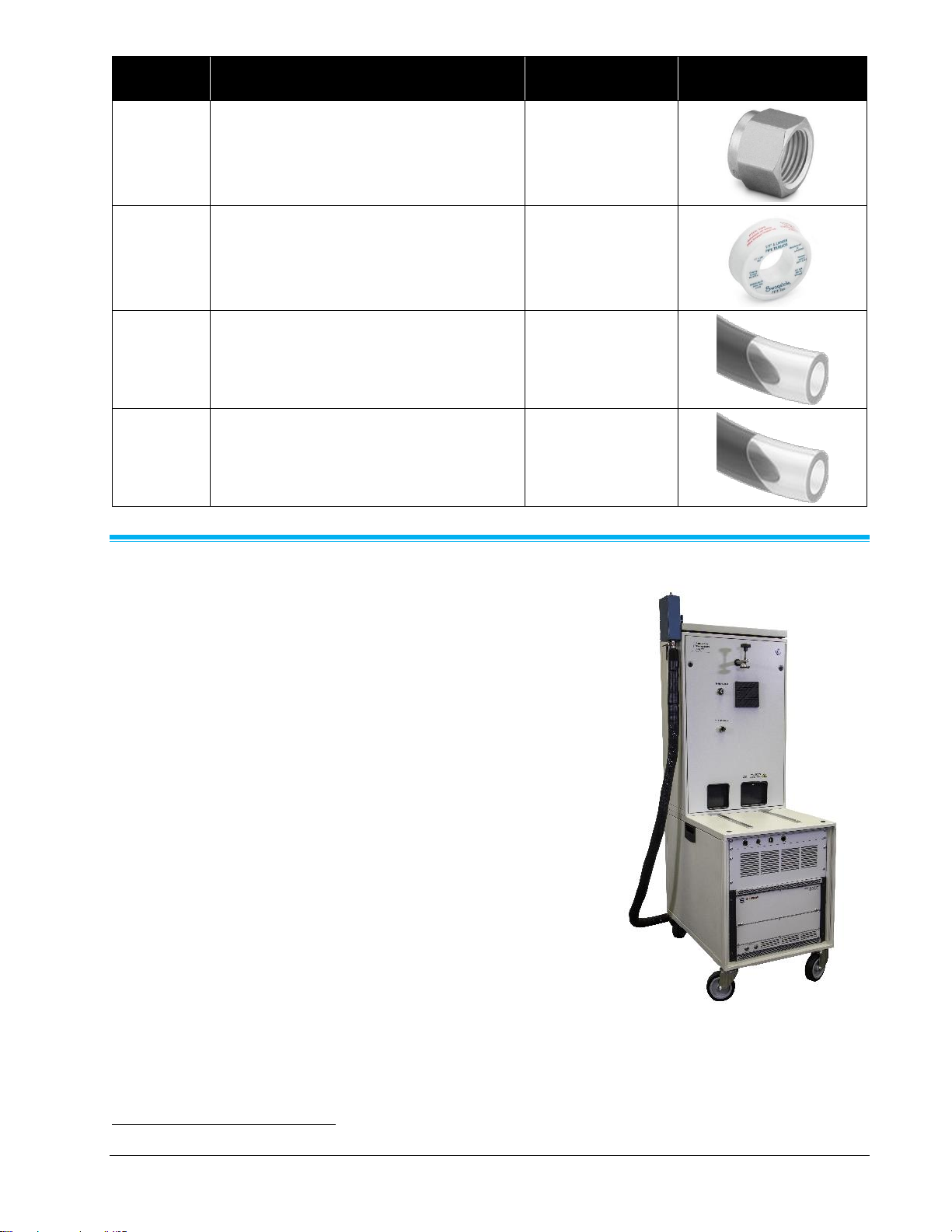
7. The vacuum pump is now visible. Remove the muffler from the exhaust port of the pump (see Figure 2),
and install the SS-600-1-6 fitting in its place as shown in Figure 3. Keep the muffler in a safe place in
case it needs to be reinstalled in the future. Be sure to apply PTFE tape to the threads of the fitting before
installation into the pump.
Figure 2. The factory-installed vacuum pump
muffler removed.
Figure 3. The vacuum pump with the replacement
fitting installed.
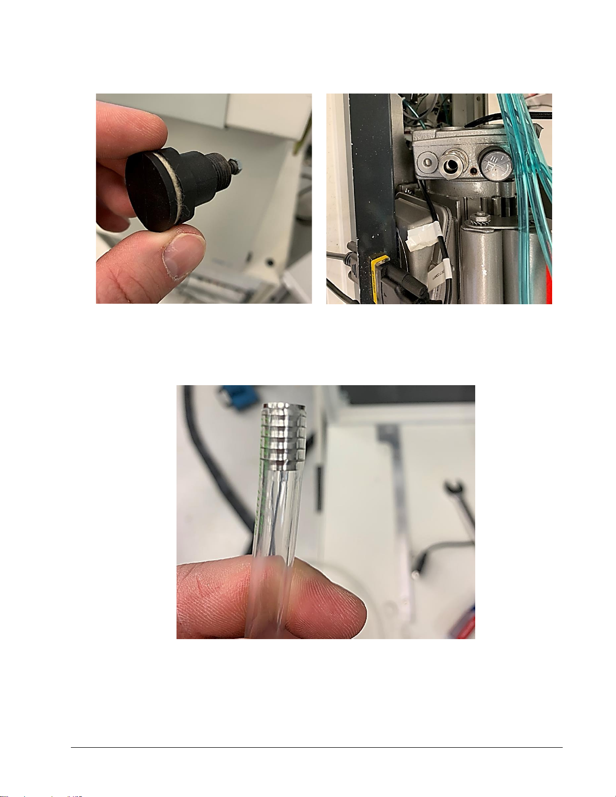
8. Cut a piece of the supplied 3/8 in. OD polyurethane tubing to approximately 15 in. (40 cm) in length.
Install one tubing insert into each end of the tube by pressing them in with your finger as shown in
Figure 4.
Figure 4. A piece of the 3/8 in. OD polyurethane tubing with the tubing inserts installed.
Page 4

Installation Guide Page 4 of 8 Exhaust Accessory 3098-EX
9. Push one end of the tubing through the nut in the newly-installed vacuum pump fitting until it completely
seats. You will experience appreciable resistance; this is normal. Make sure the metal ferrules are on the
portion of the tube that contains the metal insert. Tighten the nut firmly using an 11/16 in. open-end
wrench. The pump should now appear as shown in Figure 5.
Figure 5. The vacuum pump with the new tubing installed.
10. Remove the bottom metal grommet from the front cover panel of the PTT and reinstall so that the
protrusion is now on the inside. Both metal grommets should now protrude into the interior of the
instrument as shown in Figure 6.
Figure 6. The metal grommets in the PTT front cover panel.
Page 5

Installation Guide Page 5 of 8 Exhaust Accessory 3098-EX
11. Feed the vacuum pump tube through the bottom metal grommet of the PTT front cover panel. Feed the
EEPS™ Spectrometer power and serial cables through their cutout in the bottom of the panel. Reinstall
the panel on the PTT by aligning the hold-down clamp post with its corresponding hole in the cover, and
gently rotating the cover in such that the posts on the chassis align with the holes in the bottom of the
cover. Tighten the two quarter-turn screws with a T30 Torx® driver. DO NOT overtighten.
12. Assemble the EEPS™ Spectrometer inlet spacer fittings (SS-600-6 + SS-601-PC + SS-602-1). Remove
the front and back stainless steel ferrules from one side of the SS-600-6 union and replace with one set of
the nylon units. The side with the nylon ferrules will be attached to the EEPSTM inlet port connector. Install
the inlet spacer fittings on to the PTT diluted sample outlet fitting. See Figure 7 for a schematic of the
fitting stackup.
Figure 7. Swagelok® fitting stack up for EEPS™ Spectrometer inlet spacer (not to scale).
13. Assemble the exhaust tee fittings (SS-600-3-6TTF + SS-810-1-6). Be sure to apply PTFE tape to the
threads of the NPT fitting before installing it into the tee. Remove the front and back stainless steel
ferrules from one side of the tee and replace with one set of the nylon units. The side with the nylon
ferrules will be attached to the EEPS™ Spectrometer exhaust port connector. Push the vacuum pump
exhaust tube into the side of the tee that still contains the stainless steel ferrules until it completely seats.
Make sure the metal ferrules are on the portion of the tube that contains the metal insert. See Figure 8 for
a schematic of the fitting stack up.
Figure 8. Swagelok® fitting stack up for exhaust tee (not to scale).
Page 6

Installation Guide Page 6 of 8 Exhaust Accessory 3098-EX
14. Tighten all of the inlet and exhaust fittings, except for the EEPS™ Spectrometer side fittings. There
should be some slack in the exhaust line coming from the vacuum pump. The PTT should now appear as
shown in Figure 9.
Figure 9. The assembled inlet and exhaust spacer fittings.
15. Push the SS-815-6 tubing insert into one end of the supplied 1/2 in. OD polyurethane tubing. Press this
end of the tubing into the 1/2 in. exhaust fitting in the tee until it bottoms. Tighten the nut firmly using a 7/8
in. open-end wrench.
Page 7

Installation Guide Page 7 of 8 Exhaust Accessory 3098-EX
16. Reinstall the EEPS™ Spectrometer on the PTT by first placing it on the shelf. Reinstall the electrical and
serial cables on the back of the instrument, and gently slide the instrument backwards until the EEPS™
Spectrometer inlet port connector enters the spacer. Slide the exhaust tee over the EEPS™
Spectrometer exhaust port connector. Make sure the EEPS™ Spectrometer inlet and exhaust ports are
inserted all the way into the fittings. Tighten the fittings onto the EEPS™ Spectrometer port connectors.
DO NOT overtighten. The assembly should now appear as shown in Figure 10.
Figure 10. The exhaust adapter fittings installed and tightened.
17. Thread the handle of the hold-down clamp back through the post, and reinstall the rubber hold-down
base. Tighten the base back on to the handle, and snug by hand the hold-down clamp onto the top cover
of the EEPS™ Spectrometer. DO NOT overtighten.
18. Route the 1/2 in. OD polyurethane exhaust tube to your fume collector and trim the tubing as needed.
19. Replace power and compressed air supplies to the PTT. Turn the main power back on the back of the
PTT. The Model 3095 is ready for use.
Page 8

TSI Incorporated – Visit our website www.tsi.com for more information.
USA Tel: +1 800 680 1220
UK Tel: +44 149 4 459200
France Tel: +33 1 41 19 21 99
Germany Tel: +49 241 523030
India Tel: +91 80 67877200
China Tel: +86 10 8219 7688
Singapore Tel: +65 6595 6388
P/N 6014885 Rev B / ©2020 TSI Incorporated / Printed in U.S.A
 Loading...