

TSec SpA MACS Instruction Manual

MACS
Anti-intrusion perimeter system for rigid and
semi-rigid metal fences
Instruction manual
v1.1 - EN
Carefully read this manual in its entirety.
You will find useful information to take full advantage of the product's potential, use it safely and obtain the best results.

Copyright © 2018, TSec SpA
All rights reserved in all countries.
Any distribution, alteration, translation or reproduction, partial or total, of this
document is strictly prohibited unless with prior authorization in writing from TSec
SpA, with the exception of the following actions:
l Printing the document in its original format, totally or partially.
l Transferring the document on websites or other electronic systems.
l Copying contents without any modification and stating TSec SpA as
copyright owner.
TSec SpA reserves the right to make modifications or improvements to the relative
documentation without prior notice.
Requests for authorization, additional copies of this manual or technical
information on the latter, must be addressed to:
TSec SpA
Via Gavardina Traversa I, 74
25081 Bedizzole (BS)
Italy
info@tsec.it
www.tsec.it
+39 030 57 85 302

Contents
Reception 5
Package contents 5
Get to know MACS 6
Introduction to MACS system 7
System start- up 8
The sensors (MACS- S3H) 8
The Master (MACS-MAS) 9
The Ethernet board (MACS- ETH) 11
Connection to the Ethernet board 12
Web interface 12
System installation 14
Things to know 15
Before installing the system 17
Install the sensors 18
Install the Master 21
Install the Ethernet board 23
System configuration 24
General concepts about sensors 25
Initial operations 26
Operate with the web interface 27
Diagnostics and maintenance 30
Diagnostics and troubleshooting 31
Firmware and web interface updates 32
Maintenance and cleaning 32
Appendix 33
Technical data 34
Disposal 36
Service and warranty 36
MACS| Instruction manual v1.1 11- 2018 |MACS_in structions_en_v1.1|© 2018 TSec SpA
iii

Updates to the instruction manual
Publication date Code Updates
11- 2018 MACS_instructions_en_v1.1 First publication
Provided documentation
Manual Code Date Format Distribution
Instruction manual (this manual) MACS_instructions_en_
v1.1
MACS Installation instructions MACS_installation_en_
v1.0
MACS- KIT- CON Joining kit Installation
instructions
MACS- KIT- TERM Termination kit
Installation instructions
MACS- KIT- CON_
installation_en_v1.0
MACS- KIT- TERM_
installation_en_v1.0
Intended users of this instruction manual
Recipient Assignments Skills
Safety system designer l Defines the composition of
the system
Installer l Installs all system
components
l Configures the system
Maintenance technician l Performs maintenance on
the system
System owner / safety
manager
l Monitors the system
11-
PDF
Website www.tsec.it
2018
01-
2019
01-
2019
01-
2019
Printed
Printed
Printed
Supplied in MACS
packaging
Supplied in Joining kit
packaging
Supplied in Termination
kit packaging
Safety system expert
Safety system expert
High technical knowledge in the field of safety
systems
-
4
MACS| Instruction manual v1.1 11- 2018 |MACS_in structions_en_v1.1|© 2018 TSec SpA

Reception
Package contents
Sensor package
l Pre- wired sensor chains
l For each sensor:
l long and short screw
l counter- plate
l T- cap
l spacer
l Installation instructions
Master package
l Circuit board in watertight case
l Four screws per cover
Ethernet board package
MACS-ETH:
l Circuit board with support for DIN rail
l DIN rail
l Magnet
Reception
MACS-ETH-PS:
l Circuit board in metallic box with wired power supply unit (input: 230 V ac)
l Magnet
l Buffer battery (optional)
l Installation instructions
Material excluded
l Bus cable for connection of the Ethernet board and Master and for prolonging the intervals between
sensors.
l Termination kit.
l Possible cable joining kit.
l Possible self-drilling screws for installation of sensors on pole.
l Ethernet cable to connect the Ethernet board.
Spare parts and accessories
For orders and consulting the spare parts and accessories catalog, contact the local distributor or
manufacturer.
MACS| Instruction manual v1.1 11- 2018 |MACS_in structions_en_v1.1|© 2018 TSec SpA
5

Get to know MACS
Get to know MACS
Contents
This section includes the following topics:
Introduction to MACS system 7
System start-up 8
The sensors (MACS-S3H) 8
The Master (MACS-MAS) 9
The Ethernet board (MACS-ETH) 11
Connection to the Ethernet board 12
Web interface 12
6
MACS| Instruction manual v1.1 11- 2018 |MACS_in structions_en_v1.1|© 2018 TSec SpA

Get to know MACS
Introduction to MACS system
Description
MACS is an anti- intrusion perimeter system for rigid and semi- rigid fences with metallic panels higher than
1.50 m (4.92 ft) and total height (panel and wall) over 1.70 m (5.57 ft).
Thanks to an accelerometer inside of each sensor and a proprietary algorithm, the system detects and signals
vibrations caused by climbing over the fence and other potentially damaging actions (e.g. attempted removal
of the fence). Furthermore, it distinguishes and filters innocuous vibrations caused by involuntary actions, like
accidental impacts or weather.
Control of the system is divided between two components, the Ethernet board and the Master. The Ethernet
board is the only component of the system to which supply power, the Master and the sensors receive power
supply from the Ethernet board. The system is configured and monitored via the web interface, accessible by
browser.
Main components
Component Code Description
Sensors MACS-S3H Up to 2 chains with 120 sensors each (bus 1 and bus 2)
Master MACS-MAS Electronic circuit board for managing the sensors
mounted in the watertight case for outdoor installation
Ethernet board MACS-ETH Communication electronic circuit board with the alarm
control panel and Ethernet port for access to the web
interface
MACS| Instruction manual v1.1 11- 2018 |MACS_in structions_en_v1.1|© 2018 TSec SpA
7

Get to know MACS
Component Code Description
Bus cable MACS-CAB Proprietary bus cable
Web interface - Interface accessible by browser to configure and manage
the system
Applications
The system is suitable for large fences (e.g. military sites, airports, industrial sites, etc.) as well as residential
and commercial sites.
System start-up
System start-up
The sequence of macro- procedures for starting up the system is presented as follows:
1. "Install the sensors" on page18.
2. "Install the Master" on page21.
3. "Install the Ethernet board" on page23.
4. "Initial operations" on page26.
5. "Manage system settings" on page28.
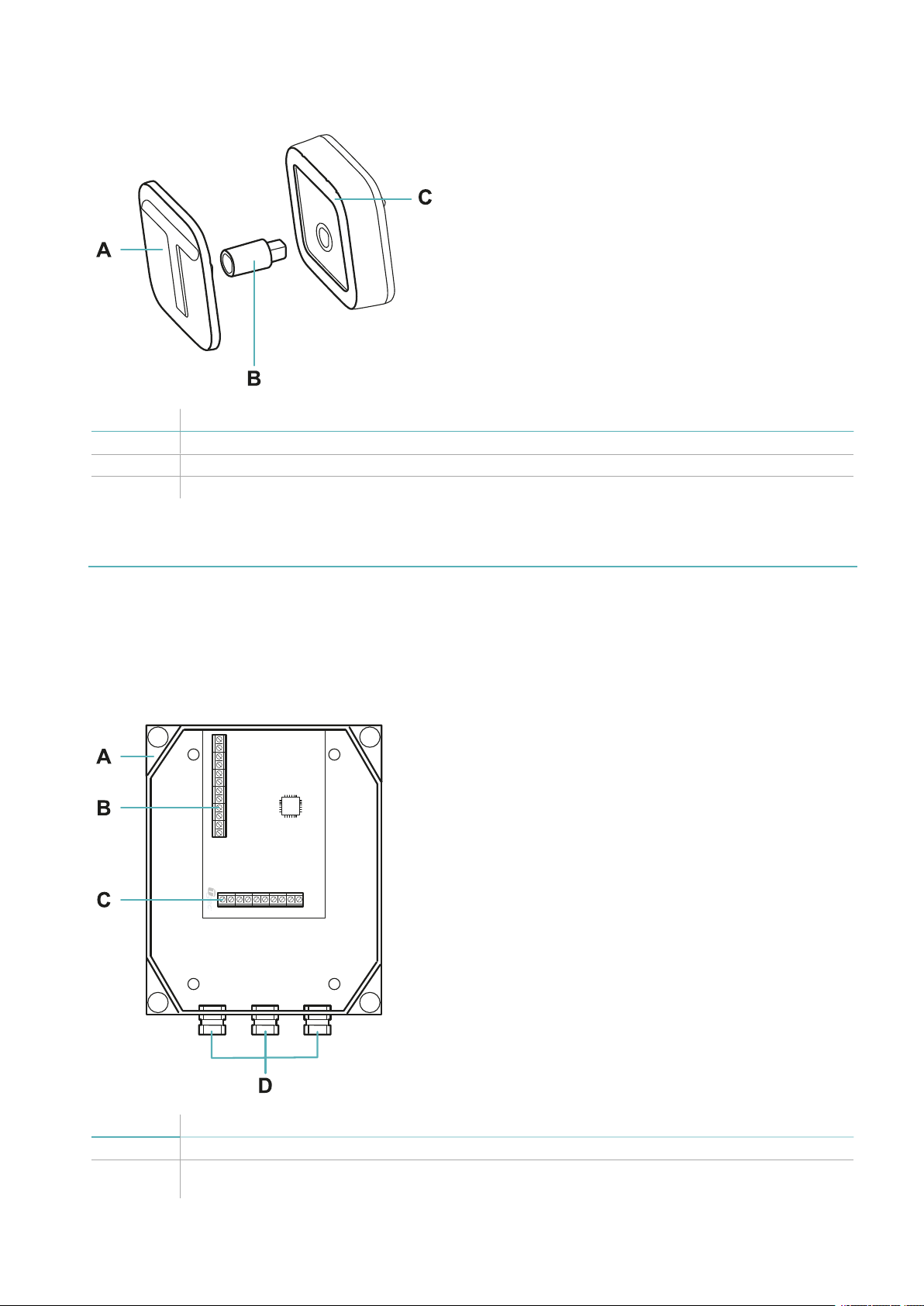
The sensors (MACS-S3H)
Functioning
The sensors detect the vibrations caused by motions of the fence thanks to an accelerometer and send the
signals to the Master via bus. The algorithm recognizes attempts to climb over the fence by filtering out
vibrations caused by accidental impacts or weather.
Sensor front
Part Description
A Sensor body
B Hole for fastening screw to pole or counter- plate
C Bus cables
D T- cap
8
MACS| Instruction manual v1.1 11- 2018 |MACS_in structions_en_v1.1|© 2018 TSec SpA
Sensor back
Part Description
A Counter- plate for panel installation
B Spacer for panel installation with thick mesh
C Rubber fastening gasket
Get to know MACS
The Master (MACS-MAS)
Functions
The Master performs the following functions:
l Manages the sensor chains.
l Transmits signals from the sensors to the Ethernet board.
Main components
Part Description
A Watertight box
B Terminal block for connecting sensor chains (see "Description of terminal block for connecting
sensor chains" on page22)
MACS| Instruction manual v1.1 11- 2018 |MACS_in structions_en_v1.1|© 2018 TSec SpA
9
Get to know MACS
Part Description
C Terminal block for connecting Ethernet board (see "Description of terminal block for connecting
the Ethernet board " on page22)
D Cable glands, for bus cables of the two sensor chains and towards the Ethernet board
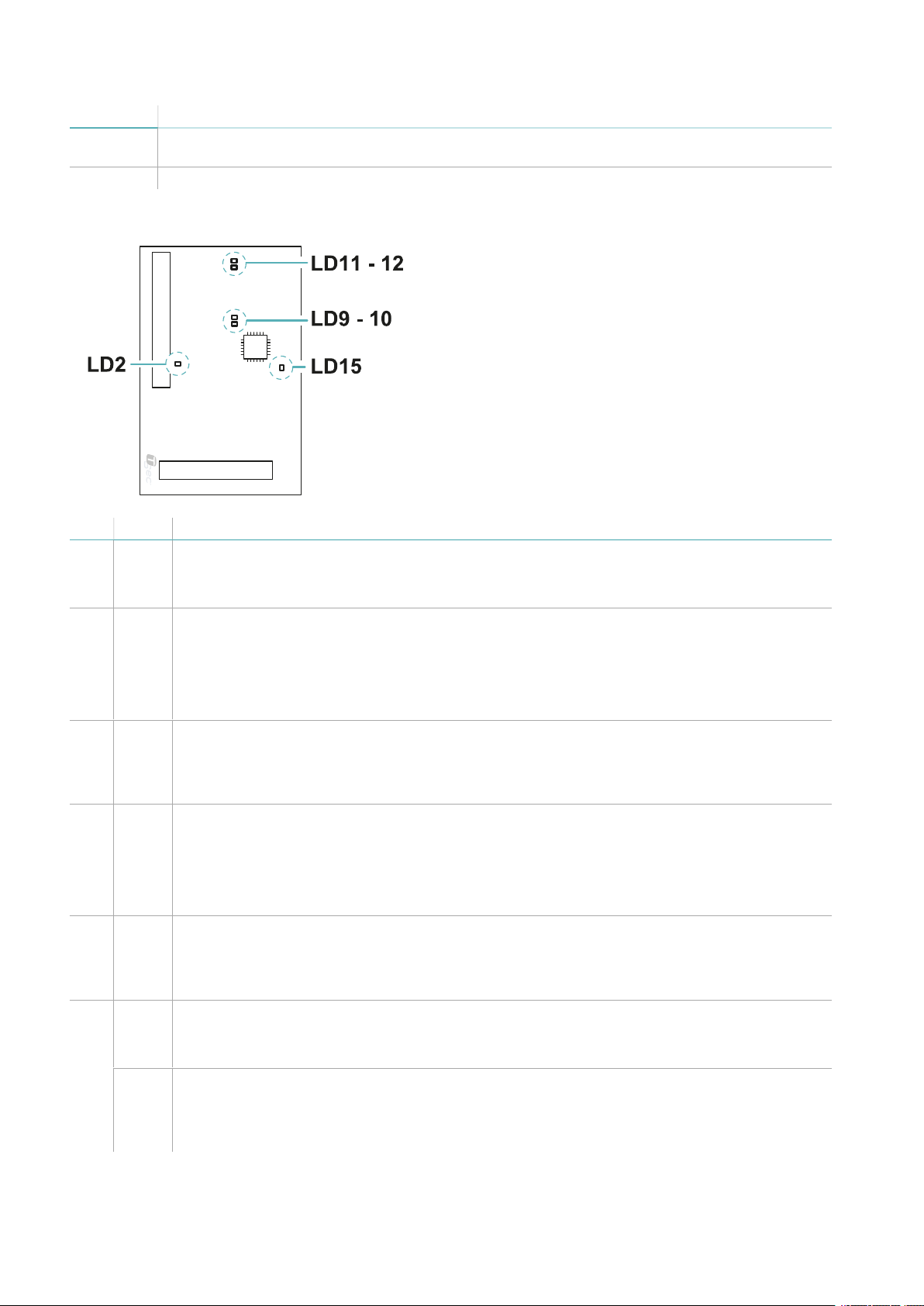
LED
LED Color Description
LD2 Green Power supply status:
l Steady: powered up.
l Off:not powered up (see "LED of the Master" on page31).
LD9 Green Power supply status bus 2:
l Steady: powered up. In the start- up and configuration phase, the LED turns off for a few
seconds and then turns back on.
l Off:not powered up (see "LED of the Master" on page31).
LD10 Red Short- circuit bus 2:
l Steady: short- circuit
l One flashing: short- circuit detected. The Master attempts to power up the bus again and
the LED turns off. If the short- circuit is detected again, the LED turns back on and stays on.
LD11 Green Power supply status bus 1:
l Steady: powered up. In the start- up and configuration phase, the LED turns off for a few
seconds and then turns back on.
l Off:not powered up (see "LED of the Master" on page31).
Red Short- circuit bus 1:
LD12
l Steady: short- circuit
l One flashing: short- circuit detected. The Master attempts to power up the bus again and
the LED turns off. If the short- circuit is detected again, the LED turns back on and stays on.
LD15 Green Firmware status:
10
l Flashing: normal functioning.
l Steady or off: malfunctioning (see "LED of the Master" on page31).
Orange Sensor configuration status:
l Steady: configuration in progress. The sensor alarms are not read. The LED turns off after
about 30 s of inactivity in the web interface.
l Off: configuration concluded.
MACS| Instruction manual v1.1 11- 2018 |MACS_in structions_en_v1.1|© 2018 TSec SpA
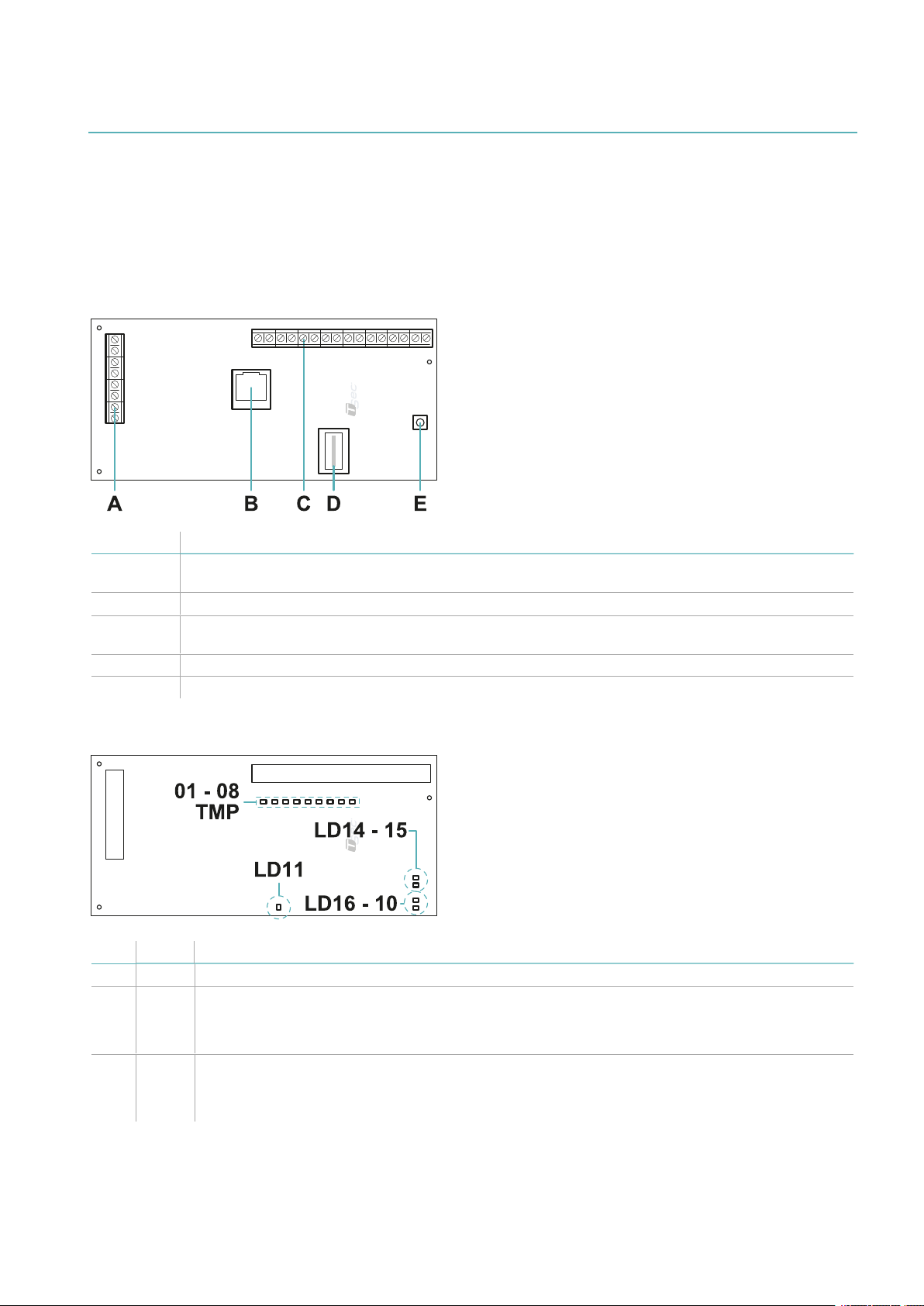
The Ethernet board (MACS-ETH)
Functions
The Ethernet board performs the following functions:
l Powers the other system components.
l Receives signals from the sensors through the Master.
l Signals alarms to the control unit through outputs.
l Allows configuration of the system through the web interface.
Main components
Get to know MACS
Part Description
A Terminal block towards the Master and for system power supply (see "Description of terminal
block towards the Master and for power supply" on page23)
B Ethernet port
C Terminal block towards the alarm control panel (see "Description of terminal block towards the
alarm control panel" on page23)
D Label with serial number of the Ethernet board
E Reset button
LED
LED Color Description
LD10 Red Reset in progress (see "Reset the system" on page31).
LD11 Green Power supply status:
l Steady: powered up.
l Off:not powered up (see "LED of the Ethernet board" on page31).
LD14 Orange Enabled connection option (see "Connection to the Ethernet board " on the next page):
l Steady:through the serial number of the controller and IP address.
l Off: only through IP address.
MACS| Instruction manual v1.1 11- 2018 |MACS_in structions_en_v1.1|© 2018 TSec SpA
11

Get to know MACS
LED Color Description
LD15 Green
Network connection status:
l Rapid flashing: search in progress.
l Single slow flashing: through dynamic IP.
l Double slow flashing: through static IP.
l Off: no connection.
LD16 Green Firmware status:
l Flashing: normal functioning.
l Offor steady:malfunctioning (see "LED of the Ethernet board" on page31).
TMP Orange Tampering:
l Steady and all 01–08 steady: total system fault or error in start- up phase. The system has
encountered faults in the saved configurations.
l Steady and at least one among 01- –08 steady: sensors tampering in the zone(s) indicated
or bus short circuit.
l Off: no tampering.
01-08Orange Climbing alarm:
l All steady: fist start- up or restored factory default settings. The system has no sensors
saved in the memory.
l Steady: climbing alarm from at least one sensor of the indicated zone(s).
l Alternating flashing: system configuration in progress.
l Off: no alarms.
Connection to the Ethernet board
Connection options
Three connection options are available:
l Static IP
l Dynamic IP
l Serial number of the Ethernet board (see "Default settings" below)
The network settings define the enabled connection options and can be modified through the web interface
(see "Manage system settings" on page28).
Consult the network administrator to identify the best configuration.
Default settings
The preset connection options are:
l Static IP: 192.168.0.45
l Controller serial number: printed on the label of the Ethernet board (e.g. macs00000000)
Web interface
Functions
The web interface is used to perform the following functions:
l Configure the sensors.
l Associate the sensors with monitoring zones and alarm outputs.
l Enable/disable the sensors.
l Monitor the system status (sensors, zones, outputs).
l Download the sensor log file.
l Manage the system and network settings.
l Manage the users and relative permissions.
12
MACS| Instruction manual v1.1 11- 2018 |MACS_in structions_en_v1.1|© 2018 TSec SpA
 Loading...