


TSCI Mistral-Air Plus MA-1100 Service manual
Technical Manual
Mistral-Air
®
Plus Warming Unit
MA1100-EU (220-240V~,50/60Hz)
MA1100-US (110-120V~,60Hz)
MA1100-JP (100-110V~,50/60Hz)
INT/R298-EN/1-11/09
Beeldschermweg 6 F
3821 AH Amersfoort
The Netherlands
T: +31(0) 33 450 7250
F: +31(0)33 450 7260
contact@tsci.nl
www.tsci.nl

INT/R298-EN/1-11/09
2

Foreword...................................................................................................5
Disclaimer .................................................................................................5
1 Temperature Management.................................................................6
2 Forced Air Warming...........................................................................6
3 Description of Mistral-Air® Plus warming unit ...................... ........... 7
3.1 The Appliance ........................................................................... 7
3.2 The Control Panel ..................................................................... 8
3.2.1 Extra Options ..................................................................... 9
3.3 The Blankets ............................................................................. 9
4 Preparing the Mistral-Air® Plus warming unit for use....................10
5 Mounting the Mistral-Air® Plus warming unit.................................10
6 User Instructions..............................................................................11
6.1 Connection to Power Supply................................................... 11
6.2 Activate the Unit...................................................................... 11
6.3 Connecting the Blanket ........................................................... 12
6.4 Warming up with the Mistral-Air Plus warming unit................ 12
6.4.1 Temperature settings ....................................................... 12
6.4.2 Temperature Selection..................................................... 12
6.5 Stop Warming ......................................................................... 13
7 Maintenance......................................................................................14
8 Storage and Cleaning.......................................................................14
9 Warnings, Precautions and Symbols..............................................14
10 Contra-indications............................................................................14
11 Safety precautions ...........................................................................15
12 Symbols............................................................................................15
13 General Description of Hardware....................................................19
13.1 Housing ............................................................................... 19
13.2 Top Plate............................................................................. 19
13.3 Heating System ................................................................... 19
13.4 Blower Motor ....................................................................... 19
13.5 Power Supply & Electronic Hardware .................................. 19
14 Safety Systems and Alarms.............................................................20
14.1 General Alarms.................................................................... 20
14.2 Other Safety Features ......................................................... 21
15 Temperature & Temperature Alar m Calibration.............................21
15.1 Temperature Calibration...................................................... 21
15.2 Temperature Alarm Calibration............................................ 23
16 Replacing the Filter..........................................................................24
17 Reset the Hour Meter .......................................................................25
18 Repair Procedures ...........................................................................25
18.1 Routine Maintenance........................................................... 25
19 Troubleshooting...............................................................................26
20 Parts Replacement........................................................................... 28
20.1 Replacing the Hose ............................................................. 28
20.2 Replacing the Fuses............................................................ 28
INT/R298-EN/1-11/09
3

20.3 Replacing the Fan ............................................................... 28
20.4 Replacing the Power Cord................................................... 29
20.5 Record findings at paragraph .............................................. 29
20.6 Replacing the Heater........................................................... 29
21 After S ervice Test Protocols............................................................30
21.1 Control board test................................................................ 30
21.2 Set point temperature test ...................................................30
21.3 Alarm tests .......................................................................... 31
21.4 Electrical safety test............................................................. 32
22 After Service Test Form...................................................................33
22.1 Control Board Test .............................................................. 33
22.2 Set point temperature check................................................ 33
22.3 Alarm tests .......................................................................... 33
22.4 Electrical Safety................................................................... 33
23 Electromagnetic Compatibility........................................................34
23.1 Electromagnetic immunity.................................................... 34
23.2 Electromagnetic Emissions.................................................. 36
23.3 Recommended Separations Distances................................ 37
24 Illustrations.......................................................................................38
24.1 Disassembly of the Mistral-Air® Plus warming unit............... 38
24.2 Assembly of the Mistral-Air® Plus warming unit. .................. 41
24.3 The Power Controller Board (PCB)...................................... 42
24.4 Wiring Diagram.................................................................... 43
25 Spare Parts and Order List..............................................................44
26 Warranty............................................................................................45
27 Specifications...................................................................................46
INT/R298-EN/1-11/09
4

Foreword
Congratulations on your purchase of the Mistral-Air
Warming Unit.
This device was developed with and for users and was built in accordance
to the latest safety standards.
We wish you every success in preventing and controlling hypothermia and
are sure the Mistral-Air
Plus warming unit can help you to do so.
Please read this manual carefully before using the Mistral-Air
warming unit.
If you identify any improvements and/or discover any other applications
during the use of the Mistral-Air
®
products, please let us know.
The Surgical Company International B.V. (TSCI)
®
Plus Forced Air
®
Plus
Disclaimer
All rights reserved. No part of this document may be reproduced or
published, electronically, mechanically, in print, photographic print, on
microfilm or by any other means whatsoever, without the explicit consent of
TSCI.
The content of this document has been compiled with the greatest possible
care and this information can be regarded as reliable. Nevertheless,
TSCI is not liable for any consequences arising from the use of the manual.
TSCI reserves the right to make alterations and improvements to the
device. These cannot yet be described in the instructions. TSCI B.V.
cannot be held liable for the final outcome of the patients’ treatment.
This document contains information that may not be published to third
parties. This document may not be used without the explicit written consent
of TSCI.
These instructions are intended for personnel authorised to work with
and/or service the medical device mentioned in this manual.
INT/R298-EN/1-11/09
5

1 Temperature Management
Hypothermia, an abnormal drop in body temperature, is a threat to human
life. Hospital patients in particular run serious risks if their body temperature
falls below 36 ºC. The risk of hypothermia is particularly high at moments
when they are vulnerable, such as pre-, per-, and post-surgical
interventions. Factors that can contribute to hypothermia include the
duration of the surgical intervention, the location of the wound, the amount
of blood loss, the surface area of the wound, the environmental
temperature and the anaesthetic technique.
2 Forced Air Warming
Forced air warming is a widely used and clinically accepted intervention for
the prevention of hypothermia and/or re-warming of the postoperative
surgical patient. The principle of operation for forced air warming systems
is an electrically powered unit consisting of a fan and heating element that
propels warmed air via a flexible hose to a blanket draped over the patient.
Some configurations allow for the patient to be placed on top of the blanket
or surrounded by a warming tube.
All of these forced air warming systems are intended to distribute warmed
air to the patient in a manner that is safe and effective.
INT/R298-EN/1-11/09
6
3 Description of Mistral-Air® Plus warming unit
The Mistral-Air
preventing patients from getting hypothermic.
The Mistral-Air
Mistral-Air
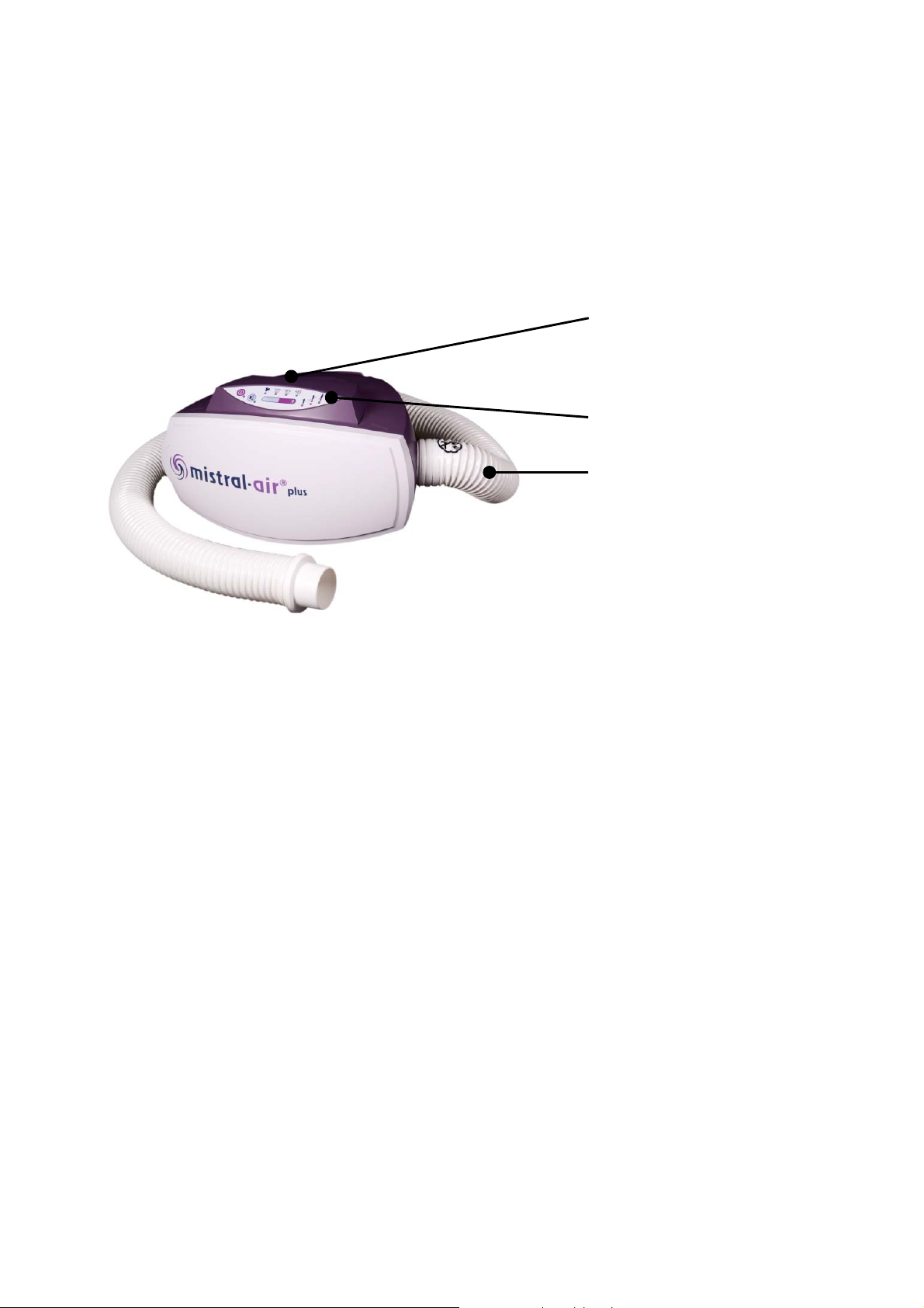
3.1 The Appliance
The Mistral-Air
panel at the front top of the unit. The clamp to fix the Mistral-Air
warming unit to a stand is positioned at the back of the unit.
Article number: - MA1100-EU (220-240V~,50/60Hz)
- MA1100-US (110-120V~,60Hz)
- MA1100-JP (100-110V~,50/60Hz)
®
Plus warming unit is a system which is intended for use in
®
®
blankets that are single patient use only.
Plus warming unit should be used with disposable
®
Plus warming unit can be controlled by using the control
Handle, at top side
Control panel
Hose towards
patient/blanket
®
Plus
INT/R298-EN/1-11/09
7

3.2 The Control Panel
The control panel is located at the front top of the unit and can be
controlled by pressure sensitive buttons.
The Mistral-Air
visible on the control panel and you can select the preferred temperature
by pressing the Temperature Selection button.
In emergencies, an audible alarm will be activated and an L.E.D. will flash
or glow solid red.
Stand-by
button
Explanation of temperature alarm indications:
®
Plus warming unit is very easy to use. All settings are
Temperature Selection
Fan / Ambient air
Indicator
Audible
Alarm
Suppression
button
Temperature
Selection
button
Indicator
Service
Indicator
Under Temp
alarm
Over Temp
alarm
INT/R298-EN/1-11/09
Alarm: An audible alarm is activated and the L.E.D.
flashes or glows red.
- The primary alarm gives a flashing red L.E.D.
- The secondary alarm gives a solid red L.E.D.
Cause: There is an over temperature.
Alarm: The L.E.D. flashes red.
Cause: There is an under temperature.
8
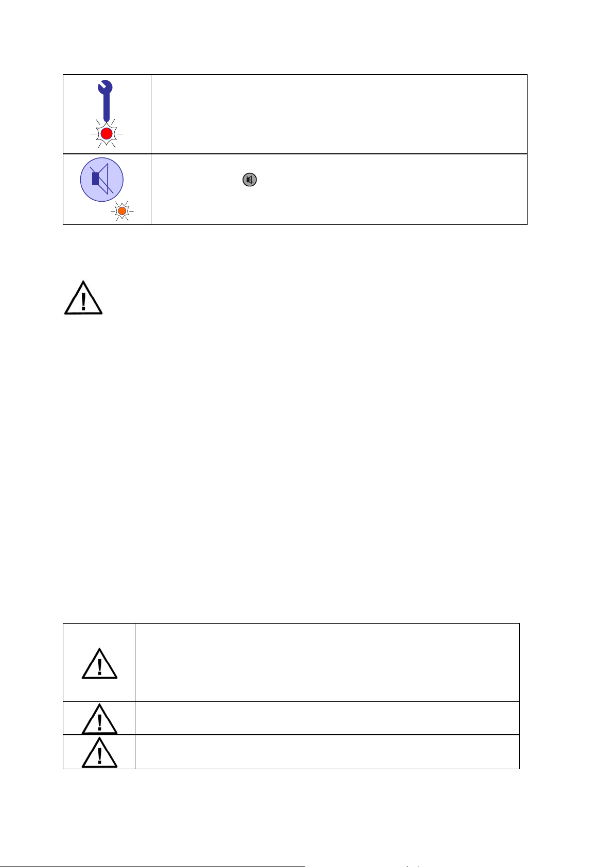
3.2.1 Extra Options
Alarm: The L.E.D. is solid red.
®
Cause: The Mistral-Air
Plus warming unit has been
used for ≥ 500 hours and routine maintenance
is required.
The audible alarm can be suppressed for 3 minutes by
pressing the
button. Audible alarm suppression is
indicated by a solid orange L.E.D. After 3 minutes, the
audible alarm will be activated again.
3.3 The Blankets
Do not use the Mistral-Air
disposables other than Mistral-Air
result.
Mistral-Air
®
blankets come in a variety of designs and sizes to meet the
customers’ needs for preventing and treating hypothermia.
®
All Mistral-Air
blankets are:
®
Plus warming unit with any forced air
®
blankets. Thermal Injury may
Latex free
Made from non-woven polypropylene or polyethylene
Manufactured to meet flammability standards
MR Conditional
Not obstructing x-ray
Non-conductive
Non-sterile, except for several dedicated blankets (ask your distributor)
Packed including an insert in the main languages
Single-patient use only
Made from lightweight, soft materials that have been approved for skin
contact
Mistral-Air
®
blankets need to be used with the soft blue
material towards the patient’s skin and the white or
reflective layer away from the patient’s skin. The blue
side provides the air distribution towards the patient.
Never fold the blankets during use
Thermal injury may occur if heat is applied to ischemic
limbs.
INT/R298-EN/1-11/09
9
4 Preparing the Mistral-Air® Plus warming unit for use
®
Before using the Mistral-Air
should be attached to a stand or placed on a table.
Prior to use, the user needs to check that the Mistral-
®
Plus warming unit, the power cord and the hose
Air
are undamaged. In the event of damage do not
the Mistral-Air
Plug the Mistral-Air
socket.
®
Plus warming unit.
®
Plus warming unit into an earthed
If required, a safety test in accordance with the hospital protocol will follow.
Plus warming unit, it
use
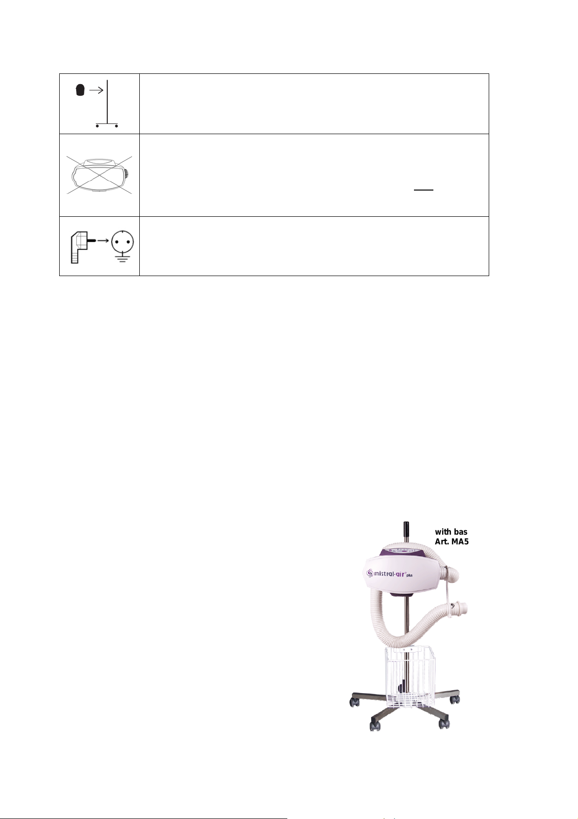
5 Mounting the Mistral-Air® Plus warming unit
The Mistral-Air
The Mistral-Air
pole with basket (art. MA5100-B).
The unit should be clamped onto the pole with the top of the clamp less
than 80 cm above the floor to prevent tipping over.
Avoid blocking the air inlet (bottom of unit)
It is also possible to place the Mistral-Air
not place the unit in the bed with the patient.
®
Plus warming unit must be mounted securely before use.
®
Plus warming unit can be mounted onto the Mistral-Air®
®
Plus warming unit on a table. Do
Mistral-Air®pole
with basket
Art. MA5100-B
INT/R298-EN/1-11/09
10
6 User Instructions
When using the Mistral-Air
be useful.
6.1 Connection to Power Supply
®
Plus warming unit, the instructions below may
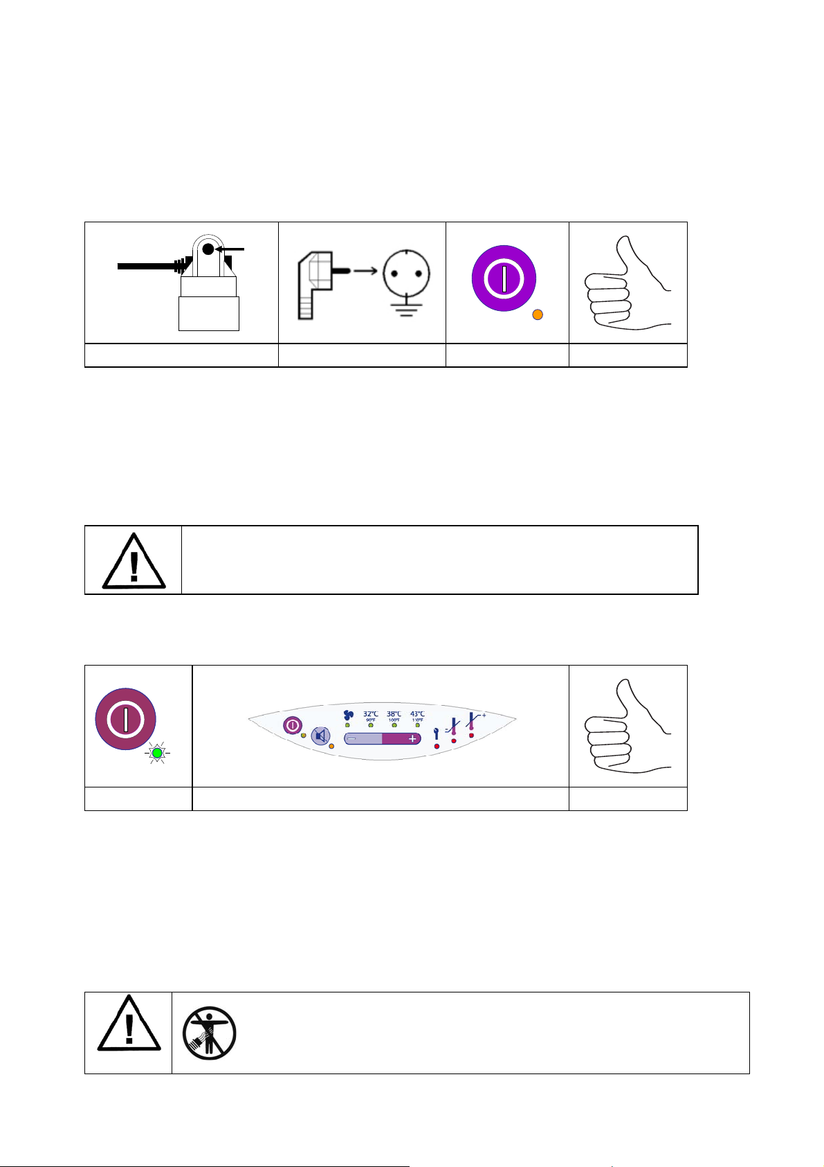
a b c d
a. Make sure the power cord is secured by the cord anchor.
b. Plug the unit into an earthed socket.
c. The unit automatically switches to Stand-by mode, which is indicated by
the orange Stand-by L.E.D.
d. The Mistral-Air
®
Plus warming unit is now in Stand-by mode.
®
To remove all power from the Mistral-Air
Plus warming
unit, the mains power cord must be removed from the
electrical receptacle.
6.2 Activate the Unit
a b c
a. Activate the Mistral-Air
®
Plus warming unit by pressing the Stand-by
button.
b. The Mistral-Air
®
Plus warming unit will now perform a self-test, which
includes a flash of all the L.E.D’s and a short audible alarm.
c. The Mistral-Air
®
Plus warming unit will start blowing air at the default
temperature setting of 38 ˚C.
®
Plus warming unit without
INT/R298-EN/1-11/09
Do not use the Mistral-Air
®
a Mistral-Air
blanket connected to it.
11
6.3 Connecting the Blanket
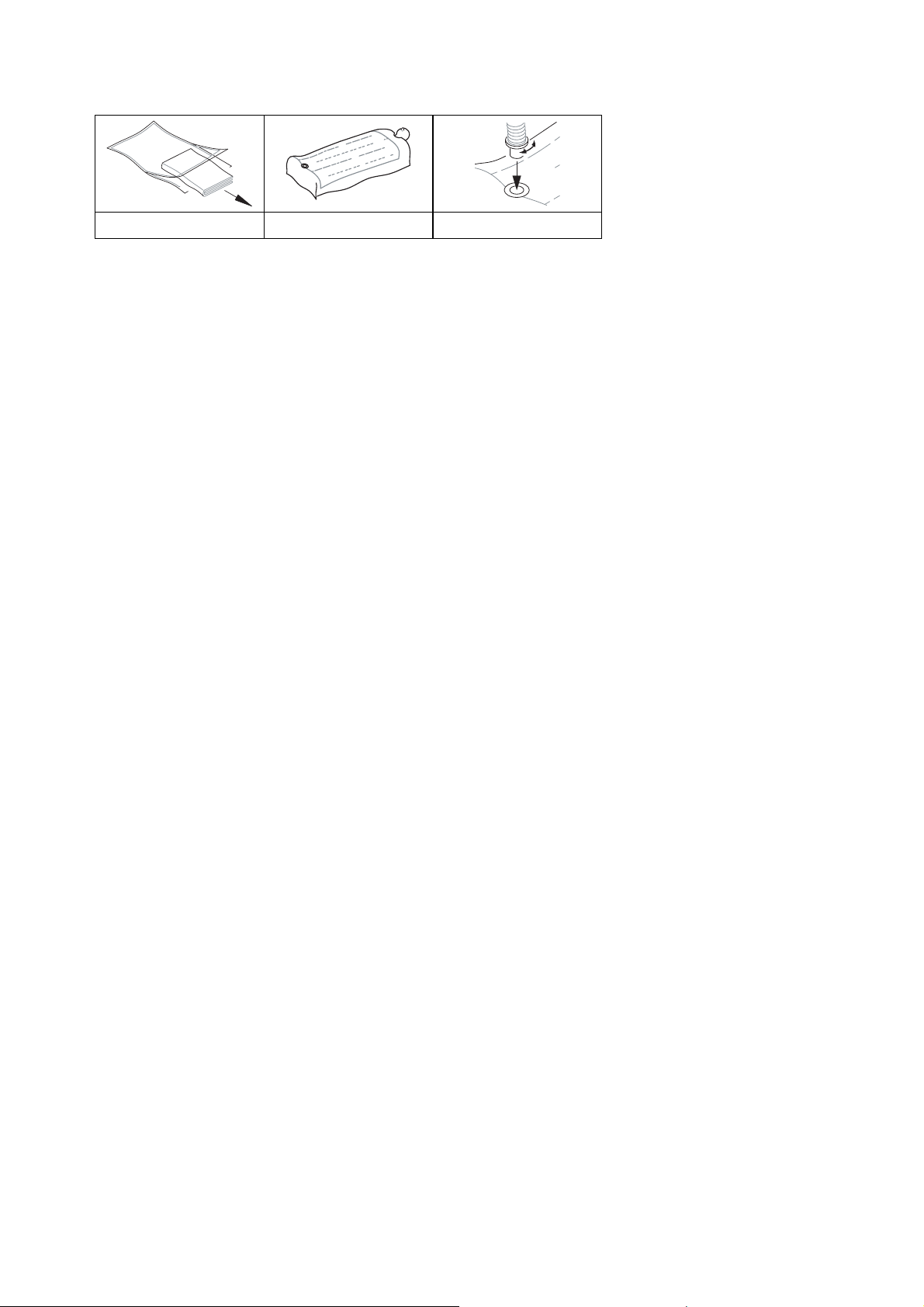
a b c
a. Take the blanket out of the (sterile) package and place it on the patient.
b. Unfold the blanket over the patient.
c. Insert the end of the flexible hose into the air inlet port of the
Mistral-Air
blanket. Make sure the hose is fully pushed in.
Detailed instructions are mentioned on the inserts delivered with the
Mistral-Air
blankets.
6.4 Warming up with the Mistral-Air Plus warming unit
6.4.1 Temperature settings
The four settings are:
Fan - Ambient air
32 ºC - Low temperature
38 ºC - Medium temperature
43 ºC - High temperature
6.4.2 Temperature Selection
The Mistral-Air
®
Plus warming unit will start up with the default temperature
setting of 38 ºC.
By pressing the “–“ button twice, the Mistral-Air
®
Plus will activate the unit
to draw in room temperature air and deliver it to the patient via the blanket.
The heater will not be activated.
The temperature to the patient will depend on ambient conditions and
possible heat from the blower motor.
By pressing the “+” of the temperature selection button the Mistral-Air
®
Plus
will activate the heater to deliver the set temperature: 32 ºC, 38 ºC or 43
ºC.
INT/R298-EN/1-11/09
12
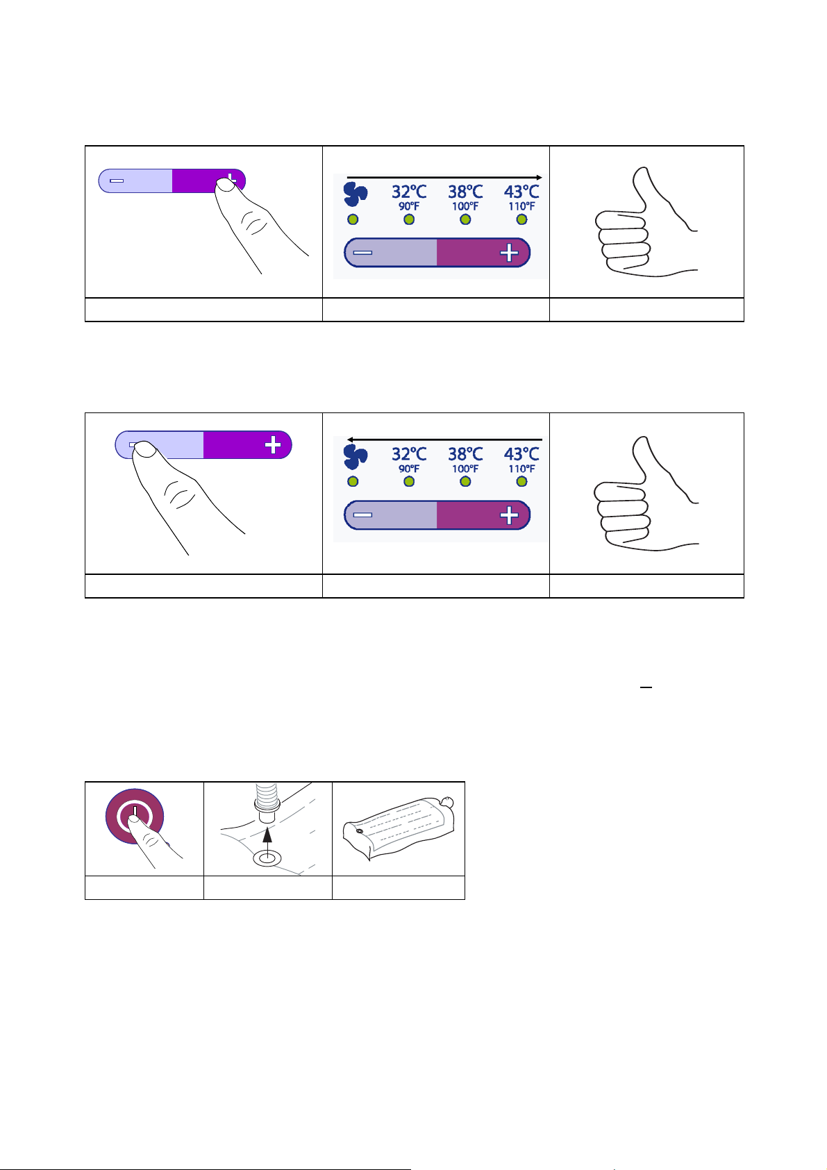
By pressing the “+” of the temperature selecting button, the temperature
setting increases. This is indicated by a green L.E.D.:
a c c
By pressing the “-” of the Temperature Selecting Button, the temperature
setting decreases. This is indicated by a green L.E.D.:
a b c
After selecting the desired temperature, the L.E.D. below the Temperature
Indicator will flash green. After reaching the set temperature (+
2 ˚C) the
flashing L.E.D. will light up permanently.
6.5 Stop Warming
a b c
a. Press the Stand-by button
b. Disconnect the hose from the blanket
c. If desired, leave the blanket on the patient
INT/R298-EN/1-11/09
13

7 Maintenance
The Mistral-Air
users. Users should not repair or open the Mistral-Air
Plus warming unit has no parts that can be maintained by
Plus warming unit in
the event of a malfunction. This can damage the appliance and will
invalidate the guarantee. The hospital service department or the local
supplier should service the Mistral-Air
®
Plus warming unit when the service
indicator is activated or at least once a year.
Have the Mistral-Air
Plus warming unit serial number ready when you
contact the hospital service department or the local supplier for technical
support. The serial number is located on the bottom of the unit.
8 Storage and Cleaning
Store the Mistral-Air
place when not in use.
Clean the unit by wiping the outer surface (including the hose) with a soft
cloth lightly dampened with a solution of water and mild detergent or a nonstaining hospital disinfectant.
Wipe all excess detergent or disinfectant from the unit and allow to air dry.
Do not use alcohol or acid base cleaner on the control panel.
Disconnect from power when cleaning the Mistral-Air
Do not use dripping wet cloths and do not allow water to seep into electrical
areas of the Mistral-Air
Plus warming unit and accessories in a cool and dry
®
Plus warming unit.
Plus warming unit.
9 Warnings, Precautions and Symbols
Your Mistral-Air
mind. The unit should provide reliable service and high quality patient care.
However, there is no replacement for care providers being attentive to their
patients’ needs and equipment operation. Read and understand all
warnings and precautions before using / prescribing the Mistral-Air
warming unit
®
Plus warming unit was designed and built with safety in
®
Plus
10 Contra-indications
Do not apply heat directly to open wounds. All patients’ wounds should be
covered while using the warming system. Do not apply the warming system
to ischemic limbs. Use caution and consider discontinuing use on patients
during vascular surgery when an artery is clamped to an extremity (i.e.
aortic cross-clamping). Use caution and monitor closely if used on patients
with severe peripheral vascular disease.
INT/R298-EN/1-11/09
14