

TSC TTP-2410MU Series, TTP-346MU Series, TTP-2410MT Series, TTP-346MT Series, TTP-644MU Series User Manual
...Page 1

USER’S
MANUAL
TTP-2410MU/ TTP-346MU/ TTP-644MU/
TTP-2410MT/ TTP-346MT/ TTP-644MT Series
THERMAL TRANSFER / DIRECT THERMAL
BAR CODE PRINTER
Page 2

Copyright Information
© 2015 TSC Auto ID Technology Co., Ltd,
The copyright in this manual, the software and firmware in the printer described
therein are owned by TSC Auto ID Technology Co., Ltd, All rights reserved.
CG Triumvirate is a trademark of Agfa Corporation. CG Triumvirate Bold
Condensed font is under license from the Monotype Corporation. Windows is a
registered trademark of Microsoft Corporation.
All other trademarks are the property of their respective owners.
Information in this document is subject to change without notice and does not
represent a commitment on the part of TSC Auto ID Technology Co. No part of
this manual may be reproduced or transmitted in any form or by any means, for
any purpose other than the purchaser’s personal use, without the expressed
written permission of TSC Auto ID Technology Co.
Page 3

- ii -
Agency Compliance and Approvals
EN 55022 (Class A)
EN 55024
EN 61000-3-2 / EN 61000-3-3
EN 60950-1
This is a class A product. In a domestic environment this product may cause radio
interference in which case the user may be required to take adequate measures.
FCC CFR Title 47 Part 15B, Class A
ICES-003, Class A
This equipment has been tested and found to comply with the limits for a Class A
digital device, pursuant to Part 15 of the FCC Rules. These limits are designed to
provide reasonable protection against harmful interference when the equipment is
operated in a commercial environment.
This equipment generates, uses, and can radiate radio frequency energy and, if not
installed and used in accordance with the manufacturer’s instruction manual, may
cause harmful interference with radio communications. Operation of this equipment
in a residential area is likely to cause harmful interference, in which case you will be
required to correct the interference at your own expense.
This Class A digital apparatus complies with Canadian ICES-003.
Cet appareil numérique de la classe A est conform à la norme NMB-003 du
Canada.
AS/NZS CISPR 22 (Class A)
GB-4943.1
GB9254 (Class A)
GB17625.1
此为 A 级产品,在生活环境中,该产品可能会造成无线电干扰,在这种情况下,可
能需要用户对干扰采取切实可行的措施。
UL 60950-1(2nd Edition)
CSA C22.2 No. 60950-1-07(2nd Edition)
EN 60950-1
Page 4

- iii -
Wichtige Sicherheits-Hinweise
1. Bitte lesen Sie diese Hinweis sorgfältig durch.
2. Heben Sie diese Anleitung fűr den späteren Gebrauch auf.
3. Vor jedem Reinigen ist das Gerät vom Stromentz zu trennen. Verwenden Sie keine Flüssig-oder
Aerosolreiniger. Am besten eignet sich ein angefeuchtetes Tuch zur Reinigung.
4. Die Netzanschluß-Steckdose soll nahe dem Gerät angebracht und leicht zugänglich sein.
5. Das Gerät ist vor Feuchtigkeit zu schűtzen.
6. Bei der Aufstellung des Gerätes ist auf sicheren Stand zu achten. Ein Kippen oder Fallen könnte
Beschädigungen hervorrufen.
7. Beachten Sie beim Anschluß ans Stromnetz die Anschlußwerte.
8. Dieses Gerät kann bis zu einer Außentemperatur von maximal 40℃ betrieben werden.
CAUTION
Risk of explosion if battery is replaced by an incorrect type.
Dispose of used batteries according to the instructions.
“VORSICHT”
Explosionsgefahr bei unsachgemäßen Austaush der Batterie. Ersatz nur durch denselben oder
einem vom Hersteller empfohlenem ähnlichen Typ. Entsorgung gebrauchter Batterien nach Angabren
des Herstellers.
CAUTION:
Any changes or modifications not expressly approved by the grantee of this device could void the
user's authority to operate the equipment.
CAUTION
1. HAZARDOUS MOVING PARTS IN CUTTER MODULE. KEEP FINGER AND OTHER
BODY PARTS AWAY.
2. THE MAIN BOARD INCLUDES REAL TIME CLOCK FEATURE HAS LITHIUM BATTERY
CR2032 INSTALLED. RISK OF EXPLOSION IF BATTERY IS REPLACED BY AN
INCORRECT TYPE.
3. DISPOSE OF USED BATTERIES ACCORDING TO THE MANUFACTURER
INSTRUCTIONS.
Page 5

- iv -
Contents
1. Introduction ......................................................................................................................................... 1
1.1 Product Introduction ..................................................................................................................... 1
1.2 Product Features .......................................................................................................................... 2
1.2.1 Printer Standard Features ................................................................................................ 2
1.2.2 Printer Optional Features ................................................................................................. 4
1.3 General Specifications ................................................................................................................. 5
1.4 Print Specifications ..................................................................................................................... 5
1.5 Ribbon Specifications ................................................................................................................... 5
1.6 Media Specifications .................................................................................................................... 6
2. Operations Overview .......................................................................................................................... 7
2.1 Unpacking and Inspection ............................................................................................................ 7
2.2 Printer Overview ........................................................................................................................... 8
2.2.1 Front View .......................................................................................................................... 8
2.2.2 Interior view ..................................................................................................................... 10
2.2.3 Rear View ......................................................................................................................... 11
2.3 Operator Control ......................................................................................................................... 13
2.3.1 LED Indication and Keys ................................................................................................ 15
2.3.2 Touch Screen (MT series) .............................................................................................. 16
3. Setup ................................................................................................................................................ 18
3.1 Setting up the printer .................................................................................................................. 18
3.2 Loading the Ribbon .................................................................................................................... 19
3.2.1 Loading the Ribbon ........................................................................................................ 19
3.2.2 Remove Used Ribbon ..................................................................................................... 22
3.3 Loading the Media ...................................................................................................................... 23
3.3.1 Loading the Media........................................................................................................... 23
3.3.2 Loading the Fan-fold/External Media ............................................................................ 27
3.3.3 Loading Media in Peel-off Mode (Option) ..................................................................... 28
3.3.4 Remove Liner from Internal Rewind (Option) .............................................................. 30
3.3.5 Loading Media in Rewind Liner with Label Mode (Option) ......................................... 31
3.3.6 Remove Labels from Internal Rewind (Option) ............................................................ 32
4. Adjustment Knob .............................................................................................................................. 33
4.1 Print Head Pressure Adjustment knob ....................................................................................... 33
4.2 Print Head Burn Line Adjustment Knob ..................................................................................... 34
Page 6

- v -
4.3 Mechanism Fine Adjustment to Avoid Ribbon Wrinkles ............................................................ 35
5. LCD Menu Function for MT Series ................................................................................................... 37
5.1 Enter the Main Menu ................................................................................................................ 37
5.2 Main Menu Overview ................................................................................................................ 38
5.3 TSPL2 ....................................................................................................................................... 39
5.4 ZPL2 ......................................................................................................................................... 41
5.5 Sensor....................................................................................................................................... 44
5.6 Interface .................................................................................................................................... 45
5.6.1 Serial Comm. .................................................................................................................. 45
5.6.2 Ethernet .......................................................................................................................... 46
5.7 File Manager ............................................................................................................................. 47
5.8 Diagnostics ............................................................................................................................... 48
5.8.1 Print Config. ................................................................................................................... 48
5.8.2 Dump Mode .................................................................................................................... 50
5.8.3 Print Head ....................................................................................................................... 51
5.8.4 Display ............................................................................................................................ 51
5.8.5 Sensor ............................................................................................................................. 51
5.9 Advanced .................................................................................................................................. 52
5.10 Service ...................................................................................................................................... 53
6. LCD Menu Function for MU Series .................................................................................................. 54
6.1 Enter the Main Menu ................................................................................................................ 54
6.2 Main Menu Overview ................................................................................................................ 54
6.3 Setup......................................................................................................................................... 55
6.3.1 Printer Setup (TSPL2/ ZPL2) ......................................................................................... 55
6.3.2 Sensor ............................................................................................................................. 60
6.3.3 Serial Comm. .................................................................................................................. 61
6.3.4 Date Time ........................................................................................................................ 61
6.4 File Manager ............................................................................................................................. 62
6.5 Diagnostics ............................................................................................................................... 63
6.5.1 Print Config. ................................................................................................................... 63
6.5.2 Dump Mode .................................................................................................................... 65
6.5.3 Rotate Cutter .................................................................................................................. 66
6.6 Language .................................................................................................................................. 67
6.7 Service ...................................................................................................................................... 68
7. Diagnostic Tool ................................................................................................................................. 69
Page 7

- vi -
7.1 Start the Diagnostic Tool ............................................................................................................ 69
7.2 Printer Function .......................................................................................................................... 70
7.3 Setting Ethernet by Diagnostic Tool ........................................................................................... 71
7.3.1 Using USB interface to setup Ethernet interface ......................................................... 71
7.3.2 Using RS-232 interface to setup Ethernet interface .................................................... 72
6.3.3 Using Ethernet interface to setup Ethernet interface.................................................. 73
8. Troubleshooting ................................................................................................................................ 75
9. Maintenance ..................................................................................................................................... 78
Revise History ....................................................................................................................................... 79
Page 8

1. Introduction
1.1 Product Introduction
Thank you very much for purchasing TSC bar code printer.
This printer is designed with die-casting aluminum chassis and print mechanism, metal cover with large
clear media view window, which ensuring to work for the extreme and heavy duty industrial environment
and applications.
With back-lit graphic LCD display, printer status can be managed easier and operated more user friendly.
The moveable sensor design can accept wide range of label media. All of the most frequently used bar
code formats are included. Fonts and bar codes can be printed in any one of the four directions.
This printer is built-in the high quality, high performance MONOTYPE IMAGING® True Type font engine
and one CG Triumvirate Bold Condensed smooth font. With flexible firmware design, user can also
download the True Type Font from PC into printer memory for printing labels. Besides the scalable font, it
also provides a choice of five different sizes of alphanumeric bitmap font, OCR-A and OCR-B fonts. By
integrating rich features, it is the most cost-effective and high performance printer in its class!
Applications
o Industrial-duty printing
o Healthcare patient safety
o Compliance labeling
o Work in process
o Order fulfillment
o Distribution
o Shipping/ receiving
o Ticketing
o Electronics & jewelry labeling
Page 9

- 2 -
1.2 Product Features
1.2.1 Printer Standard Features
The printer offers the following standard features.
Product standard feature
203 dpi
models
300 dpi
models
600 dpi
models
Thermal transfer/ or direct thermal
○ ○ ○
High quality die-cast aluminum design
○ ○ ○
Metal cover with large clear media view window
○ ○ ○
Moveable gap sensor (position adjustable)
○ ○ ○
Moveable black mark sensor (position adjustable)
○ ○ ○
Ribbon end sensor
○ ○ ○
Ribbon encoder sensor (Support color ribbon)
○ ○ ○
Head open sensor
○ ○ ○
Graphic type, 128 x 64 pixel, with back light---MU series
Resistive Touch Screen, 16 bits Color, 480 x 272 pixels, with
back lights---MT series
Supported languages:
English
French
German
Spanish
Italian
Traditional Chinese
Simplified Chinese
Japanese
Russian
Polish
○ ○ ○
Control panel with 6 operation buttons
○ ○ ○
Control panel security (TCF)
○ ○ ○
LED indicators
○ ○ ○
Real time clock
○ ○ ○
Internal Ethernet print server (10/100 Mbps) interface
○ ○ ○
USB 2.0 client (High speed mode)
○ ○ ○
Serial RS-232C (2400-115200 bps) interface
○ ○ ○
USB host interface, for scanner or PC keyboard
○ ○ ○
128 MB DDR2 SDRAM memory
○ ○ ○
128 MB FLASH memory
○ ○ ○
SD FLASH card memory expands storage to 32 GB
○ ○ ○
32-bit RISC high performance processor
○ ○ ○
Standard industry emulations right out of the box including
Eltron® and Zebra® language support
○ ○ ○
Internal 8 alpha-numeric bitmap fonts
○ ○ ○
Fonts and bar codes can be printed in any one of the four
directions (0, 90,180, 270 degree)
○ ○ ○
Internal Monotype Imaging® true type font engine with one CG
Triumvirate Bold Condensed scalable font
○ ○ ○
Downloadable fonts from PC to printer memory
○ ○ ○
Page 10

- 3 -
Bar code, graphics/image printing
Supported bar code
Supported
image
1D bar code
2D bar code
BITMAP,
BMP, PCX
(Max. 256
colors
graphics)
Code128 subsets
A.B.C, Code128UCC,
EAN128, Interleave 2
of 5, Code 39, Code
93, EAN-13, EAN-8,
Codabar, POSTNET,
UPC-A, UPC-E, EAN
and UPC 2(5) digits,
MSI, PLESSEY,
China Post, ITF14,
EAN14, Code 11,
TELPEN, PLANET,
Code 49, Deutsche
Post Identcode,
Deutsche Post
Leitcode, LOGMARS
CODABLOCK F
mode,
DataMatrix,
Maxicode, PDF417, Aztec,
MicroPDF417,
QR code, RSS
Barcode (GS1
Databar)
○ ○ ○
Supported code page:
Codepage 437 (English - US)
Codepage 737 (Greek)
Codepage 850 (Latin-1)
Codepage 852 (Latin-2)
Codepage 855 (Cyrillic)
Codepage 857 (Turkish)
Codepage 860 (Portuguese)
Codepage 861 (Icelandic)
Codepage 862 (Hebrew)
Codepage 863 (French Canadian)
Codepage 864 (Arabic)
Codepage 865 (Nordic)
Codepage 866 (Russian)
Codepage 869 (Greek 2)
Codepage 950 (Traditional Chinese)
Codepage 936 (Simplified Chinese)
Codepage 932 (Japanese)
Codepage 949 (Korean)
Codepage 1250 (Latin-2)
Codepage 1251 (Cyrillic)
Codepage 1252 (Latin-1)
Codepage 1253 (Greek)
Codepage 1254 (Turkish)
Codepage 1255 (Hebrew)
Codepage 1256 (Arabic)
Codepage 1257 (Baltic)
Codepage 1258 (Vietnam)
ISO-8859-1: Latin-1 (Western European)
ISO-8859-2: Latin-2 (Central European)
ISO-8859-3: Latin-3 (South European)
ISO-8859-4: Latin-4 (North European)
ISO-8859-5: Cyrillic
ISO-8859-6: Arabic
ISO-8859-7: Greek
ISO-8859-8: Hebrew
ISO-8859-9: Turkish
ISO-8859-10: Nordic
○ ○ ○
Page 11

- 4 -
ISO-8859-15: Latin-9
UTF-8
1.2.2 Printer Optional Features
The printer offers the following optional features.
Product option feature
User
option
Dealer
option
Factory
option
Applicator I/O interface (GPIO)
○
Main board with extended memory ( 512 MB Flash/ 256 MB
SDRAM )
○
Peel-off kit
(Include liner rewind spindle and peel off sensor)
○
Internal rewind kit (Max. 6” OD/ Include label rewind spindle and
label redirect kit)
○
Regular guillotine cutter (Cut on non-adhesive material)
0.06~0.25 mm thickness
○
Rotary heavy duty cutter
paper weight <200g/m2
○
Care label cutter
Media width: 25.4~70 mm
Media thickness: Max. 0.15 mm
Media core ID: 50.8 mm~76.2 mm
Non-print area: 2mm from top of form
○
KP-200 Plus series keyboard
○
KU-007 Plus programmable smart keyboard
○
Bluetooth module (Serial interface)
○
802.11 b/g/n wireless module (Serial interface)
○
Note: Except for the linerless cutter, all regular/heavy duty/care label cutters DO NOT cut on media with glue.
Page 12

- 5 -
1.3 General Specifications
General Specifications
Physical
dimensions
270 mm (W) x 308 mm (H) x 515 mm (D)
Weight
15 kg (33.07 Ibs)
Power
Internal switching power supply
Input: AC 100-240V, 2A, 50-60Hz
Output: DC 24V, 5A, 120W
Environmental
condition
Operation: 5 ~ 40˚C (41 ~ 104˚F), 25~85% non-condensing
Storage: -40 ~ 60 ˚C (-40 ~ 140˚F), 10~90% non-condensing
Environmental
concern
Comply with RoHS, WEEE
1.4 Print Specifications
Print
Specifications
203 dpi
models
300 dpi
models
600 dpi
models
Print head resolution
(dots per inch/mm)
203 dots/inch
(8 dots/mm)
300 dots/inch
(12 dots/mm)
600 dots/inch
(24 dots/mm)
Printing method
Thermal transfer/ or direct thermal
Dot size
(width x length)
0.125 x 0.125 mm
(1 mm = 8 dots)
0.084 x 0.084 mm
(1 mm = 12 dots)
0.042 x 0.042 mm
(1 mm = 24 dots)
Print speed
(inches per second)
Up to 14 ips
(11~14 ips for special
media)
Up to 10 ips
(7-10 ips for special
media)
4 ips
Max. print width
4.09” (104 mm)
Max. print length
1000” (25400 mm)
450” (11430 mm)
100” (2540 mm)
Printout bias
Vertical: 1 mm max.
Horizontal: 1 mm max.
Printing ratio
20%, Full web black bar thickness can’t be greater than 48 dots
height
1.5 Ribbon Specifications
Ribbon Specifications
Ribbon outside diameter
Max. 90 mm
Ribbon length
600 meter long
Ribbon core inside diameter
1” core (25.4 mm)
Ribbon width
25.4 mm ~ 114.3 mm (1”~4.5”)
Ribbon wound type
Ink coated outside or inside
Note: Support color ribbon
Page 13

- 6 -
1.6 Media Specifications
Media Specifications
203 dpi models
300 dpi models
600 dpi models
Label roll capacity
208.3 mm (8.2”) OD
Media alignment
Edge alignment
Media type
Continuous, die-cut, Fan-fold, tag, notched, black mark,
perforated, care label (width less than 3 inch)
Media wound type
Printing face outside wound
Media width
25.4~116mm (1" ~ 4.5")
Media thickness
0.06~0.30 mm (2.3~11.8 mil), max. 300g/m2
Media core diameter
25.4~76.2 mm (1”~3”)
Label length
5~25400 mm
(0.20”~1000”)
5~11,430mm
(0.20”~450”)
5~2540mm
(0.20”~100”)
Label length
(cutter mode)
25.4~4064 mm
(1”~ 160”)
25.4~1854 mm
(1”~73”)
25.4~1016 mm
(1”~40”)
Label length
(peeler mode)
25.4~152.4 mm (1”~6”)
Gap height
Min. 2 mm
Black mark height
Min. 2 mm
Black mark width
Min. 8 mm (0.31”)
Page 14

- 7 -
2. Operations Overview
2.1 Unpacking and Inspection
This printer has been specially packaged to withstand damage during shipping. Please
carefully inspect the packaging and printer upon receiving the bar code printer. Please
retain the packaging materials in case you need to reship the printer. Unpacking the
printer, the following items are included in the carton.
If any parts are missing, please contact the Customer Service Department of your
purchased reseller or distributor.
One printer unit
One Windows labeling software/Windows driver CD disk
One quick installation guide
One power cord
One USB interface cable
Page 15

- 8 -
2.2 Printer Overview
2.2.1 Front View
1. LED indicators
2. LCD display
3. Operation buttons
4. Media view window
5. Paper exit chute
6. Printer cover
2
1
3
4
5
6
For MU series
Page 16

- 9 -
1. LED indicators
2. Touch screen
3. Operation buttons
4. Media view window
5. Paper exit chute
6. Printer cover
2
1
3
4
5
6
For MT series
Page 17

- 10 -
2.2.2 Interior view
1. Ribbon rewind spindle
2. Ribbon release button
3. Print head pressure adjustment knobs
4. Z axis mechanism adjustment knob
5. Ribbon tension adjustment knob
6. Print head release lever
7. Media sensor lock lever
8. Ribbon supply spindle
9. Media guide bar & Rear label guide
10. Label roll guard
11. 3” label supply spindle
12. External label entrance chute
13. Damper
14. Print head
15. Platen roller
16. Media sensor
17. Front label guide
2
1
3
4
13
7 5 8 9 10
11
12 6 14
15
16
17
Page 18

- 11 -
2.2.3 Rear View
* Recommended SD card specification
Type
SD card spec
SD card capacity
Approved SD card manufacturer
SDHC
V2.0 Class 4
2G
Transcend
V3.0 Class 10
32G
Kingston
V3.0 Class 10
16G
Kingston
V2.0 Class 4
8G
Scandisk
V3.0 Class 10
32G
Scandisk
1. External label entrance chute
2. Power cord socket
3. Power switch
4. Ethernet interface
5. * SD card socket
6. USB interface
7. USB host
8. RS-232C interface
9. GPIO interface (Option)
10. Centronics interface
Note:
The interface picture here is for reference only. Please refer to the product
specification for the interfaces availability.
1
3
2
4
7
6
5
8
9
10
Page 19

- 12 -
Micro SD
V2.0 Class 4
4G
Transcend
V2.0 Class 4
8G
Transcend
V3.0 Class 10 UHS-I
16G
Transcend
V3.0 Class 10 UHS-I
32G
Transcend
V3.0 Class 10
16G
Kingston
V2.0 Class 4
16G
Scandisk
V3.0 Class 10 UHS-I
16G
Scandisk
- The DOS FAT file system is supported for the SD card.
- Folders/files stored in the SD card should be in the 8.3 filename format.
- The miniSD/microSD card to SD card slot adapter is required.
Page 20

- 13 -
2.3 Operator Control
For MU series
LEDs
LCD
display
Keys
Printer
model
Printer firmware
version
Page 21

- 14 -
For MT series
LEDs
Touch
screen
Keys
Icons
Printer
model
Printer firmware
version
Page 22

- 15 -
2.3.1 LED Indication and Keys
LED
Status
Indication
POWER
Off
Printer power off
On
Printer power on
ON-LINE
On
Printer is ready
Blinking
Printer is paused
Printer is downloading data
ERROR
Off
Printer is ready
On
Carriage open or cutter error
Blinking
No paper, paper jam or no ribbon
Keys
Function
PAUSE
Pause/Resume the printing process
MENU
1. Enter the menu
2. Exit from a menu or cancel a setting and return to the previous menu
FEED
Advances one label
UP
Scroll up the menu list
SELECT
Enter/Select cursor located option
DOWN
Scroll down the menu list
Page 23

- 16 -
2.3.2 Touch Screen (MT series)
Tap an item to open/use it.
Be selected
(Red)
Return
Next page
Up page
Scroll down
Scroll up
Page 24

- 17 -
Set
Page 25

- 18 -
3. Setup
3.1 Setting up the printer
1. Place the printer on a flat, secure surface.
2. Make sure the power switch is off.
3. Connect the printer to the computer with the provided USB cable.
4. Plug the power cord into the AC power cord socket at the rear of the printer, and then plug the power
cord into a properly grounded power outlet.
Note: Please switch OFF printer power switch prior to plug in the power cord to printer power
jack.
Page 26

- 19 -
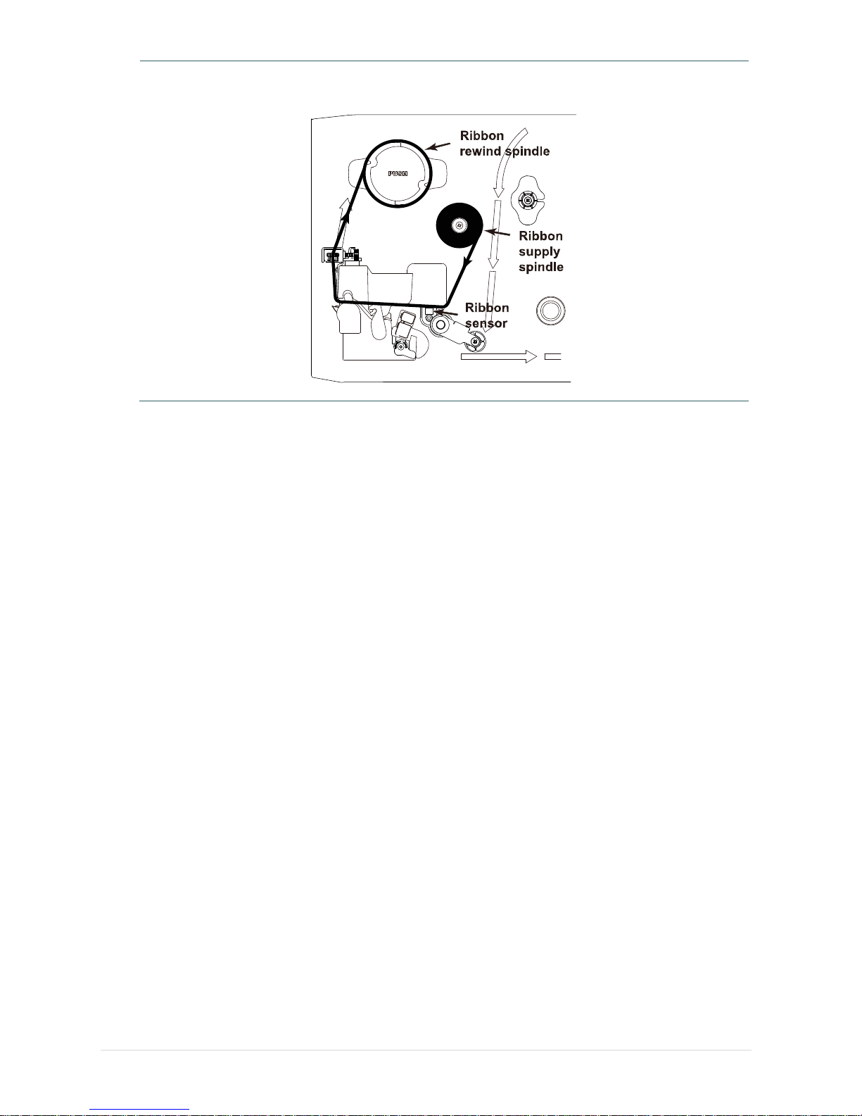
3.2 Loading the Ribbon
3.2.1 Loading the Ribbon
1. Open the printer right side cover.
2. Push the print head release lever to
open the print head mechanism.
3. Install the ribbon onto ribbon supply
spindle.
Page 27

- 20 -
4. Thread the ribbon through the ribbon
sensor slot and then through the open
space in between print head and
platen.
5. Wrap the ribbon onto the ribbon
rewind spindle. Wind the ribbon
clockwise about 3~5 circles onto the
ribbon rewind spindle until it is smooth
and properly stretched.
Note: Please DO NOT push the ribbon
release button when you are
loading the ribbon. The ribbon
release button is used to remove
the used ribbon.
6. Close the print head mechanism,
Make sure the latches are engaged
securely.
Note:
Please refer to video on TSC YouTube
or driver CD.
Ribbon
sensor
Page 28
- 21 -
Loading path for ribbon
Page 29
- 22 -
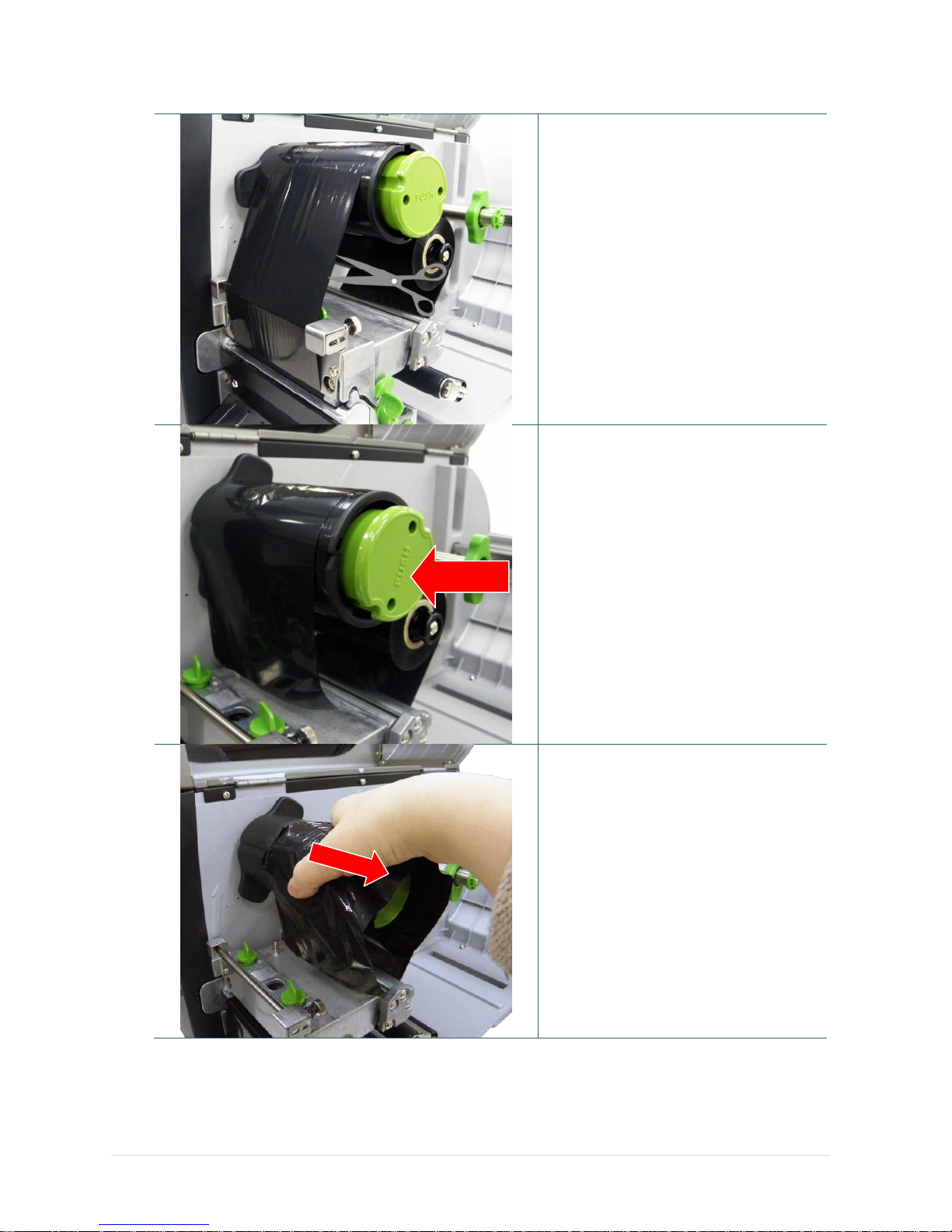
3.2.2 Remove Used Ribbon
1. Break the ribbon between ribbon
guide plate and the ribbon rewind
spindle.
2. Push the ribbon release button to
release the ribbon on the ribbon
rewind spindle.
3. Slide off the ribbon from ribbon rewind
spindle.
PUSH
Page 30
- 23 -
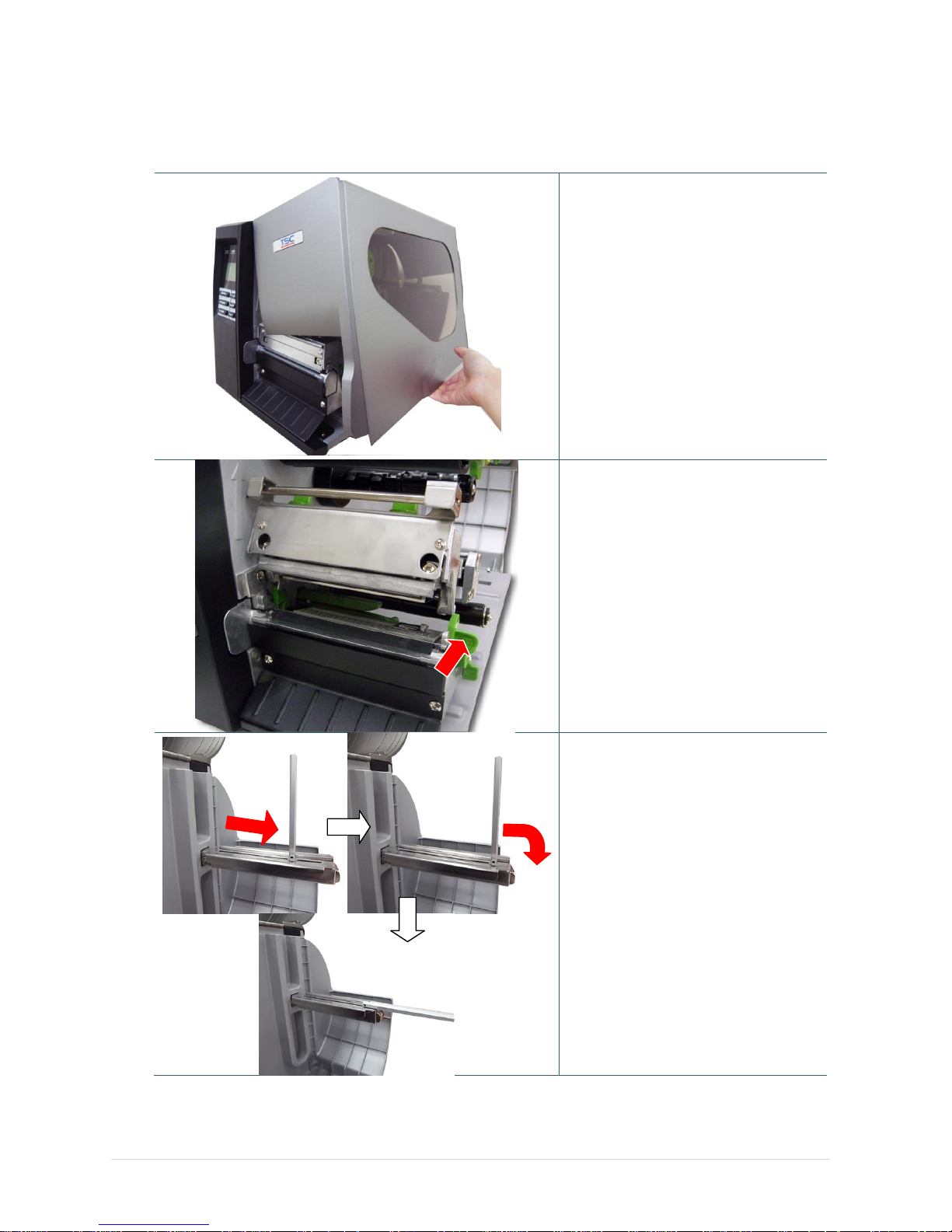
3.3 Loading the Media
3.3.1 Loading the Media
1. Open the printer right side cover.
2. Push the print head release lever
to open the print head mechanism.
3. Move the label roll guard
horizontally to the end of label
spindle then flip down the label roll
guard.
Page 31
- 24 -
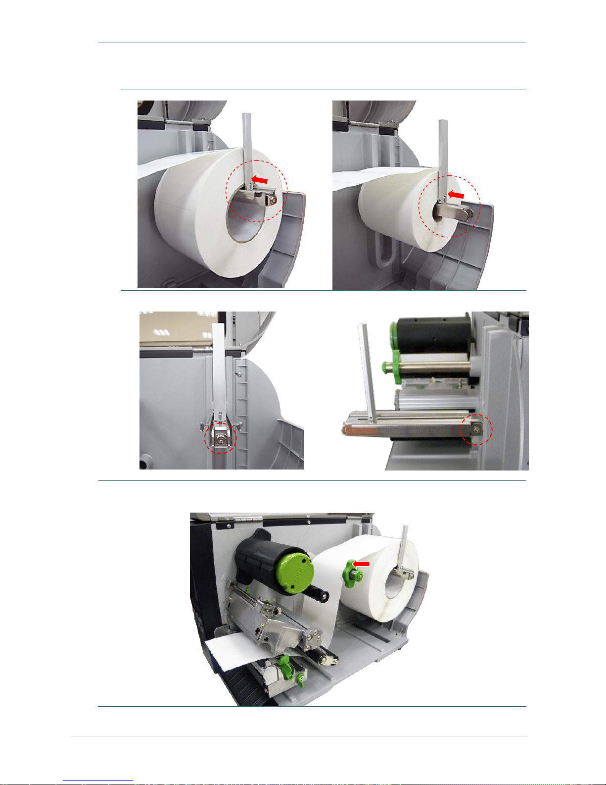
4. Place the roll of media on the label supply spindle. Flip up the label roll guard. Move the label roll
guard horizontally to gently fit the width of label roll.
3” core label spindle
1” core label spindle
Replace 3” core label spindle module to fit the 1” core label by removing two screws.
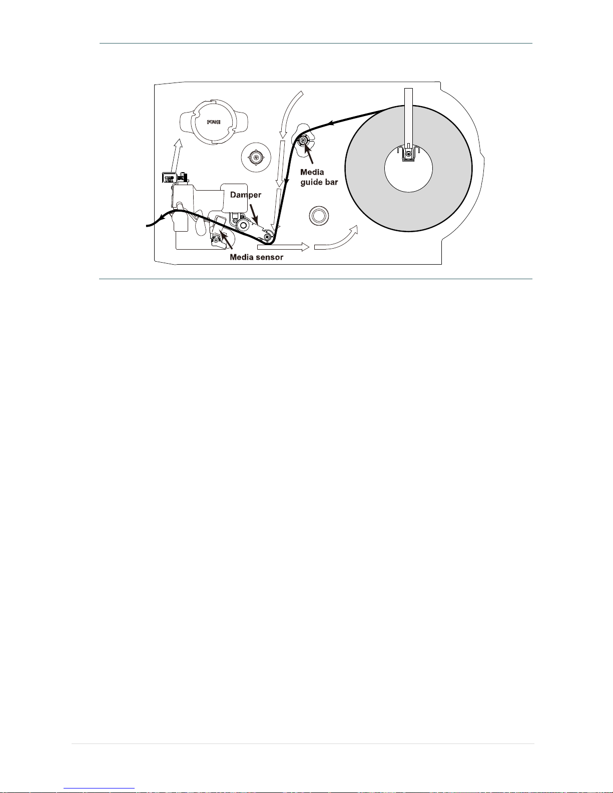
5. Pull label roll leading edge forward through the media guide bar, damper, media sensor (green)
and place the label leading edge onto the platen roller. Adjust the rear label guide (green) to fit
the width of the label.
Rear label
guide
Page 32
- 25 -
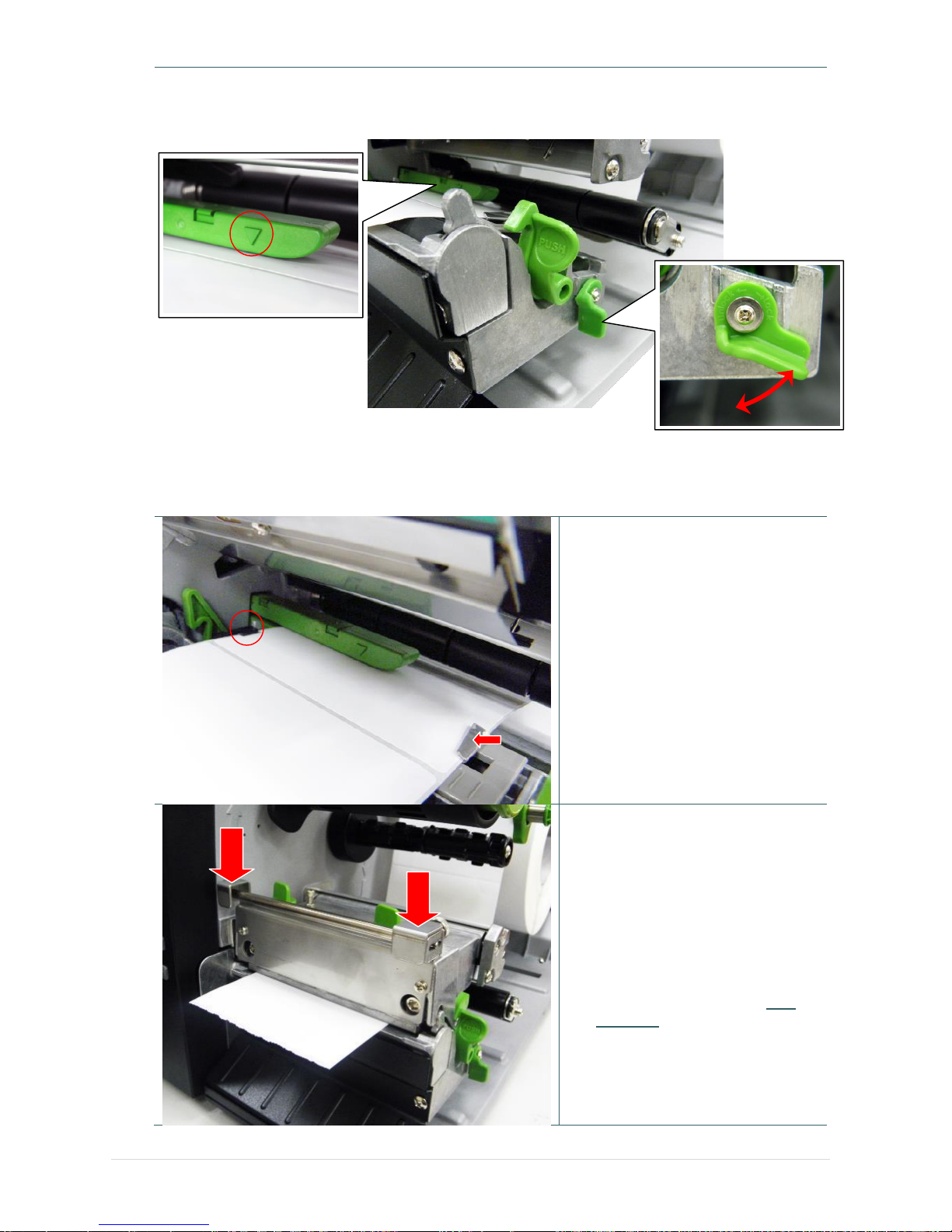
6. Unlock the media sensor lock lever to adjust the media sensor, make sure the gap or black mark
sensor is at the location where media gap/black mark will pass through for sensing.
Note:
* The sensor location is marked by a triangle mark ▽ at the sensor housing.
* The media sensor position is moveable, please make sure the gap or black mark is at the
location where media gap/black mark will pass through for sensing.
7. Adjust front label guide to fit the
width of the label.
8. Close the print head mechanism.
Make sure the latches are
engaged securely.
9. Using the front display panel, set
media sensor type and calibrate
the selected sensor.
Note:
* Please calibrate the gap/black
mark sensor when changing
media.
* Please refer to video on TSC
YouTube or driver CD.
Lock
Unlock
Front label
guide
Page 33
- 26 -
Loading path for media
Page 34
- 27 -
3.3.2 Loading the Fan-fold/External Media
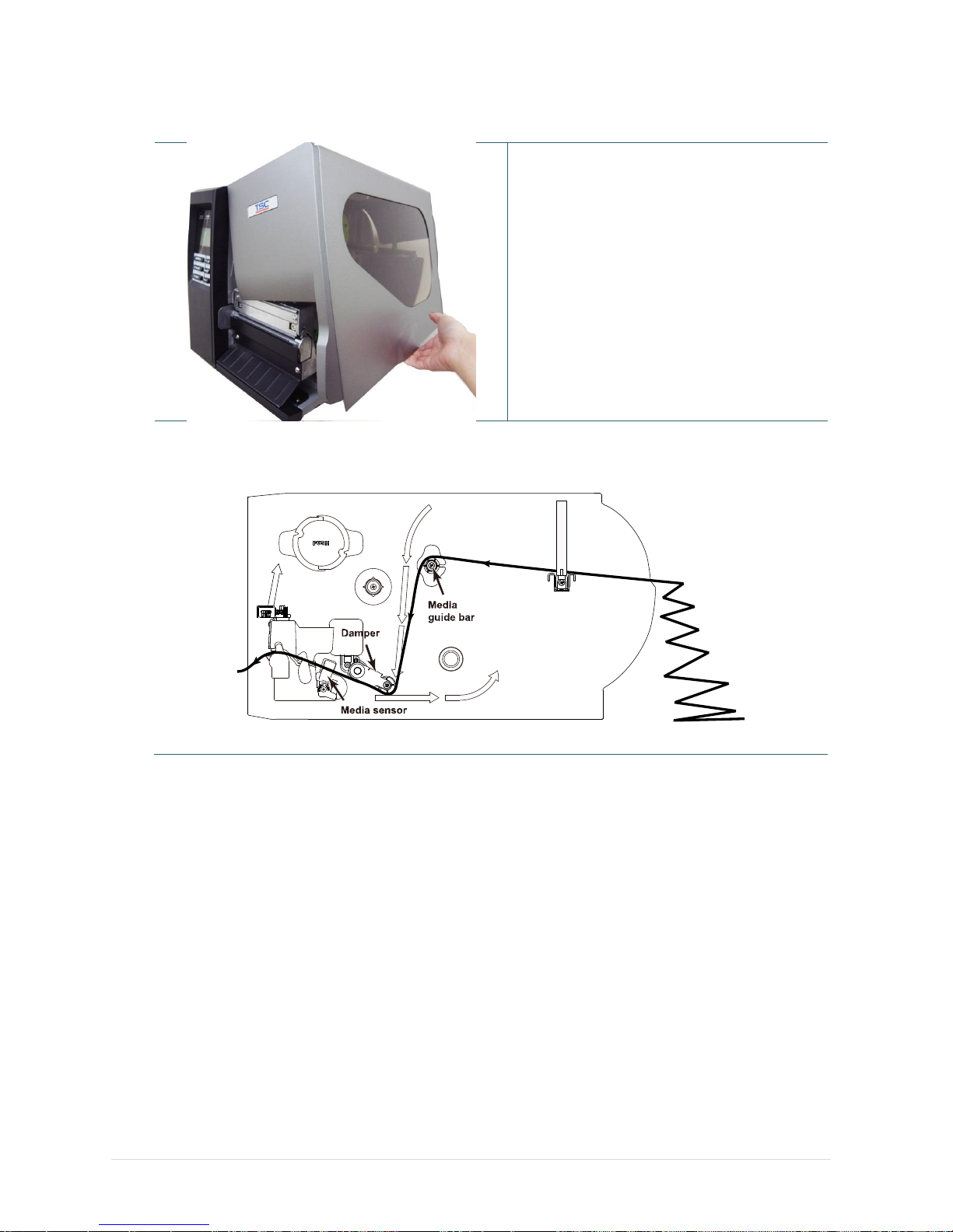
1. Open the printer right side cover.
2. Insert the fan-fold media through the
bottom or rear external label entrance
chute.
3. Please refer to section 3.3.1 to loading
media.
Note:
Please calibrate the gap/black mark
sensor when changing media.
Loading path for fan-fold labels
Page 35
- 28 -
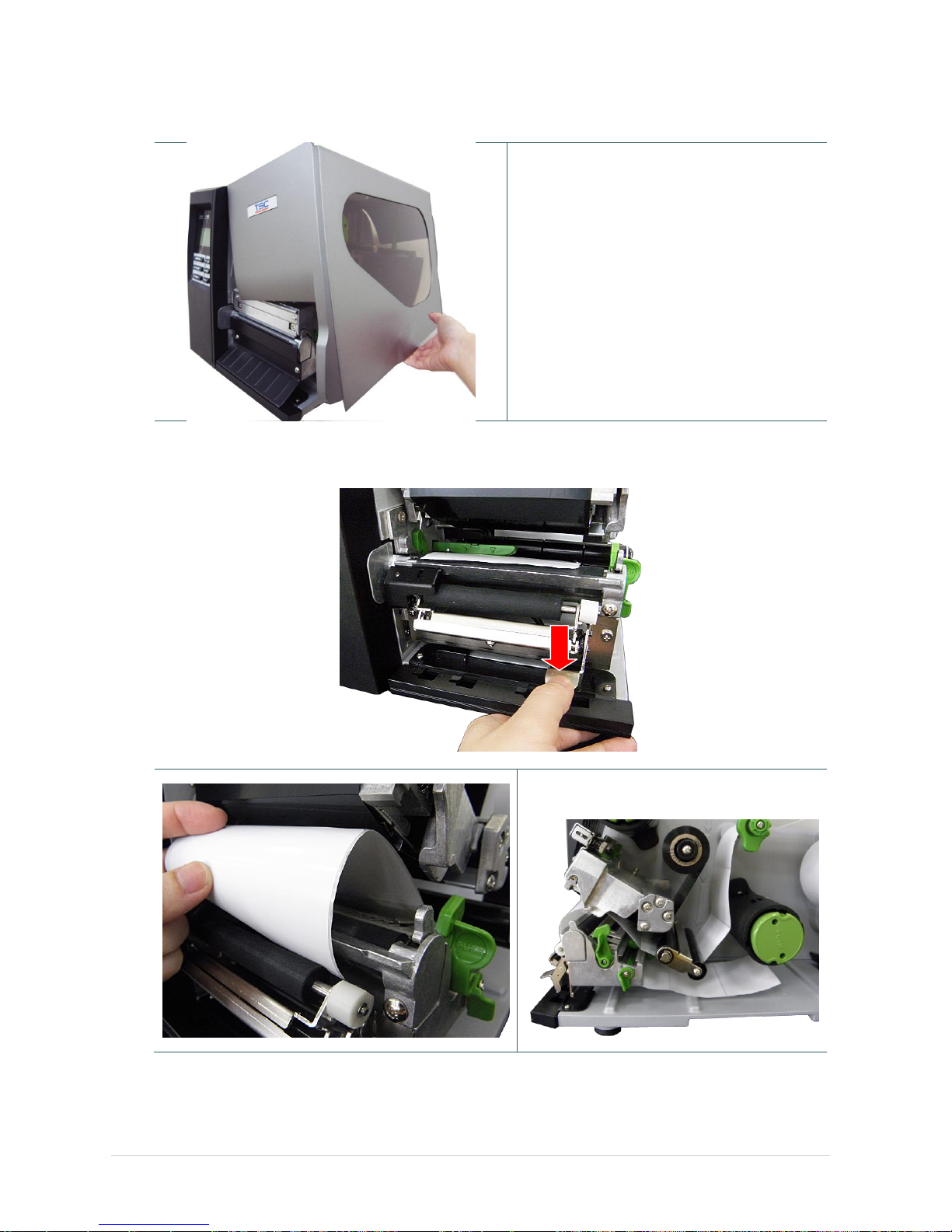
3.3.3 Loading Media in Peel-off Mode (Option)
1. Open the printer right side cover.
2. Please refer to section 3.3.1 step 3~9 for
loading media.
3. Using the front display panel to do the
calibration first and set the printer mode to
peeler mode.
Note:
Please calibrate the gap/black mark
sensor before loading media in peel-off
mode to avoid paper jam.
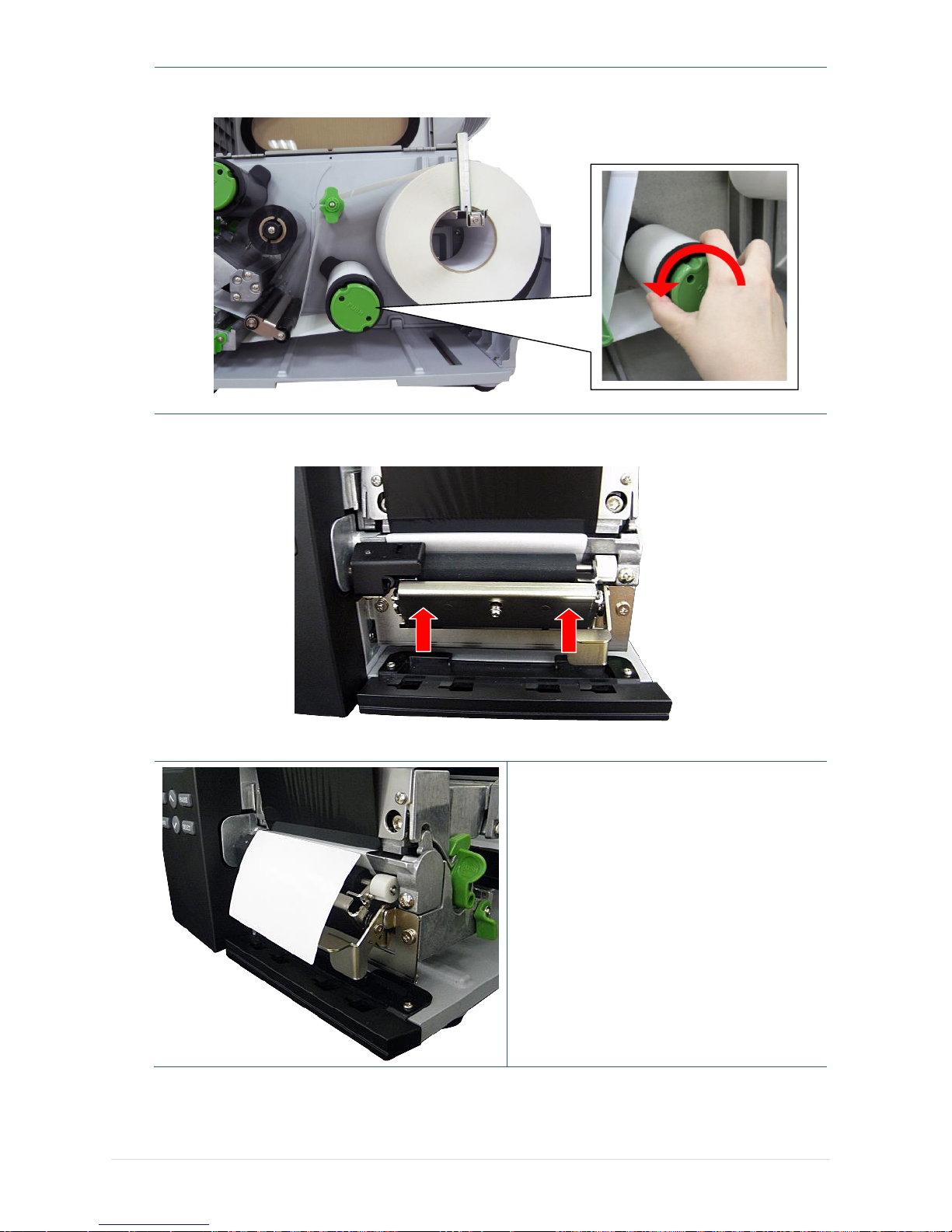
4. Open print head release lever to pull approximately 650mm of label through the front of the
printer.
5. Push down the peel-off roller release lever.
6. Feed the label between peel-off roller
and platen roller.
Peel-off roller
Page 36
- 29 -
7. Wrap the label onto the internal rewind spindle and wind the spindle counter-clockwise about 3~5
circles until the label is properly stretched.
8. Lift up the peel-off roller release lever and close the print head mechanism.
9. Peeling will automatically start. Press the
FEED button to test.
PUSH
PUSH
Page 37
- 30 -
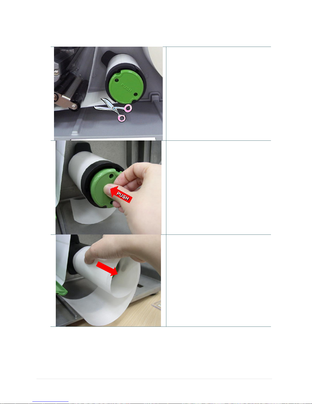
3.3.4 Remove Liner from Internal Rewind (Option)
1. Break the liner between peel-off roller and
the internal rewind spindle.
2. Push the liner release button to release the
liner on the internal rewind spindle.
3. Slide off the liner from internal rewind
spindle.
Page 38
- 31 -
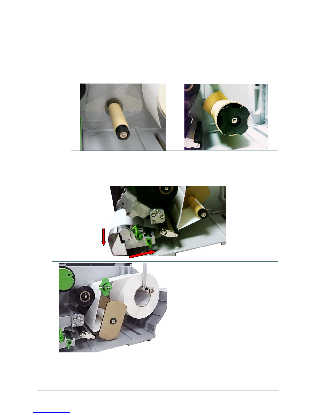
3.3.5 Loading Media in Rewind Liner with Label Mode (Option)
This mode can rewind the media including liner and label on the rewind spindle
1. Open the printer right side cover and the print head mechanism.
2. Insert the supply holder guide and paper core into the internal rewind for 1” core label roll. Insert
the supply holder guide, 3” label core adapter and paper core into the internal rewind for 3” core
label roll.
1” core label roll
3” core label roll
3. Insert media into the printer label spindle. Pull label roll leading edge forward through the media
guide bar, damper media sensor and place the label leading edge onto the platen roller.
4. Pull approximately 650mm of label through the label redirect front panel.
5. Wrap the label onto the internal rewind spindle and stick the label onto the paper core.
6. Insert another supply holder guide into
the internal rewind for 1” core label roll.
7. Close the print head mechanism.
8. Using the LCD panel to set the media
sensor type and calibrate the selected
sensor.
Page 39
- 32 -
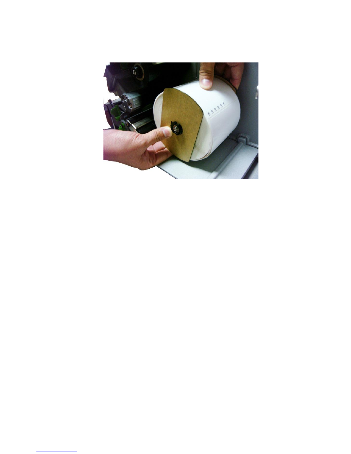
3.3.6 Remove Labels from Internal Rewind (Option)
1. Slide off the labels with supply holder guides from internal rewind spindle.
Supply holder
guides
Page 40
- 33 -
4. Adjustment Knob
4.1 Print Head Pressure Adjustment knob
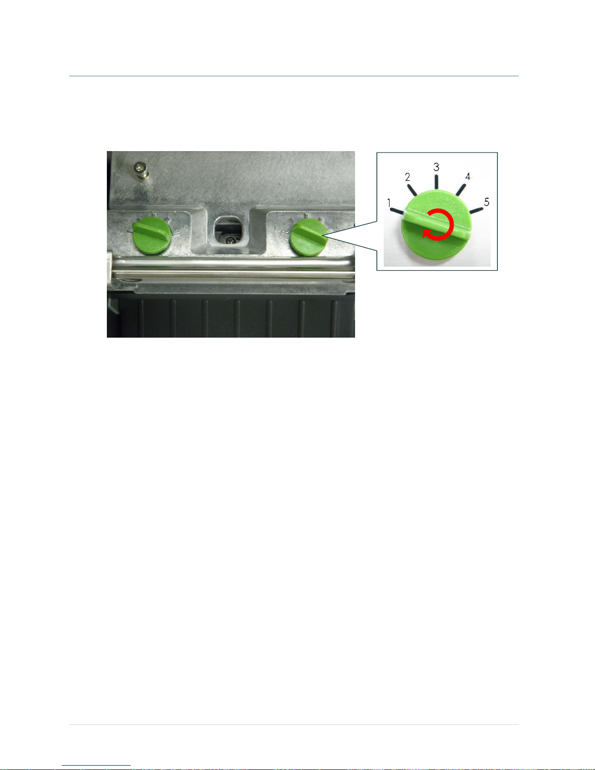
The print head pressure adjustment knob has 5 levels of adjustment. Because the printer’s paper
alignment is to the left side of mechanism, different media widths require different pressure to print
correctly. Therefore it may require to adjust the pressure knob to get your best print quality. For
example, if the label width is 4”, adjust both print head pressure adjustment knobs to the same level. If
the label is less than 2” wide, increase the left side print head pressure by rotating the adjustment knob
clockwise and decrease the right side pressure by rotating the adjustment knob counter-clockwise to
level 1.
Page 41
- 34 -
4.2 Print Head Burn Line Adjustment Knob
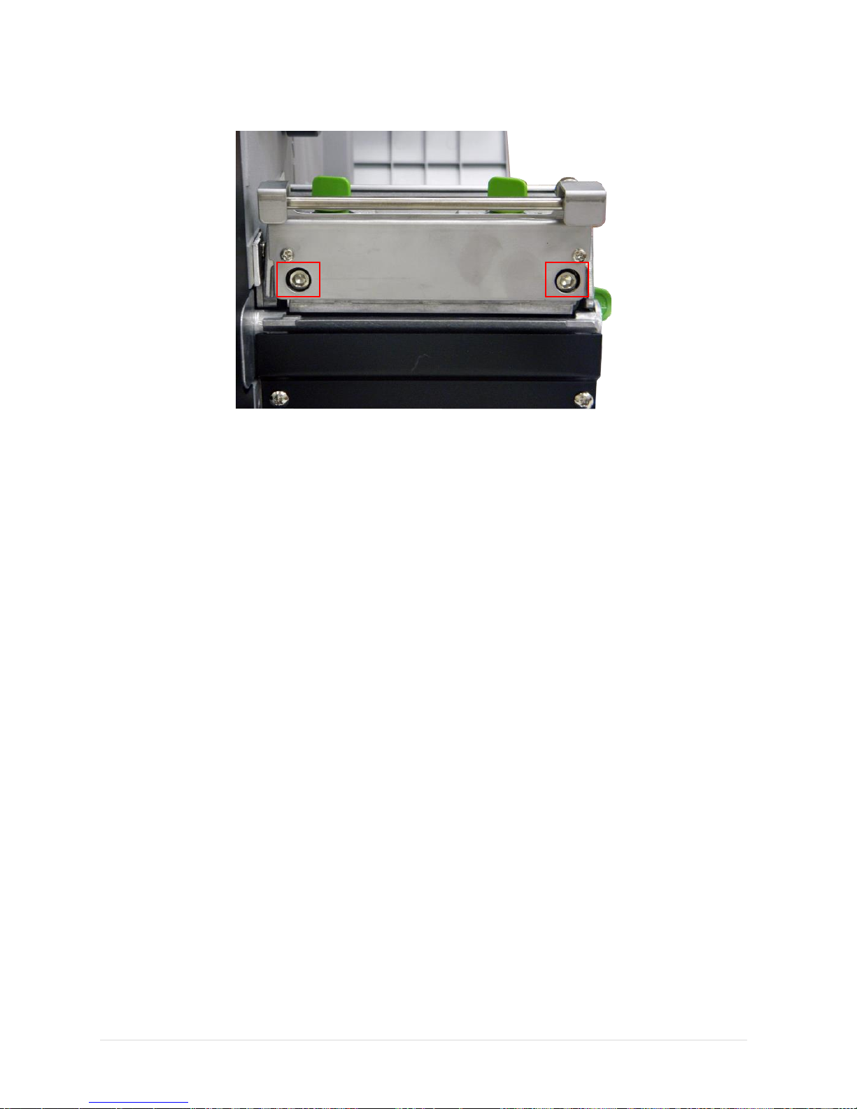
The print head burn line adjustment knobs are used to fine tune the print quality for different thickness
of media. Turning the knobs adjusts the print head’s burn line forward or backward as it relates to the
platen roller.
The print head burn line default is set for general purpose printing media (plain paper and paper
thickness less than 0.20mm). In general using, it does not need to adjust the print head burn line. If you
have poor print quality, please modify the printer density or adjust the print head pressure adjustment
knob, or adjust z-axis mechanism first.
Caution:
Incorrectly adjusting print head burn line adjustment knobs can lead to poor print quality and
may cause damage to the printer. Proceed with caution.
Poor print quality when using paper thicker than 0.20mm may be due to the print head burn line not
being at the optimized position. To improve the print quality, increase the head pressure or adjust the
knobs counter-clockwise to move print head burn line toward the paper out direction then print again.
Continue to adjust the burn line position and test print as necessary until the printout image is clear.
Page 42
- 35 -
4.3 Mechanism Fine Adjustment to Avoid Ribbon Wrinkles
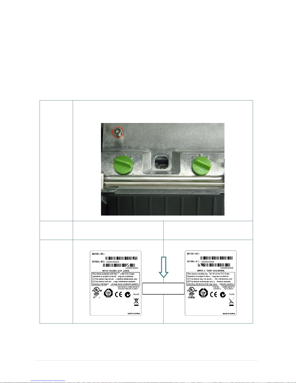
This printer has been fully tested before delivery. There should be no ribbon wrinkle presented on the
media for general-purpose printing application. Ribbon wrinkle is related to the media thickness, print
head pressure balance, ribbon film characteristics, print darkness setting…etc. In case the ribbon wrinkle
happens, please follow the instructions below to adjust the printer parts.
Adjustable
Printer
Parts
The print head pressure adjustment knob has 5 levels of settings. Clockwise direction
adjustment is to increase the print head pressure. Counter Clockwise adjustment can
decrease the print head pressure.
Symptom
1. Wrinkle happens from label lower
left to upper right direction (“ˊ”)
2. Wrinkle happens from label lower
right to upper left direction (“ˋ”)
Wrinkle
Example
Feed direction
Z-axis mechanism
adjustment knob
Print head pressure
adjustment knob
Page 43

- 36 -
The print head pressure adjustment knob
has 5 levels of settings. Clockwise direction
adjustment is to increase the print head
pressure. Counter Clockwise adjustment
can decrease the print head pressure.
If the wrinkle on the label starts from the
lower left side to upper right side, please do
following adjustment.
1. Decrease the right side print head
pressure adjustment knob setting 1 level
per each adjustment then print the label
again to check if wrinkle is gone.
2. If the right side print head adjustment
knob setting has been set to index 1 (the
lowest pressure index), please increase
the left side print head pressure.
3. If the left side print head adjustment knob
setting has been set to 5 (the highest
pressure index) the wrinkle can’t be avoid,
please rotate the both knobs back to
setting 1 then rotate the Z-axis
mechanism adjustment knob clockwise for
a few degrees and print again for fine tune
the print head pressure distribution.
Note for step 3:
*Factory default setting, the Z-axis knob is
rotated counter clockwise to the end of
thread.
*Turn the Z-axis mechanism adjustment
knob clockwise until you feel the knob
touch the mechanism for the first
adjustment.
* If the wrinkle is still there, please turn the
Z-axis mechanism adjustment knob
clockwise about 1/4 circle each time for
adjustment
* If the winkled direction is change from “ˊ”
to “ˋ” by adjusting the Z-axis mechanism
adjustment knob, please turn the Z axis
mechanism adjustment knob counter
clockwise to avoid the wrinkle.
The print head pressure adjustment knob
has 5 levels of settings. Clockwise direction
adjustment is to increase the print head
pressure. Counter Clockwise adjustment
can decrease the print head pressure.
If the wrinkle on the label starts from the
lower right side to upper left side, please do
following adjustment.
1. Decrease the left side print head
pressure adjustment knob setting 1 level
per each adjustment then print the label
again to check if wrinkle is gone.
2. If the left side print head adjustment
knob level has been set to index 1 (the
lowest index), please increase the right
side print head pressure.
Page 44

- 37 -
5. LCD Menu Function for MT Series
5.1 Enter the Main Menu
* By Keys:
Press the “MENU” button and press the “SELECT” button to enter the main menu.
* By touch display:
Tap the “Menu” icon on LCD to enter the main menu.
Page 45
- 38 -
5.2 Main Menu Overview
There are 8 categories for the main menu. You can easy to set the settings of printer without
connecting the computer. Please refer to following sections for more details.
Menu
TSPL
Speed
Density
Direction
Print Mode
Offset
Shift X
Shift Y
Reference X
Reference Y
Code Page
Country
ZPL2
Darkness
Print Speed
Tear Off
Print Mode
Print Width
List Fonts
List Images
List
Formats
List Setup
Control
Prefix
Format
Prefix
Delimiter
Char
Media
Power Up
Head Close
Label Top
Left
Position
Reprint
Mode
Format
Convert
Sensor
Auto
Calibration
Manual
Setup
Threshold
Detect
Maximum
Length
Advanced
Interface
Serial
Ethernet
File
Manager
DRAM
FLASH
Diagnostics
Print Config.
Dump Mode
Print Head
Display
Sensor
Advance
Display
Brightness
Touchscreen
Calibration
Date & Time
Cutter Type
Language
Service
Initialization
Printer
Information
Contact us
Page 46
- 39 -
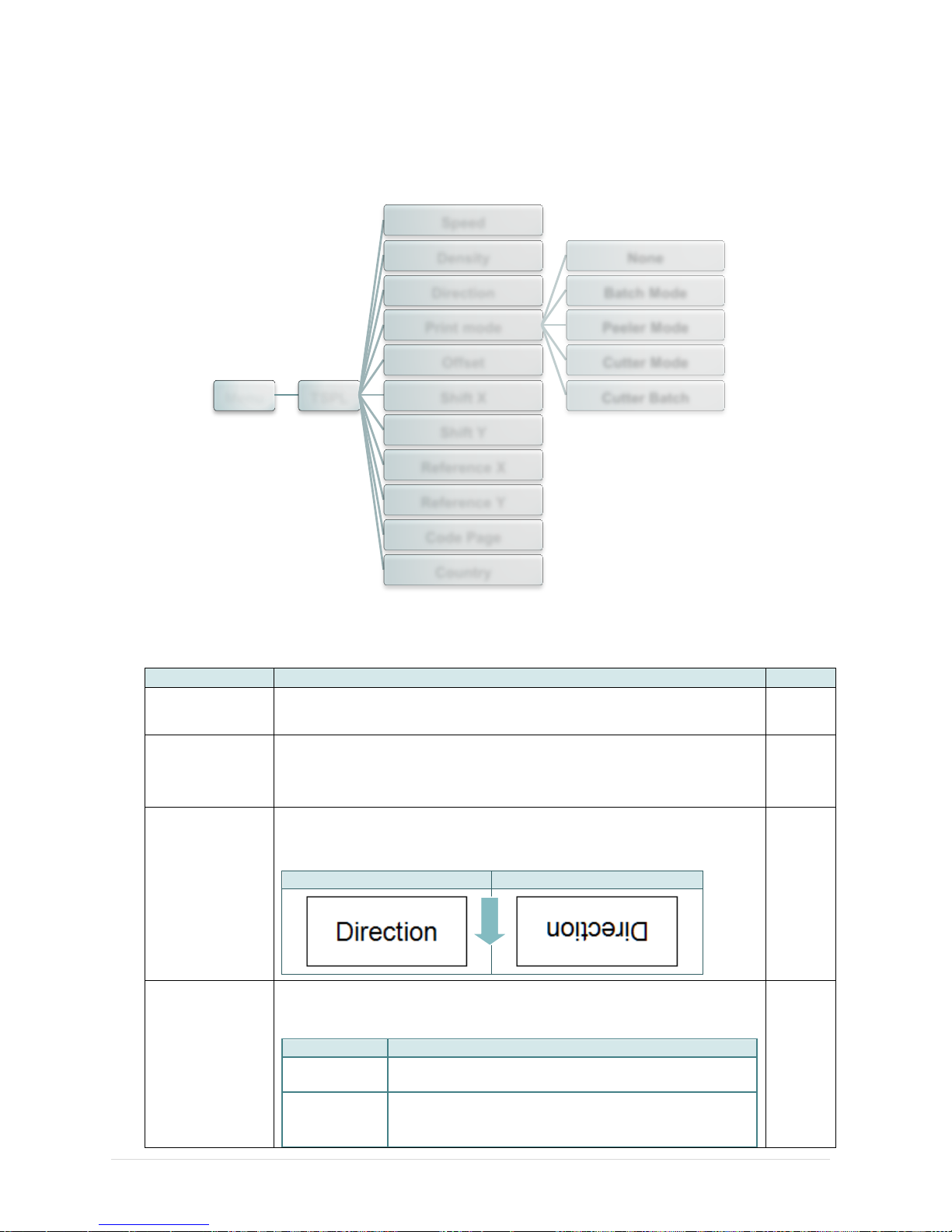
5.3 TSPL2
This “TSPL2” category can set up the printer settings for TSPL2.
Item
Description
Default
Speed
Use this item to setup print speed. The each increase or decrease
is 1 ips. Available setting is from 4 to 12.
6
Density
Use this option to setup printing darkness. The available setting is
from 0 to 15, and the step is 1. You may need to adjust your
density based on selected media.
8
Direction
The direction setting value is either 1 or 0. Use this item to setup
the printout direction.
DIRECTION 0
DIRECTION 1
0
Print mode
This item is used to set the print mode. There are 5 modes as
below,
Printer Mode
Description
None
Next label top of form is aligned to the print head burn
line location. (Tear Off Mode)
Batch Mode
Once image is printed completely, label gap/black
mark will be fed to the tear plate location for tear
away.
Batch
Mode
Menu TSPL
Speed
Density
Direction
Print mode
None
Batch Mode
Peeler Mode
Cutter Mode
Cutter Batch
Offset
Shift X
Shift Y
Reference X
Reference Y
Code Page
Country
FEED
Page 47
- 40 -
Peeler Mode
Enable the label peel off mode.
Cutter Mode
Enable the label cutter mode.
Cutter Batch
Cut the label once at the end of the printing job.
Offset
This item is used to fine tune media stop location. Available setting
value is from “+” to “-” or “0” to “9”.
+000
Shift X
This item is used to fine tune print position. Available setting value is
from “+” to “-” or “0” to “9”.
+000
Shift Y
+000
Reference X
This item is used to set the origin of printer coordinate system
horizontally and vertically. Available setting value is from “0” to “9”.
000
Reference Y
000
Code page
Use this item to set the code page of international character set.
850
Country
Use this option to set the country code.
001
Note: If printing from enclosed software/driver, the software/driver will send out the
commands, which will overwrite the settings set from the panel.
Page 48
- 41 -
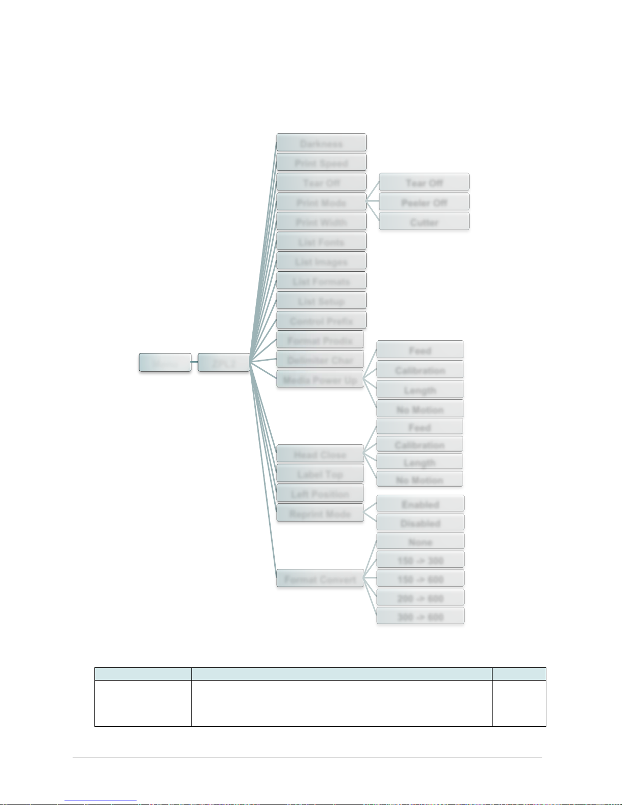
5.4 ZPL2
This “ZPL2” category can set up the printer settings for ZPL2.
Item
Description
Default
Darkness
Use this item to setup printing darkness. The available setting
is from 0 to 30, and the step is 1. You may need to adjust your
density based on selected media.
16
Menu ZPL2
Darkness
Print Speed
Tear Off
Print Mode
Tear Off
Peeler Off
Cutter Print Width
List Fonts
List Images
List Formats
List Setup
Control Prefix
Format Prodix
Delimiter Char
Media Power Up
Feed
Calibration
Length
No Motion
Head Close
Feed
Calibration
Length
No Motion
Label Top
Left Position
Reprint Mode
Enabled
Disabled
Format Convert
None
150 -> 300
150 -> 600
200 -> 600
300 -> 600
Page 49
- 42 -
Print Speed
Use this item to setup print speed. The each increase or
decrease is 1 ips. Available setting is from 1 to 6.
N/A
Tear Off
This item is used to fine tune media stop location. Available
setting value is from “+” to “-” or “0” to “9”.
+000
Print mode
This item is used to set the print mode. There are 3 modes as
below,
Printer Mode
Description
Tear Off
Next label top of form is aligned to the print
head burn line location.
Peeler Off
Enable the label peel off mode.
Cutter
Enable the label cutter mode
Tear Off
Print Width
This item is used to set print width. The available value is from
“0” to “9”.
812
List Fonts
This feature is used to print current printer available fonts list
to the label. The fonts stored in the printer’s DRAM, Flash or
optional memory card.
N/A
List Images
This feature is used to print current printer available images
list to the label. The images stored in the printer’s DRAM,
Flash or optional memory card.
N/A
List Formats
This feature is used to print current printer available formats
list to the label. The formats stored in the printer’s DRAM,
Flash or optional memory card.
N/A
List Setup
This feature is used to print current printer configuration to the
label.
N/A
Control Prefix
This feature is used to set control prefix character.
N/A
Format Prefix
This feature is used to set format prefix character.
N/A
Delimiter Char
This feature is used to set delimiter character.
N/A
Media Power Up
This option is used to set the action of the media when you
turn on the printer.
Selections
Description
Feed
Printer will advance one label
Calibration
Printer will calibration the sensor levels,
determine length and feed label
Length
Printer determine length and feed label
No Motion
Printer will not move media
No
Motion
Head Close
This option is used to set the action of the media when you
close the print head.
Selections
Description
Feed
Printer will advance one label
Calibration
Printer will calibration the sensor levels,
determine length and feed label
Length
Printer determine length and feed label
No Motion
Printer will not move media
No
Motion
Label Top
This option is used to adjust print position vertically on the
label. The range is -120 to +120 dots.
0
Left Position
This option is used to adjust print position horizontally on the
label. The range is -9999 to +9999 dots.
+0000
Page 50

- 43 -
Reprint Mode
When reprint mode is enabled, you can reprint the last label
printer by pressing button on printer’s control panel.
Disabled
Format Convert
Selects the bitmap scaling factor. The first number is the
original dots per inch (dpi) value; the second, the dpi to which
you would like to scale.
None
Note: If printing from enclosed software/driver, the software/driver will send out the
commands, which will overwrite the settings set from the panel.
Page 51
- 44 -
5.5 Sensor
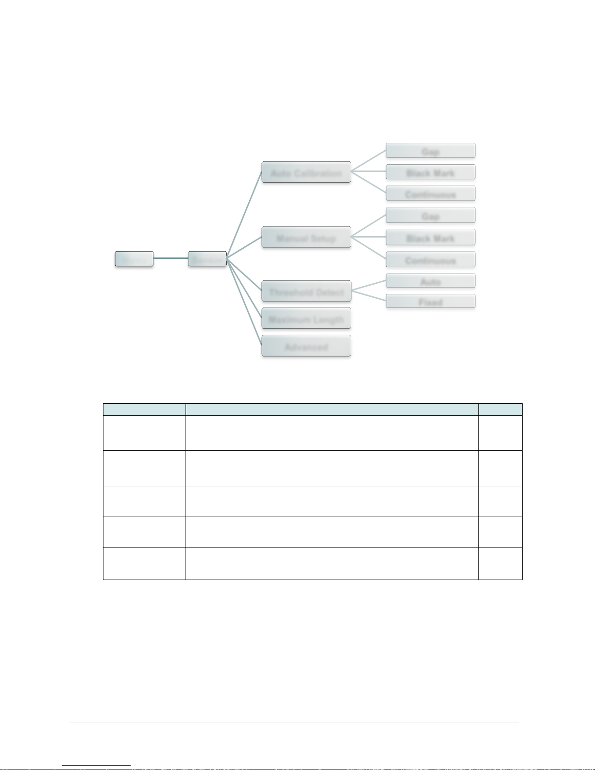
This option is used to calibrate the selected sensor. We recommend calibrate the sensor
before printing when changing the media.
Item
Description
Default
Auto
Calibration
This option is used to set the media sensor type and calibrate
the selected sensor automatically. Printer will feed 2 to 3 gap
labels to calibrate the sensor sensitivity automatically.
N/A
Manual setup
In case “Automatic” cannot apply to the media, please use
“Manual” function to set the paper length and gap/bline size
then scan the backing/mark to calibrate the sensor sensitivity.
N/A
Threshold
Detect
This option is used to set sensor sensitivity in fixed or auto.
Auto
Maximum
Length
This option is used to set the maximum length for label
calibration.
253
mm
Advanced
This function can set the minimum paper length and maximum
gap/bline length for auto-calibrate the sensor sensitivity.
N/A
Menu Sensor
Auto Calibration
Gap
Black Mark
Continuous
Manual Setup
Gap
Black Mark
Continuous
Threshold Detect
Auto
Fixed
Maximum Length
Advanced
Page 52
- 45 -
5.6 Interface
This option is used to set the printer interface settings.
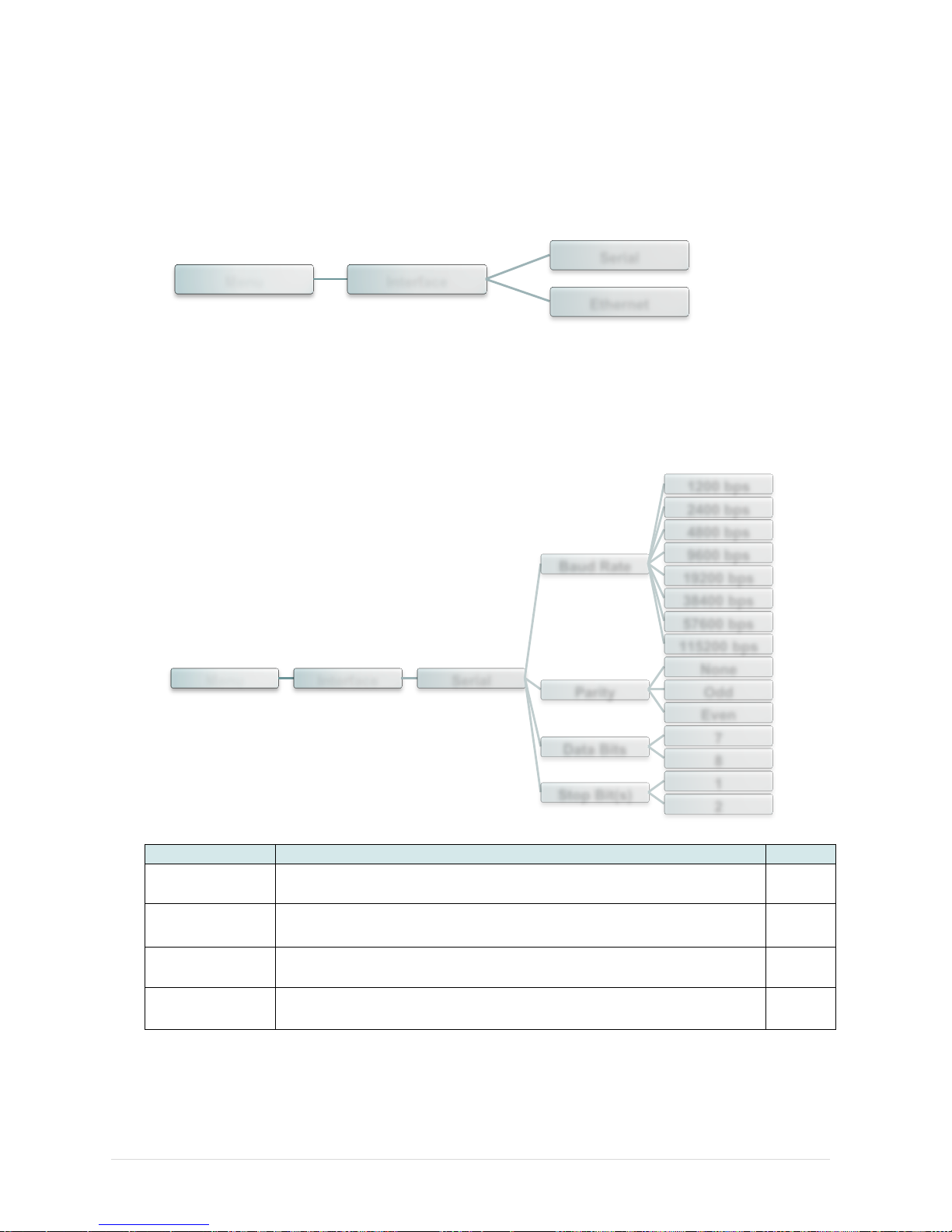
5.6.1 Serial Comm.
This option is used to set the printer RS-232 settings.
Item
Description
Default
Baud Rate
This item is used to set the RS-232 baud rate.
9600
Parity
This item is used to set the RS-232 parity.
None
Data Bits
This item is used to set the RS-232 Data Bits.
8
Stop Bit(s)
This item is used to set the RS-232 Stop Bits.
1
Menu Interface
Serial
Ethernet
Menu Interface Serial
Baud Rate
1200 bps
2400 bps
4800 bps
9600 bps
19200 bps
38400 bps
57600 bps
115200 bps
Parity
None
Odd
Even
Data Bits
7
8
Stop Bit(s)
1
2
Page 53
- 46 -
5.6.2 Ethernet
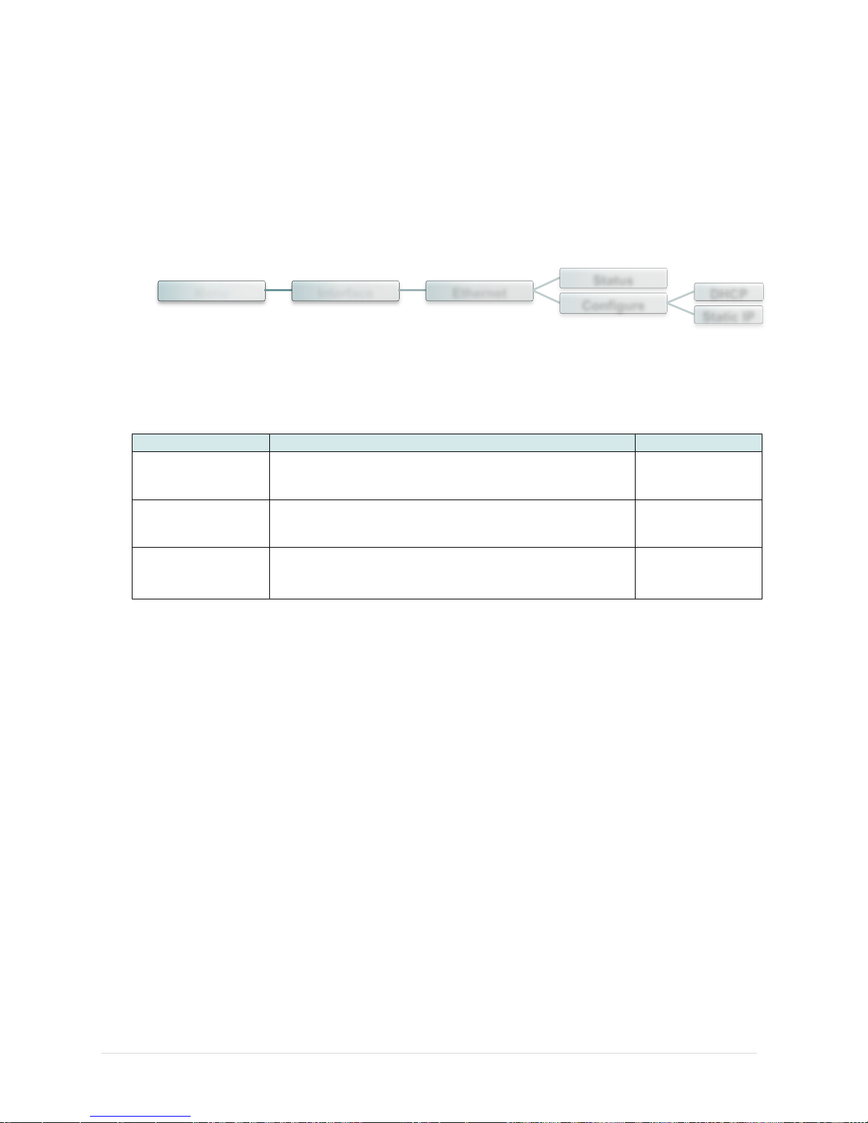
Use this menu to configure internal Ethernet configuration check the printer’s Ethernet
module status, and reset the Ethernet module.
Item
Description
Default
Status
Use this menu to check the Ethernet IP address and
MAC setting status.
N/A
DHCP
This item is used to ON or OFF the DHCP (Dynamic
Host Configuration Protocol) network protocol.
N/A
Static IP
Use this menu to set the printer’s IP address, subnet
mask and gateway.
N/A
Menu Interface Ethernet
Status
Configure
DHCP
Static IP
Page 54
- 47 -
5.7 File Manager
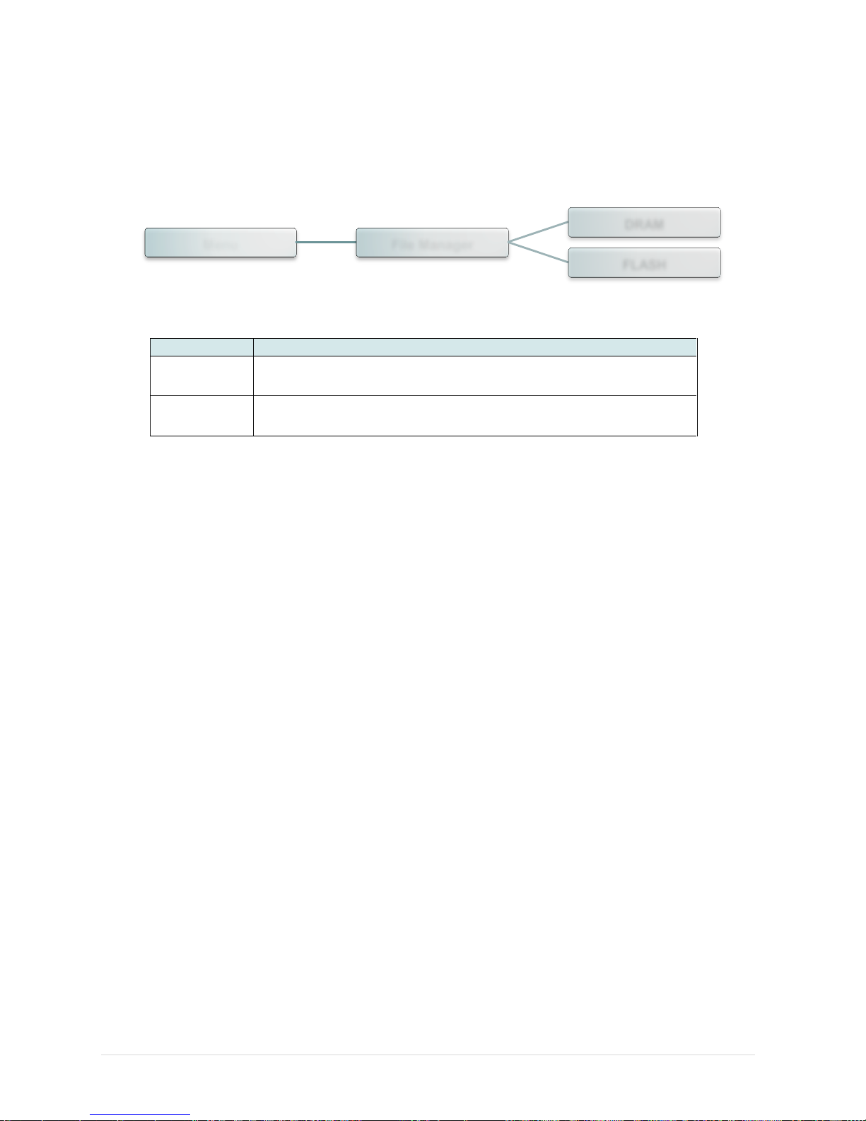
This feature is used to check the printer available memory and file list.
Item
Description
DRAM
Use this menu to show, delete and run (.BAS) the files saved in
the printer DRAM memory.
FLASH
Use this menu to show, delete and run (.BAS) the files saved in
the printer Flash memory.
Menu File Manager
DRAM
FLASH
Page 55
- 48 -
5.8 Diagnostics
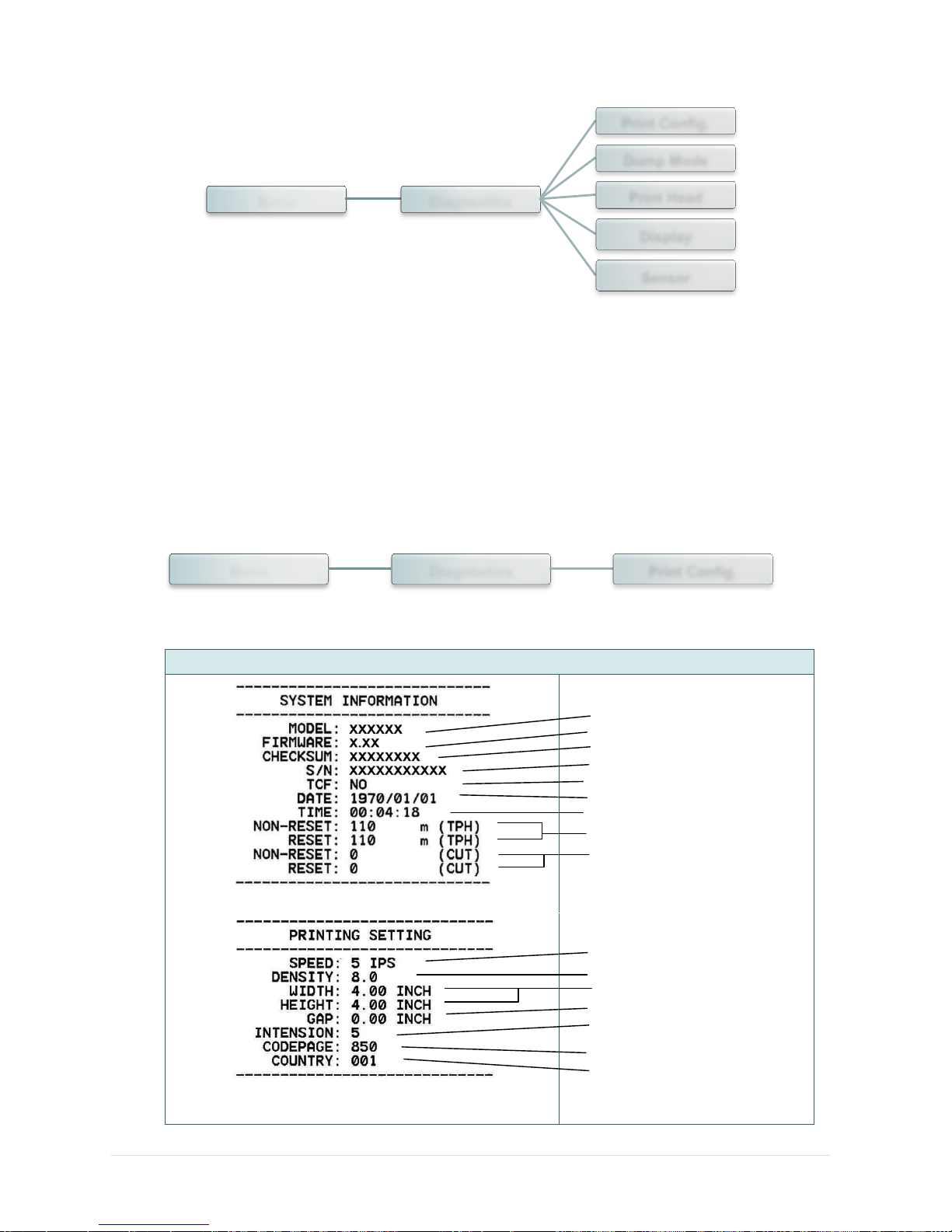
5.8.1 Print Config.
This feature is used to print current printer configuration to the label. On the configuration
printout, there is a print head test pattern, which is useful for checking if there is any dot
damage on the print head heater element.
Self-test printout
Model name
F/W version
Firmware checksum
Printer S/N
TSC configuration file
System date
System time
Printed mileage (meter)
Cutting counter
Print speed (inch/sec)
Print darkness
Label size (inch)
Gap distance (inch)
Gap/black mark sensor
intension
Code page
Country code
Menu Diagnostics
Print Config.
Dump Mode
Print Head
Display
Sensor
Menu Diagnostics Print Config.
Page 56
- 49 -
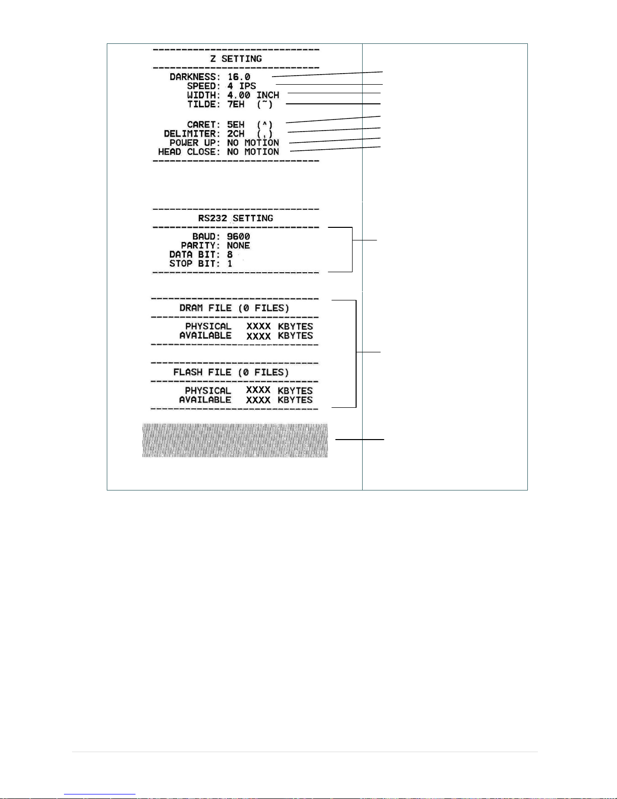
ZPL setting information
Print darkness
Print speed (inch/sec)
Label size
Control prefix
Format prefix
Delimiter prefix
Printer power up motion
Printer head close motion
Note:
ZPL is emulating for Zebra®
language.
RS232 serial port configuration
Numbers of download files
Total & available memory
space
Print head check pattern
Note:
Checking dot damage requires 4” wide paper width.
Page 57
- 50 -
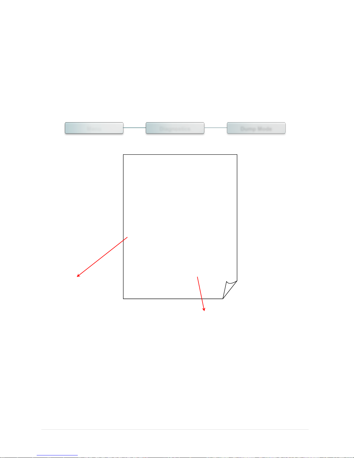
5.8.2 Dump Mode
Captures the data from the communications port and prints out the data received by printer.
In the dump mode, all characters will be printed in 2 columns. The left side characters are
received from your system and right side data are the corresponding hexadecimal value of
the characters. It allows users or engineers to verify and debug the program.
DOWNLOA 0D 0A 44 4F 57 4E 4C 4F 4I
D „TEST2. 44 20 22 54 45 53 54 32 2E
DAT“,5,CL 44 41 54 22 2C 35 2C 43 4C
S DOWNLO 53 0D 0A 44 4F 57 4E 4C 4F
AD F,“TES 41 44 20 46 2C 22 54 45 53
T4.DAT“,5 54 34 2E 44 41 54 22 2C 35
,CLS DOW 2C 43 4C 53 0D 0A 44 4F 57
NLOAD „TE 4E 4C 4F 41 44 20 22 54 45
ST2.DAT”, 53 54 32 2E 44 41 54 22 2C
5,CLS DO 35 2C 43 4C 53 0D 0A 44 4F
WNLOAD F, 57 4E 4C 4F 41 44 20 46 2C
„TEST4.DA 22 54 45 53 54 34 2E 44 41
T”,5,CLS 54 22 2C 35 2C 43 4C 53 0D
DOWNLOAD 0A 44 4F 57 4E 4C 4F 41 44
“TEST2.D 20 22 54 45 53 54 32 2E 44
AT”,5,CLS 41 54 22 2C 35 2C 43 4C 53
DOWNLOA 0D 0A 44 4F 57 4E 4C 4F 4I
D F,“TEST 44 20 46 2C 22 54 45 53 54
4.DAT“,5, 34 2E 44 41 54 22 2C 35 2C
CLS 43 4C 53 0D 0A
ASCII Data
Hexdecimal data related to left column of ASCII data
Note:
Dump mode requires 4” wide paper width.
Menu Diagnostics Dump Mode
Page 58
- 51 -
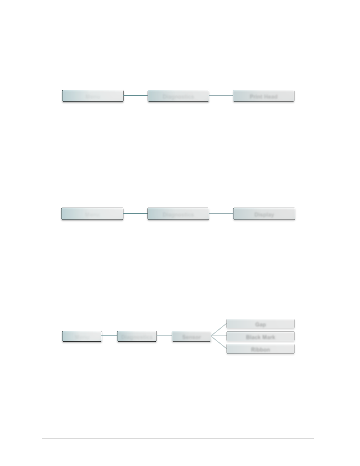
5.8.3 Print Head
This feature can check the temperature, resistance and bad dots for print head.
5.8.4 Display
This feature can check the display for printer.
5.8.5 Sensor
This feature can check the intension & reading values for printer sensors.
Menu Diagnostics Print Head
Menu Diagnostics Display
Menu Diagnostics Sensor
Gap
Black Mark
Ribbon
Page 59
- 52 -
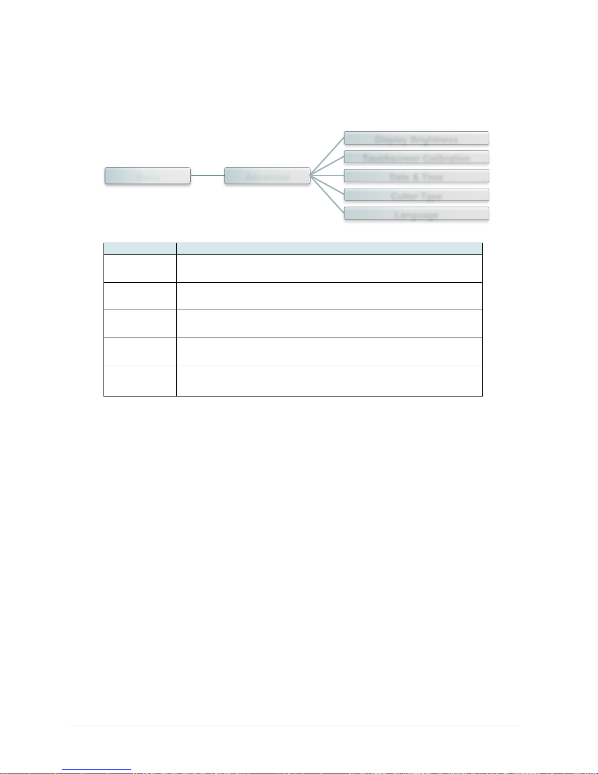
5.9 Advanced
This feature is used to set the printer advanced settings.
Item
Description
Display
Brightness
This item is used to setup the brightness for display.
Touchscreen
Calibration
This item is used to calibrate the center of the cross for best result
for touchscreen.
Date & Time
This item is used to setup the date and time on display.
Cutter Type
This item is used to set the cutter type.
Language
This item is used to setup the language on display.
Menu Advanced
Display Brightness
Touchscreen Calibration
Date & Time
Cutter Type
Language
Page 60
- 53 -
5.10 Service
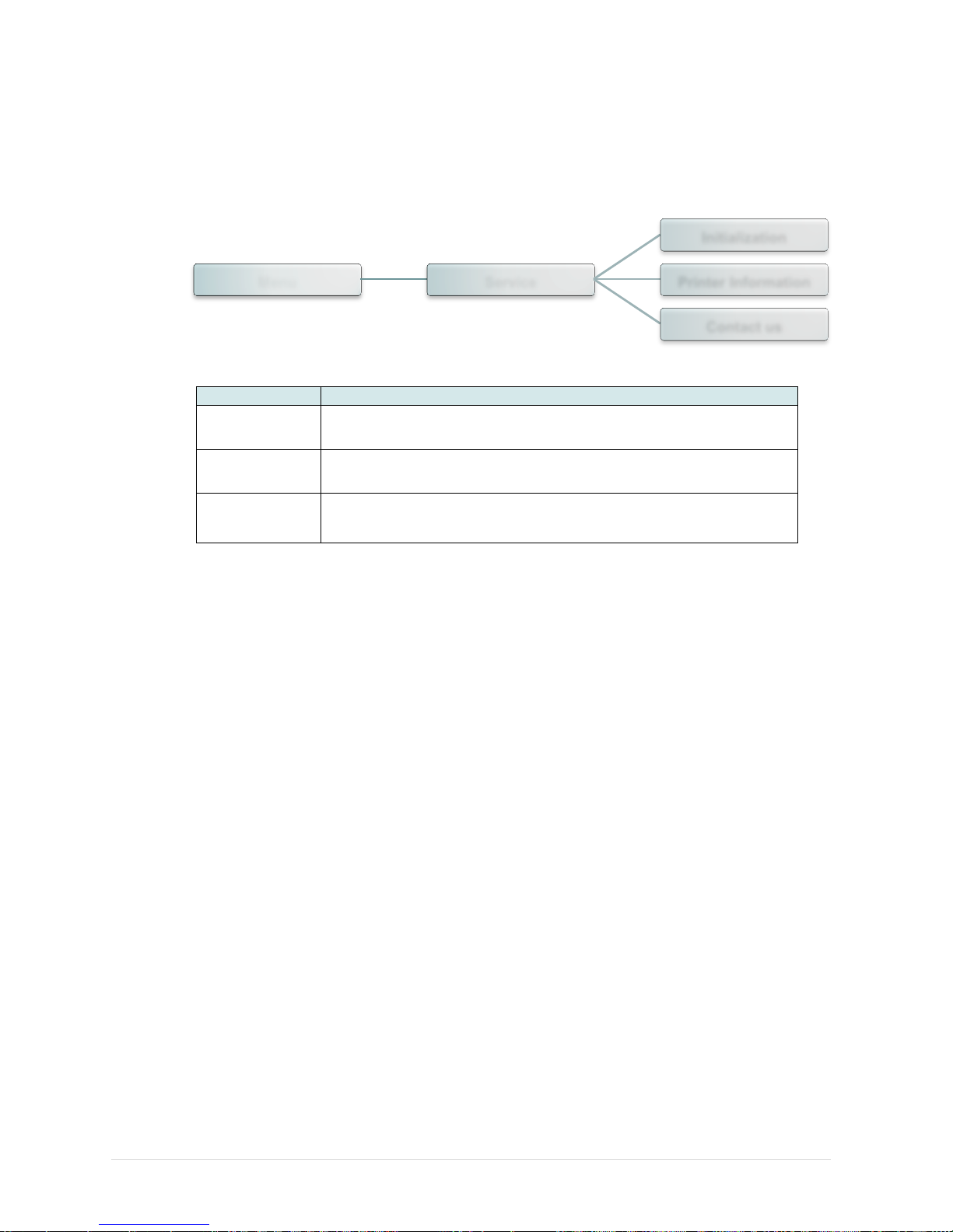
This feature is used to restore printer settings to defaults and checking information for printer.
Item
Description
Initialization
This feature is used to restore printer settings to defaults.
Printer
Information
This feature is used to check printer serial number, printed mileage(m),
labels(pcs.) and cutting counter.
Contact us
This feature is used to check the contact information for tech support
service
Menu Service
Initialization
Printer Information
Contact us
Page 61
- 54 -
6. LCD Menu Function for MU Series
6.1 Enter the Main Menu
Press the button to enter the main menu or to cancel the setting and return to the
previous menu. Press button to scroll up the menu list. Press button to scroll down
the menu list. Press button to set the values into printer.
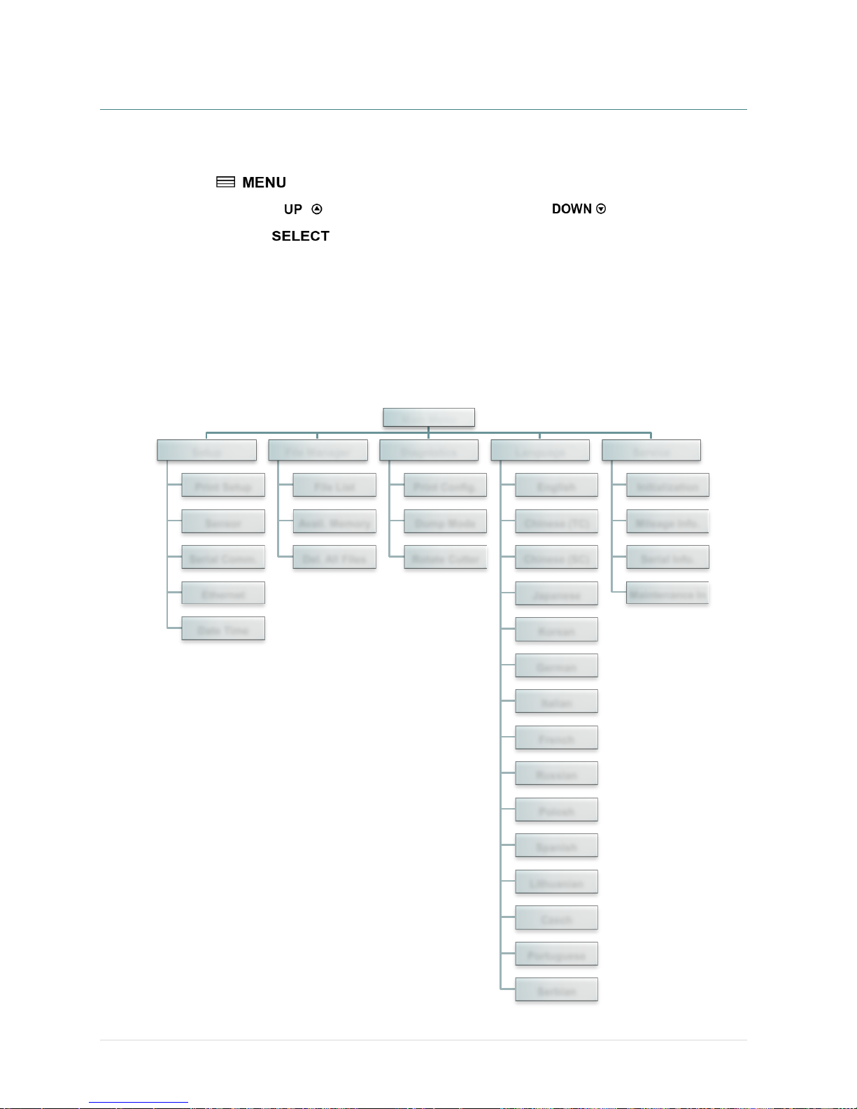
6.2 Main Menu Overview
There are 5 categories for the main menu. You can easy to set the settings of printer without
connecting the computer. Please refer to following sections for more details.
Main Menu
Setup
Print Setup
Sensor
Serial Comm.
Ethernet
Date Time
File Manager
File List
Avail. Memory
Del. All Files
Diagnistics
Print Config.
Dump Mode
Rotate Cutter
Language
English
Chinese (TC)
Chinese (SC)
Japanese
Korean
German
Italian
French
Russian
Polosh
Spanish
Lithuanian
Czech
Portuguese
Serbian
Service
Initialization
Mileage Info.
Serial Info.
Maintenance In
Page 62
- 55 -
6.3 Setup
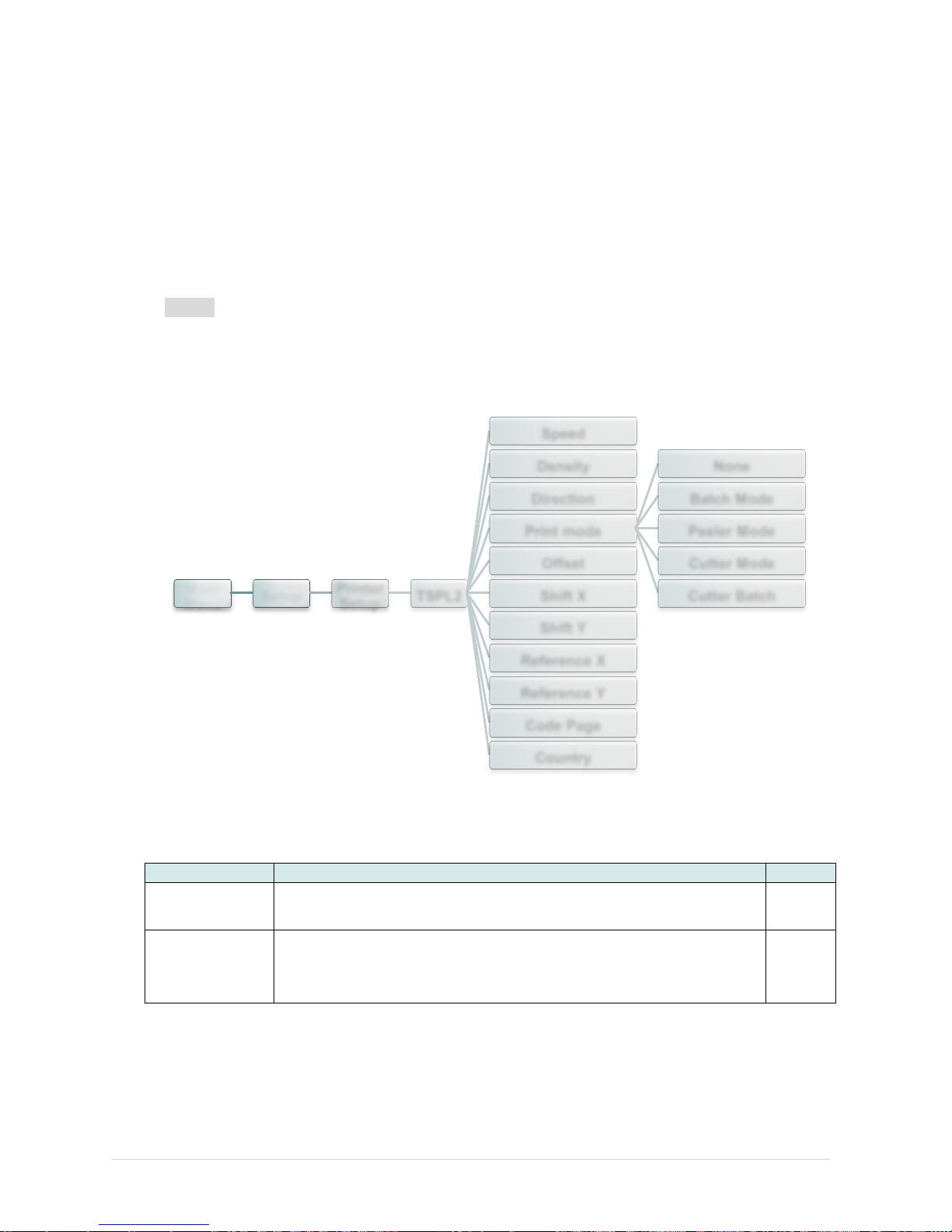
This “Setup” category can set up the printer settings for TSPL2, ZPL2, sensor, serial
interface, and Ethernet interface.
6.3.1 Printer Setup (TSPL2/ ZPL2)
TSPL2
This “TSPL” category can set up the printer settings for TSPL2.
Item
Description
Default
Speed
Use this item to setup print speed. The each increase or decrease
is 1 ips. Available setting is from 4 to 12.
6
Density
Use this option to setup printing darkness. The available setting is
from 0 to 15, and the step is 1. You may need to adjust your
density based on selected media.
8
Main
Menu
Setup
Printer
Setup
TSPL2
Speed
Density
Direction
Print mode
None
Batch Mode
Peeler Mode
Cutter Mode
Cutter Batch
Offset
Shift X
Shift Y
Reference X
Reference Y
Code Page
Country
Page 63
- 56 -
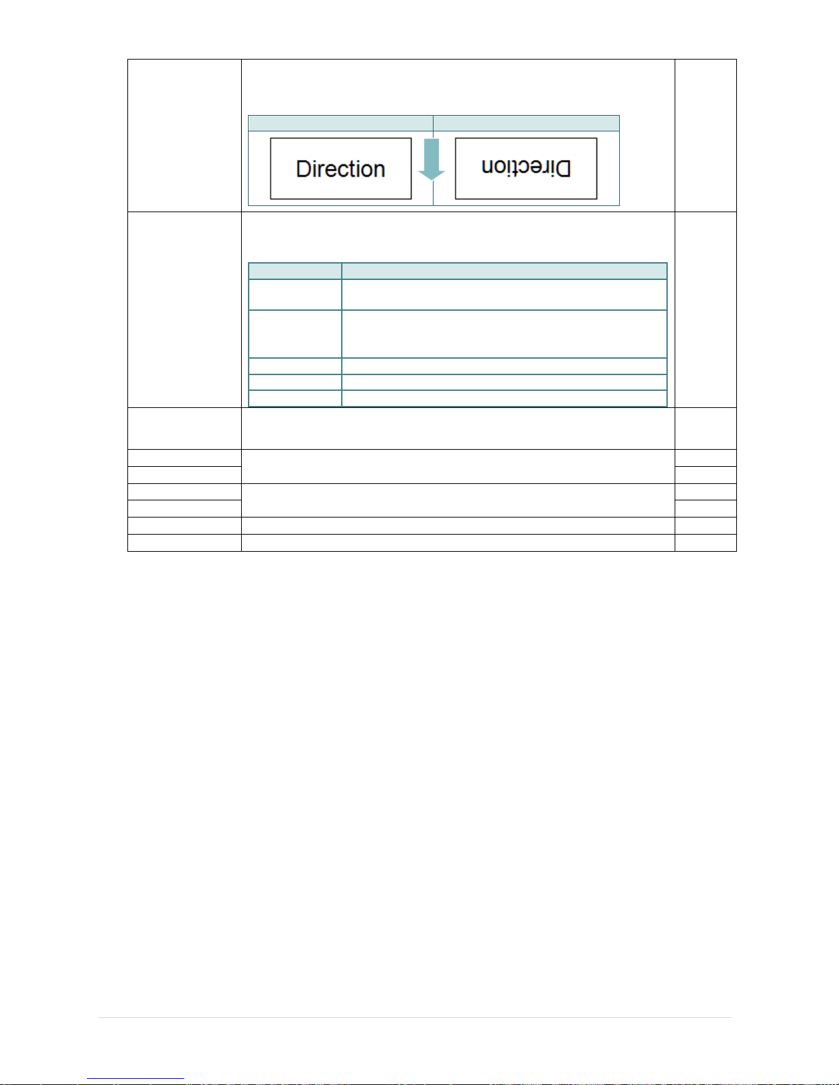
Direction
The direction setting value is either 1 or 0. Use this item to setup
the printout direction.
DIRECTION 0
DIRECTION 1
0
Print mode
This item is used to set the print mode. There are 5 modes as
below,
Printer Mode
Description
None
Next label top of form is aligned to the print head burn
line location. (Tear Off Mode)
Batch Mode
Once image is printed completely, label gap/black
mark will be fed to the tear plate location for tear
away.
Peeler Mode
Enable the label peel off mode.
Cutter Mode
Enable the label cutter mode.
Cutter Batch
Cut the label once at the end of the printing job.
Batch
Mode
Offset
This item is used to fine tune media stop location. Available setting
value is from “+” to “-” or “0” to “9”.
+000
Shift X
This item is used to fine tune print position. Available setting value is
from “+” to “-” or “0” to “9”.
+000
Shift Y
+000
Reference X
This item is used to set the origin of printer coordinate system
horizontally and vertically. Available setting value is from “0” to “9”.
000
Reference Y
000
Code page
Use this item to set the code page of international character set.
850
Country
Use this option to set the country code.
001
Note: If printing from enclosed software/driver, the software/driver will send out the
commands, which will overwrite the settings set from the panel.
FEED
Page 64
- 57 -
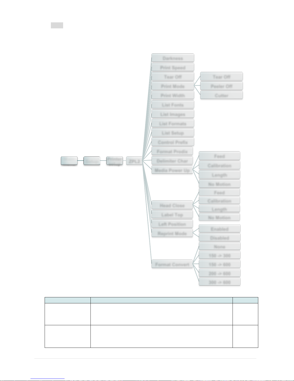
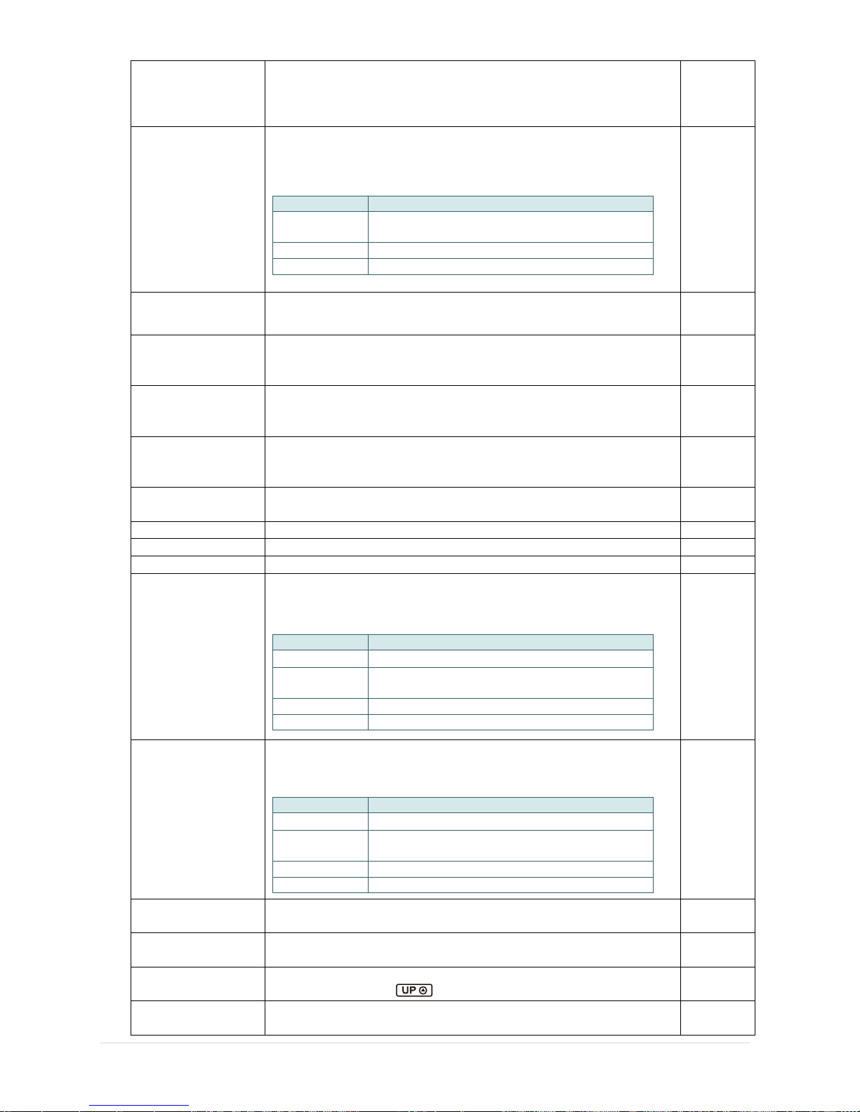
ZPL2
This “ZPL2” category can set up the printer settings for ZPL2.
Item
Description
Default
Darkness
Use this item to setup printing darkness. The available setting
is from 0 to 30, and the step is 1. You may need to adjust your
density based on selected media.
16
Print Speed
Use this item to setup print speed. The each increase or
decrease is 1 ips. Available setting is from 1 to 6.
2
Main
menu
Setup
Printer
setup
ZPL2
Darkness
Print Speed
Tear Off
Print Mode
Tear Off
Peeler Off
Cutter Print Width
List Fonts
List Images
List Formats
List Setup
Control Prefix
Format Prodix
Delimiter Char
Media Power Up
Feed
Calibration
Length
No Motion
Head Close
Feed
Calibration
Length
No Motion
Label Top
Left Position
Reprint Mode
Enabled
Disabled
Format Convert
None
150 -> 300
150 -> 600
200 -> 600
300 -> 600
Page 65
- 58 -
Tear Off
This item is used to fine tune media stop location. Available
setting value is from “+” to “-” or “0” to “9”.
+000
Print mode
This item is used to set the print mode. There are 3 modes as
below,
Printer Mode
Description
Tear Off
Next label top of form is aligned to the print
head burn line location.
Peeler Off
Enable the label peel off mode.
Cutter
Enable the label cutter mode
Tear Off
Print Width
This item is used to set print width. The available value is from
“0” to “9”.
812
List Fonts
This feature is used to print current printer available fonts list
to the label. The fonts stored in the printer’s DRAM, Flash or
optional memory card.
N/A
List Images
This feature is used to print current printer available images
list to the label. The images stored in the printer’s DRAM,
Flash or optional memory card.
N/A
List Formats
This feature is used to print current printer available formats
list to the label. The formats stored in the printer’s DRAM,
Flash or optional memory card.
N/A
List Setup
This feature is used to print current printer configuration to the
label.
N/A
Control Prefix
This feature is used to set control prefix character.
N/A
Format Prefix
This feature is used to set format prefix character.
N/A
Delimiter Char
This feature is used to set delimiter character.
N/A
Media Power Up
This option is used to set the action of the media when you
turn on the printer.
Selections
Description
Feed
Printer will advance one label
Calibration
Printer will calibration the sensor levels,
determine length and feed label
Length
Printer determine length and feed label
No Motion
Printer will not move media
No
Motion
Head Close
This option is used to set the action of the media when you
close the print head.
Selections
Description
Feed
Printer will advance one label
Calibration
Printer will calibration the sensor levels,
determine length and feed label
Length
Printer determine length and feed label
No Motion
Printer will not move media
No
Motion
Label Top
This option is used to adjust print position vertically on the
label. The range is -120 to +120 dots.
0
Left Position
This option is used to adjust print position horizontally on the
label. The range is -9999 to +9999 dots.
+0000
Reprint Mode
When reprint mode is enabled, you can reprint the last label
printer by pressing button on printer’s control panel.
Disabled
Format Convert
Selects the bitmap scaling factor. The first number is the
original dots per inch (dpi) value; the second, the dpi to which
None
Page 66

- 59 -
you would like to scale.
Note: If printing from enclosed software/driver, the software/driver will send out the
commands, which will overwrite the settings set from the panel.
Page 67
- 60 -
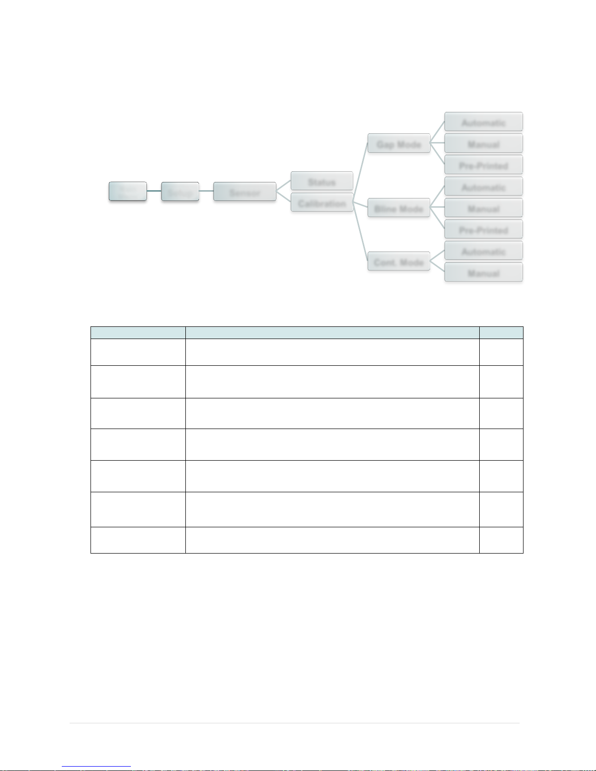
6.3.2 Sensor
This option is used to calibrate the selected sensor. We recommend calibrate the sensor
before printing when changing the media.
Item
Description
Default
Status
This function is available to check the printer’s sensor status.
N/A
Gap Mode
This item is used to set the gap media sensor type and
calibrate the sensor.
N/A
Bline Mode
This item is used to set the black mark media sensor type and
calibrate the sensor.
N/A
Cont. Mode
This item is used to set the continuous media sensor type and
calibrate the sensor.
N/A
Automatic
Printer will feed 2 to 3 gap labels to calibrate the sensor
sensitivity automatically.
N/A
Manual
In case “Automatic” cannot apply to the media, please use
“Manual” function to set the paper length and gap/bline size
then scan the backing/mark to calibrate the sensor sensitivity.
N/A
Pre-Printed
This function can set the min. paper length and max gap/bline
length before auto-calibrate the sensor sensitivity.
N/A
Main
Menu
Setup Sensor
Status
Calibration
Gap Mode
Automatic
Manual
Pre-Printed
Bline Mode
Automatic
Manual
Pre-Printed
Cont. Mode
Automatic
Manual
Page 68
- 61 -
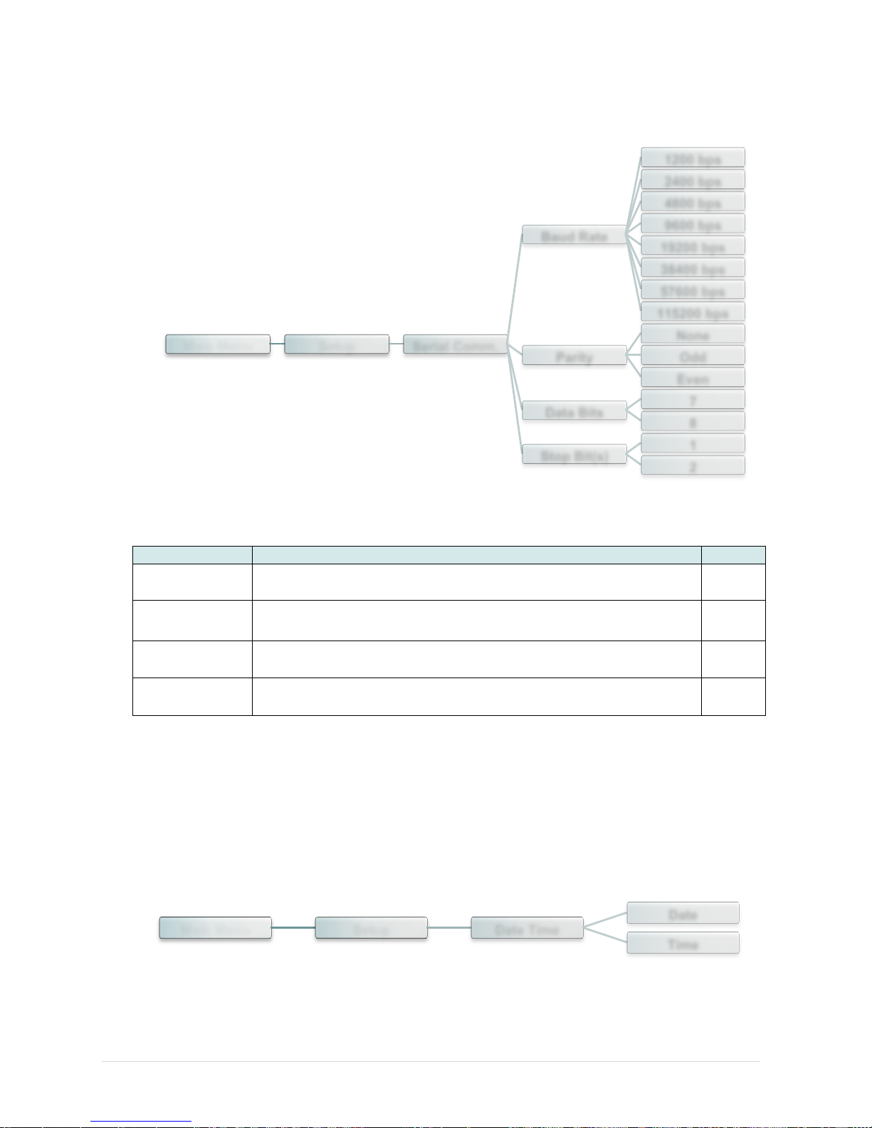
6.3.3 Serial Comm.
This option is used to set the printer RS-232 settings.
Item
Description
Default
Baud Rate
This item is used to set the RS-232 baud rate.
9600
Parity
This item is used to set the RS-232 parity.
None
Data Bits
This item is used to set the RS-232 Data Bits.
8
Stop Bit(s)
This item is used to set the RS-232 Stop Bits.
1
6.3.4 Date Time
This option is used to set the date & time for RTC.
Main Menu Setup Serial Comm.
Baud Rate
1200 bps
2400 bps
4800 bps
9600 bps
19200 bps
38400 bps
57600 bps
115200 bps
Parity
None
Odd
Even
Data Bits
7
8
Stop Bit(s)
1
2
Main Menu Setup Date Time
Date
Time
Page 69
- 62 -
6.4 File Manager
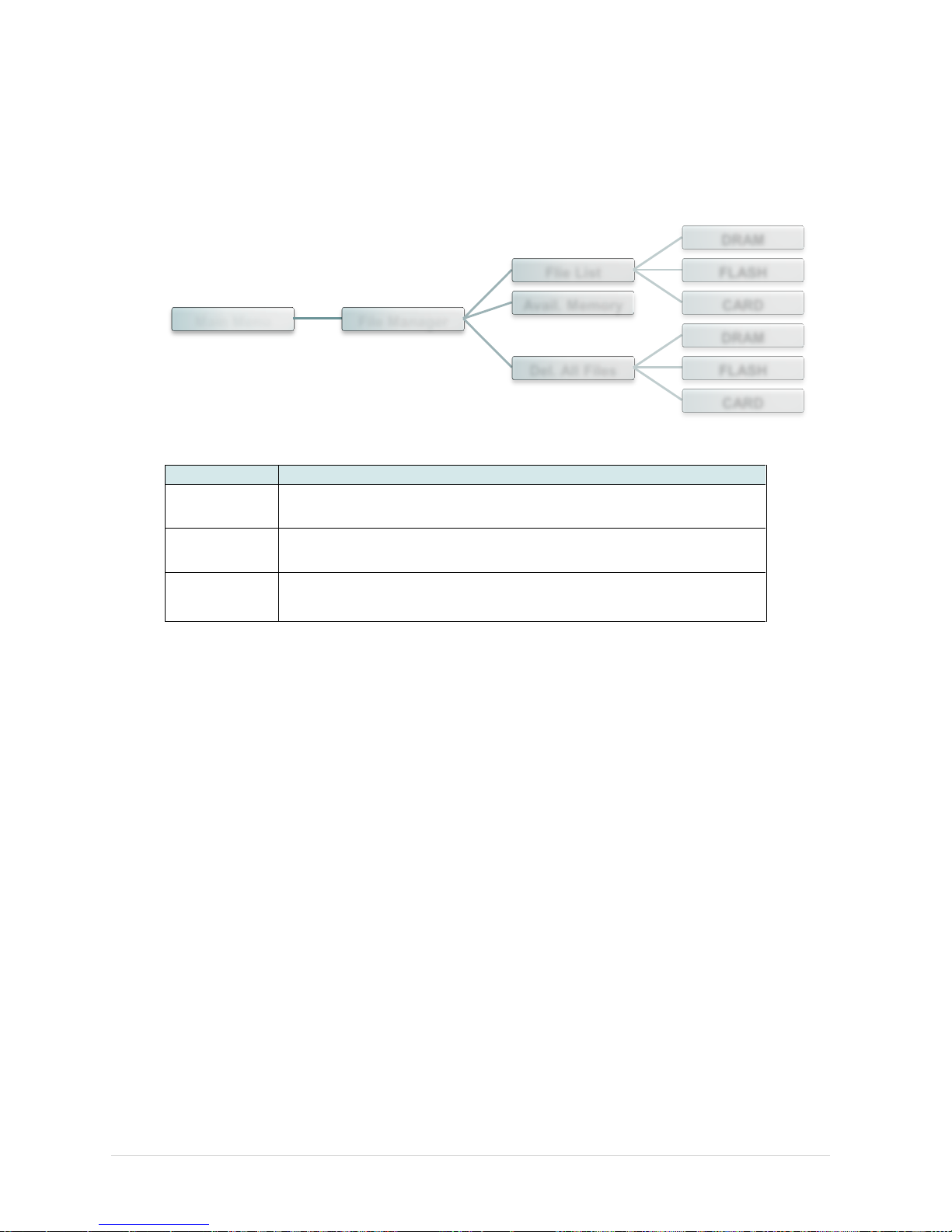
This feature is used to check the printer available memory and file list.
Item
Description
File List
Use this menu to show, delete and run (.BAS) the files saved in
the printer DRAM/Flash/Card memory.
Avail.
Memory
Use this menu to show available memory space.
Del. All Files
Use this menu to delete all files.
Main Menu File Manager
Flie List
DRAM
FLASH
CARD Avail. Memory
Del. All Files
DRAM
FLASH
CARD
Page 70
- 63 -
6.5 Diagnostics
6.5.1 Print Config.
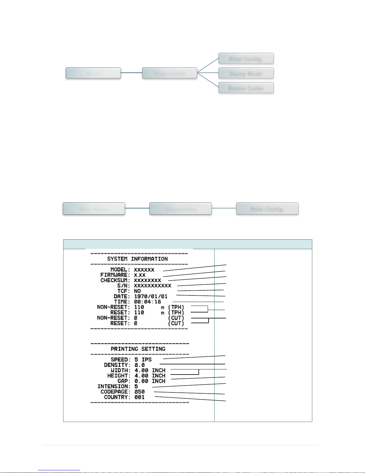
This feature is used to print current printer configuration to the label. On the configuration
printout, there is a print head test pattern, which is useful for checking if there is any dot
damage on the print head heater element.
Self-test printout
Model name
F/W version
Firmware checksum
Printer S/N
TSC configuration file
System date
System time
Printed mileage (meter)
Cutting counter
Print speed (inch/sec)
Print darkness
Label size (inch)
Gap distance (inch)
Gap/black mark sensor
intension
Code page
Country code
Menu Diagnostics
Print Config.
Dump Mode
Rotate Cutter
Main Menu Diagnostics Print Config.
Page 71
- 64 -
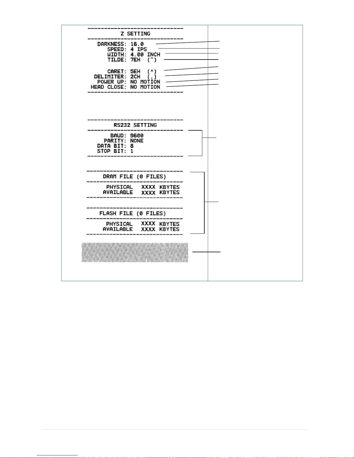
ZPL setting information
Print darkness
Print speed (inch/sec)
Label size
Control prefix
Format prefix
Delimiter prefix
Printer power up motion
Printer head close motion
Note:
ZPL is emulating for Zebra®
language.
RS232 serial port configuration
Numbers of download files
Total & available memory
space
Print head check pattern
Note:
Checking dot damage requires 4” wide paper width.
Page 72
- 65 -
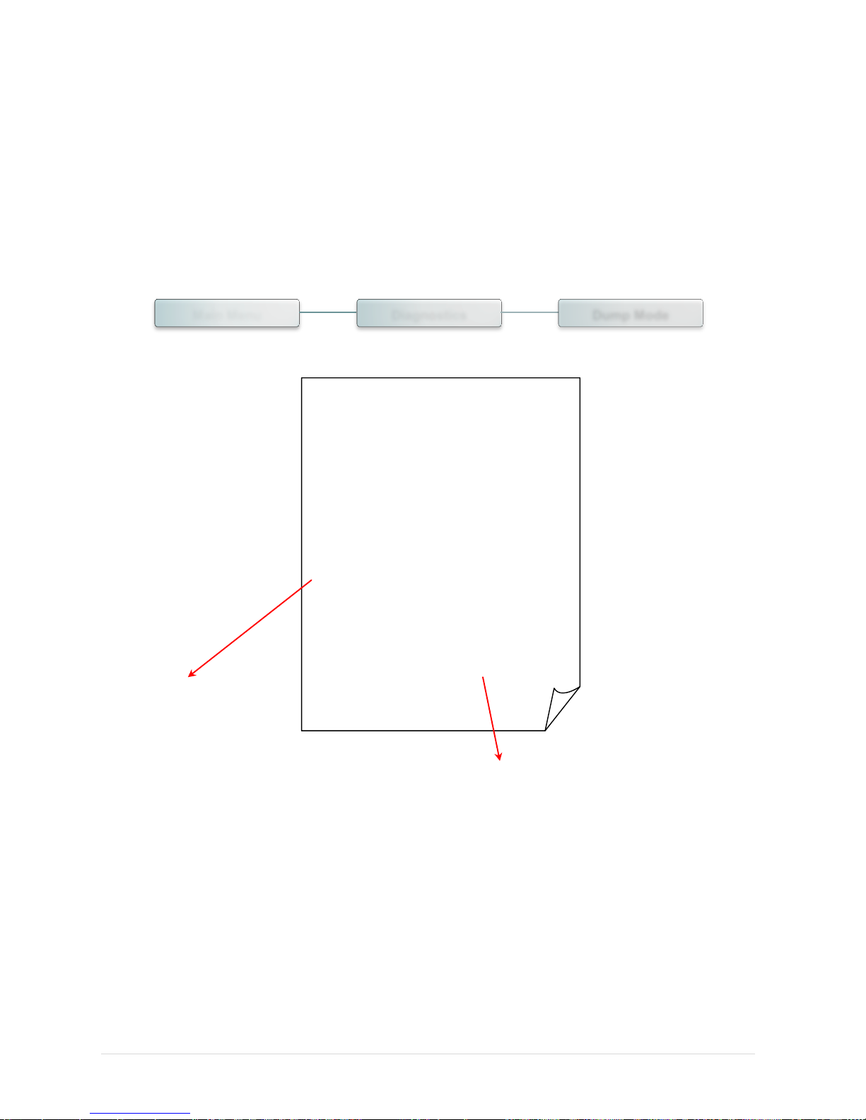
6.5.2 Dump Mode
Captures the data from the communications port and prints out the data received by printer.
In the dump mode, all characters will be printed in 2 columns. The left side characters are
received from your system and right side data are the corresponding hexadecimal value of
the characters. It allows users or engineers to verify and debug the program.
DOWNLOA 0D 0A 44 4F 57 4E 4C 4F 4I
D „TEST2. 44 20 22 54 45 53 54 32 2E
DAT“,5,CL 44 41 54 22 2C 35 2C 43 4C
S DOWNLO 53 0D 0A 44 4F 57 4E 4C 4F
AD F,“TES 41 44 20 46 2C 22 54 45 53
T4.DAT“,5 54 34 2E 44 41 54 22 2C 35
,CLS DOW 2C 43 4C 53 0D 0A 44 4F 57
NLOAD „TE 4E 4C 4F 41 44 20 22 54 45
ST2.DAT”, 53 54 32 2E 44 41 54 22 2C
5,CLS DO 35 2C 43 4C 53 0D 0A 44 4F
WNLOAD F, 57 4E 4C 4F 41 44 20 46 2C
„TEST4.DA 22 54 45 53 54 34 2E 44 41
T”,5,CLS 54 22 2C 35 2C 43 4C 53 0D
DOWNLOAD 0A 44 4F 57 4E 4C 4F 41 44
“TEST2.D 20 22 54 45 53 54 32 2E 44
AT”,5,CLS 41 54 22 2C 35 2C 43 4C 53
DOWNLOA 0D 0A 44 4F 57 4E 4C 4F 4I
D F,“TEST 44 20 46 2C 22 54 45 53 54
4.DAT“,5, 34 2E 44 41 54 22 2C 35 2C
CLS 43 4C 53 0D 0A
ASCII Data
Hexdecimal data related to left column of ASCII data
Note:
Dump mode requires 4” wide paper width.
Main Menu Diagnostics Dump Mode
Page 73
- 66 -
6.5.3 Rotate Cutter
In case paper is jammed in the cutter, this feature can rotate the cutter blade forward or reverse
direction, which is helpful to remove the jammed paper easily from the cutter.
Main Menu Diagnostics Rotate Cutter
Page 74
- 67 -
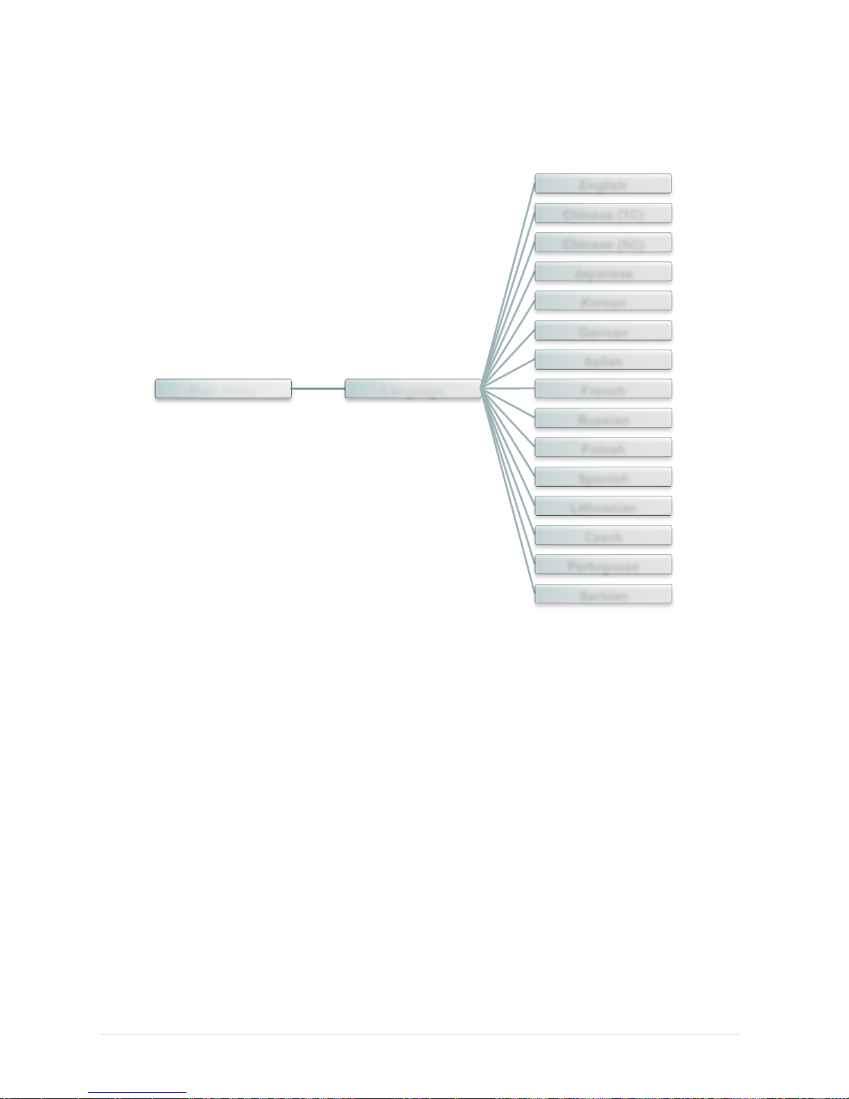
6.6 Language
This item is used to setup the language on display.
Main Menu Language
English
Chinese (TC)
Chinese (SC)
Japanese
Korean
German
Italian
French
Russian
Polosh
Spanish
Lithuanian
Czech
Portuguese
Serbian
Page 75
- 68 -
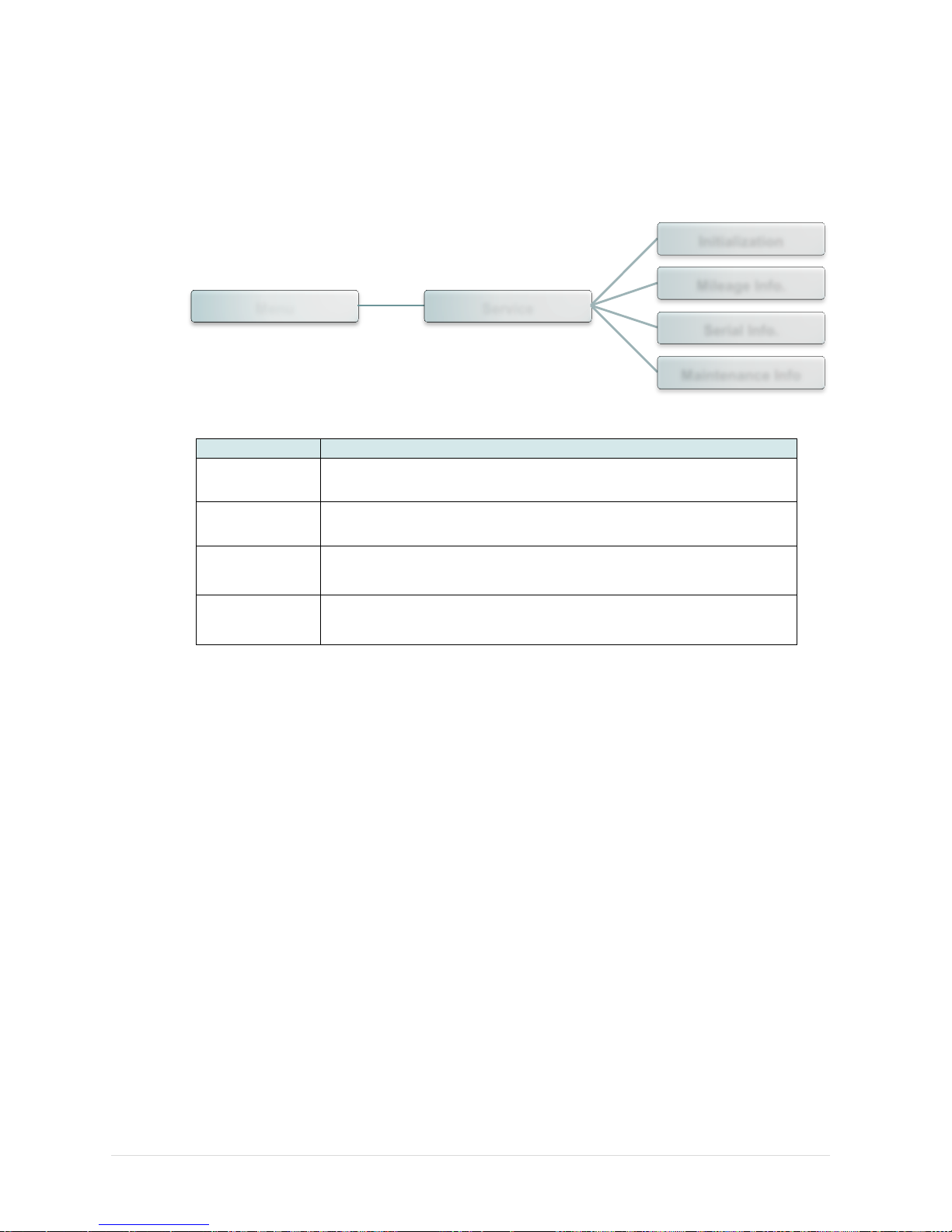
6.7 Service
This feature is used to restore printer settings to defaults and checking information for printer.
Item
Description
Initialization
This feature is used to restore printer settings to defaults.
Mileage Info.
This feature is used to check the printed mileage
Serial Info.
This feature is used to check the printer serial number
Maintenance
Info
This feature is used to check the maintenance information
Menu Service
Initialization
Mileage Info.
Serial Info.
Maintenance Info
Page 76
- 69 -
7. Diagnostic Tool
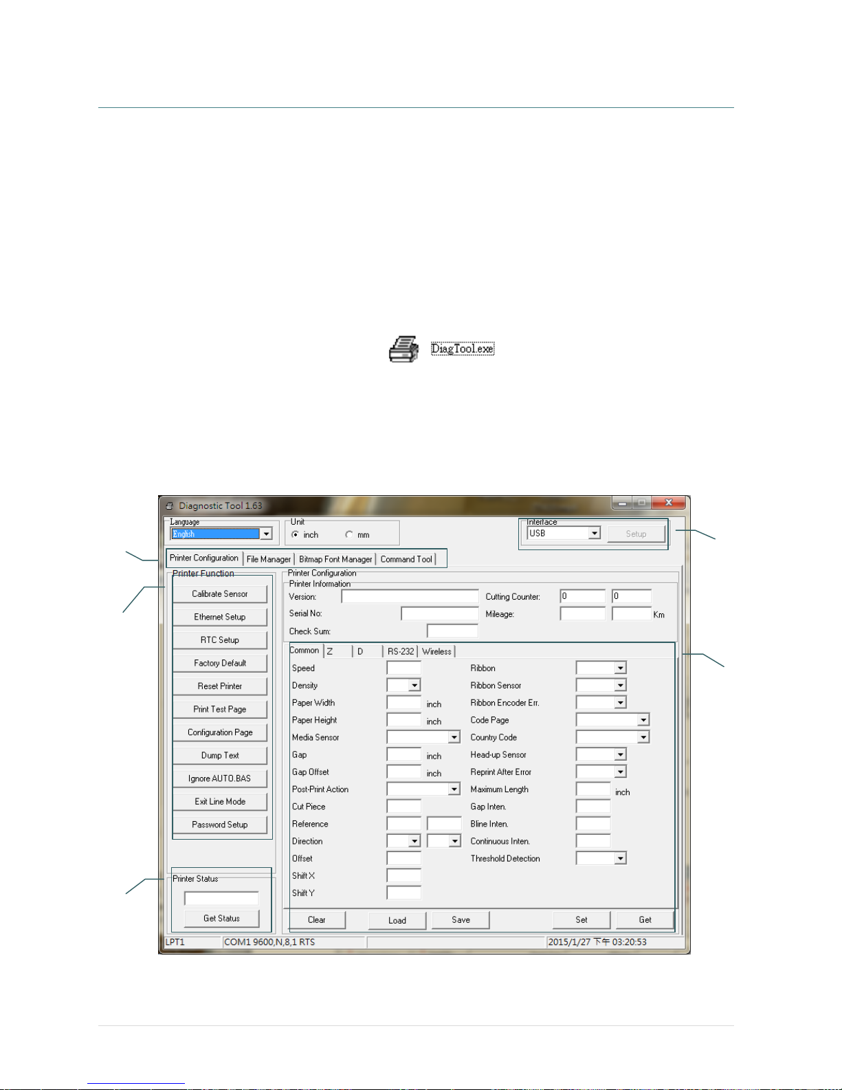
TSC’s Diagnostic Utility is an integrated tool incorporating features that enable you to explore a printer’s
settings/status; change a printer’s settings; download graphics, fonts and firmware; create a printer
bitmap font; and send additional commands to a printer. With the aid of this powerful tool, you can
review printer status and setting in an instant, which makes it much easier to troubleshoot problems and
other issues.
7.1 Start the Diagnostic Tool
1. Double click on the Diagnostic tool icon to start the software.
2. There are four features (Printer Configuration, File Manager, Bitmap Font Manager, Command Tool)
included in the Diagnostic utility.
Features tab
Printer
functions
Interface
Printer Status
Printer setup
Page 77
- 70 -
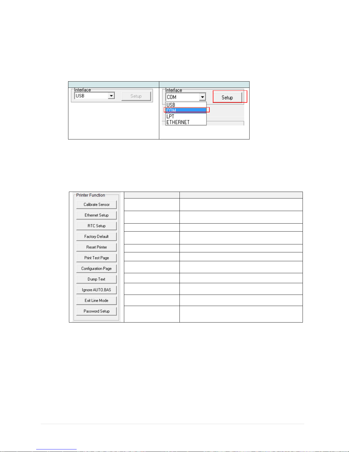
7.2 Printer Function
1. Connect the printer and computer with a cable.
2. Select the PC interface connected with bar code printer.
USB cable
Other cable
The default interface setting is USB
interface. If USB interface is
connected with printer, no other
settings need to be changed in the
interface field.
3. Click the “Printer Function” button to setup.
4. The detail functions in the Printer Function Group are listed as below.
Function
Description
Calibrate Sensor
Calibrate the sensor specified in the Printer
Setup group media sensor field
Ethernet Setup
Setup the IP address, subnet mask, gateway for
the on board Ethernet
RTC Setup
Synchronize printer Real Time Clock with PC
Factory Default
Initialize the printer and restore the settings to
factory default.
Reset Printer
Reboot printer
Print Test Page
Print a test page
Configuration Page
Print printer configuration
Dump Text
To activate the printer dump mode.
Ignore AUTO.BAS
Ignore the downloaded AUTO.BAS program
Exit Line Mode
Exit line mode.
Password Setup
Set the password to protect the settings
For more information about Diagnostic Tool, please refer to the diagnostic utility quick start
guide in the CD disk \ Utilities directory.
1
2
Page 78
- 71 -
7.3 Setting Ethernet by Diagnostic Tool
The Diagnostic Utility is enclosed in the CD disk \Utilities directory. Users can use Diagnostic Tool to
setup the Ethernet by RS-232, USB and Ethernet interfaces. The following contents will instruct users
how to configure the Ethernet by these three interfaces.
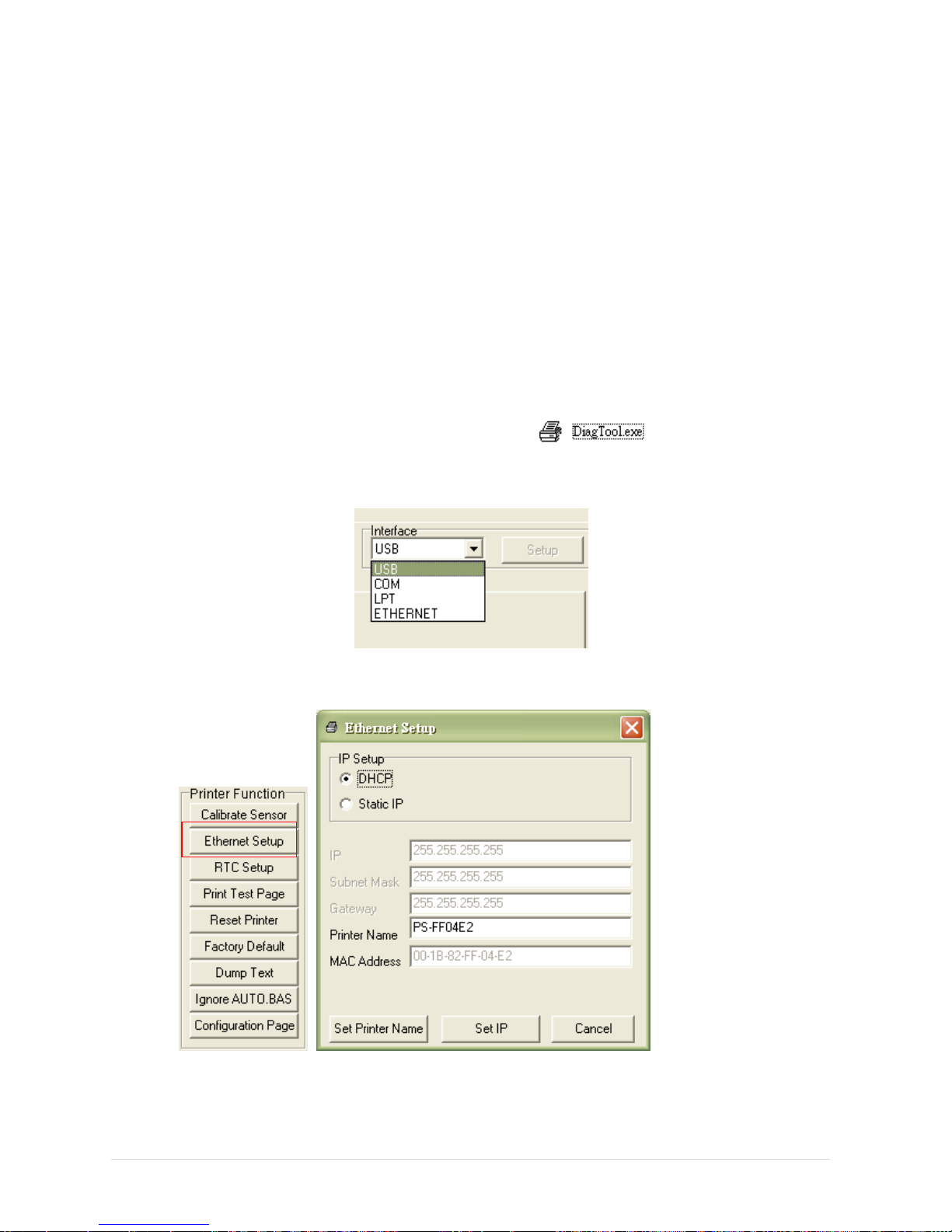
7.3.1 Using USB interface to setup Ethernet interface
1. Connect the printer and computer with USB cable.
2. Turn on the printer power switch.
3. Start the Diagnostic Utility by double clicking on the icon.
4. The Diagnostic Utility default interface setting is USB interface. If USB interface is connected with
printer, no other settings need to be changed in the interface field.
5. Click on the “Ethernet Setup” button from “Printer Function” group in Printer Configuration tab to
setup the IP address, subnet mask and gateway for the on board Ethernet.
Page 79
- 72 -
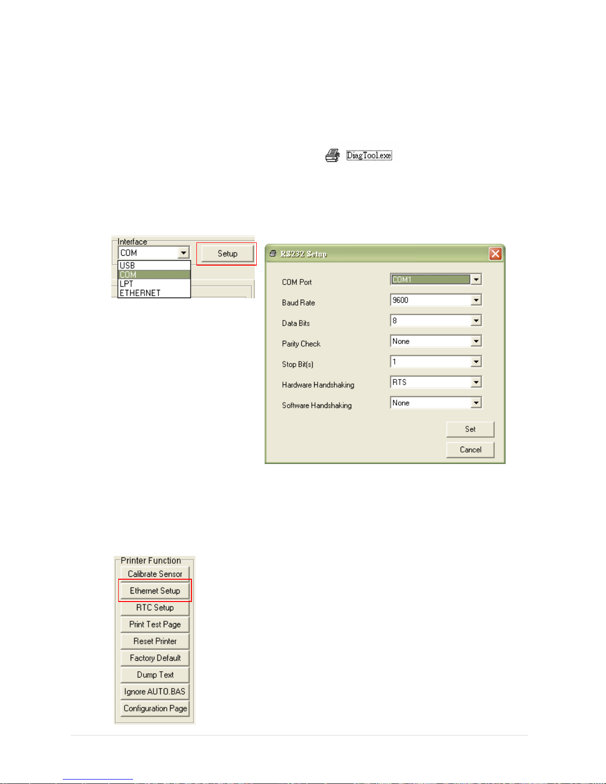
7.3.2 Using RS-232 interface to setup Ethernet interface
1. Connect the computer and the printer with a RS-232 cable.
2. Turn on the printer power.
3. Start the Diagnostic Utility by double clicks on the icon.
4. Select “COM” as interface then click on the “Setup” button to setup the serial port baud rate, parity
check, data bits, stop bit and flow control parameters.
5. Click on the “Ethernet Setup” button from printer function of Printer Configuration tab to setup the IP
address, subnet mask and the gateway for the on board Ethernet.
Page 80
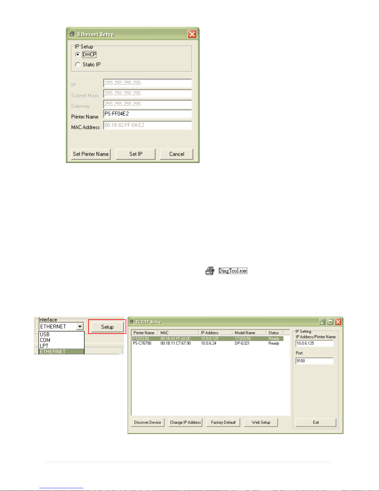
- 73 -
6.3.3 Using Ethernet interface to setup Ethernet interface
1. Connect the computer and the printer to the LAN.
2. Turn on the printer power.
3. Start the Diagnostic Utility by double clicks on the icon.
4. Select “Ethernet” as the interface then click on the “Setup” button to setup the IP address, subnet
mask and gateway for the on board Ethernet.
5. Click the “Discover Device” button to explore the printers that exist on the network.
Page 81
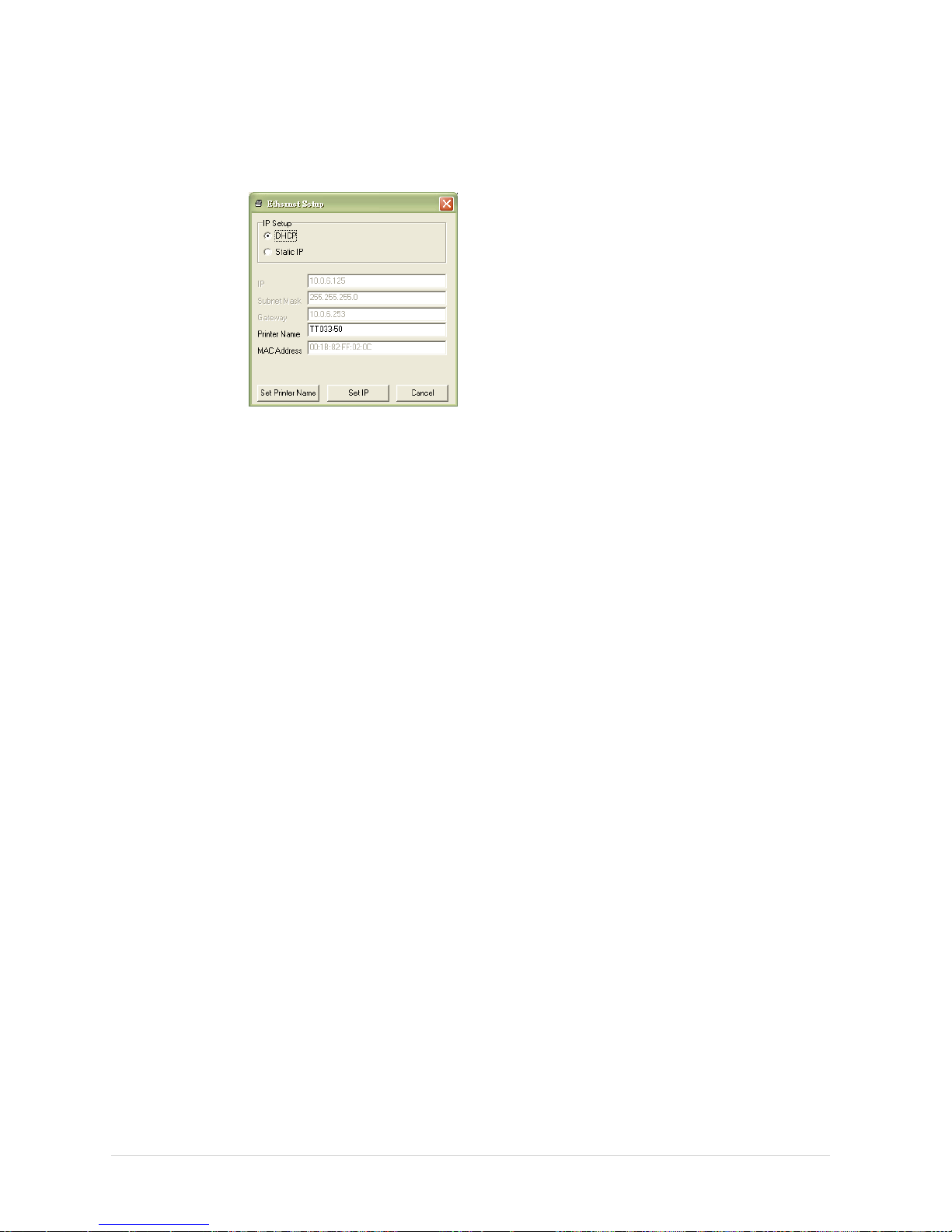
- 74 -
6. Select the printer in the left side of listed printers, the correspondent IP address will be shown in the
right side “IP address/Printer Name” field.
7. Click “Change IP Address” to configure the IP address obtained by DHCP or static.
The default IP address is obtained by DHCP. To change the setting to static IP address, click “Static
IP” radio button then enter the IP address, subnet mask and gateway. Click “Set IP” to take effect the
settings.
Users can also change the “Printer Name” by another model name in this fields then click “Set Printer
Name” to take effect this change.
Note: After clicking the “Set Printer Name” or “Set IP” button, printer will reset to take effect
the settings.
8. Click “Exit” button to exit the Ethernet interface setup and go back to Diagnostic Tool main screen.
Factory Default button
This function will reset the IP, subnet mask, gateway parameters obtained by DHCP and reset the
printer name.
Web setup button
Except to use the Diagnostic Utility to setup the printer, you can also explore and configure the printer
settings and status or update the firmware with the IE or Firefox web browser. This feature provides a
user friendly setup interface and the capability to manage the printer remotely over a network.
Page 82

- 75 -
8. Troubleshooting
The following guide lists the most common problems that may be encountered when operating
this bar code printer. If the printer still does not function after all suggested solutions have been
invoked, please contact the Customer Service Department of your purchased reseller or
distributor for assistance.
Problem
Possible Cause
Recovery Procedure
Power indicator does not
illuminate
* The power cord is not
properly connected.
* Plug the power cord in printer and outlet.
* Switch the printer on.
Carriage Open
* The printer carriages are
open.
* Please close the print carriages.
Not Printing
* Check if interface cable is
well connected to the
interface connector.
* Check if wireless or Bluetooth
device is well connected
between host and printer.
* The port specified in the
Windows driver is not correct.
* Re-connect cable to interface or chang a
new cable.
* Please reset the wireless device setting.
* Select the correct printer port in the
driver.
* Clean the printhead.
* Printhead’s harness connector is not well
connected with printheat. Turn off the
printer and plug the connector again.
* Check your program if there is a
command PRINT at the end of the file
and there must have CRLF at the end of
each command line.
No print on the label
* Label or ribbon is loaded not
correctly.
* Use wrong type paper or
ribbon
* Follow the instructions in loading the
media and ribbon.
* Ribbon and media are not compatible.
* Verify the ribbon-inked side.
* The print density setting is incorrect.
No Ribbon
* Running out of ribbon.
* The ribbon is installed
incorrectly.
* Supply a new ribbon roll.
* Please refer to the steps in user’s
manual to reinstall the ribbon.
No Paper
* Running out of label.
* The label is installed
incorrectly.
* Gap/black mark sensor is not
calibrated.
* Supply a new label roll.
* Please refer to the steps in user’s
manual to reinstall the label roll.
* Calibrate the gap/black mark sensor.
Paper Jam
* Gap/black mark sensor is not
set properly.
* Make sure label size is set
properly.
* Labels may be stuck inside
the printer mechanism.
* Calibrate the media sensor.
* Set media size correctly.
* Remove the stuck label inside the printer
mechanism.
Take Label
* Peel function is enabled.
* If the peeler module is installed, please
remove the label.
* If there is no peeler module in front of
the printer, please switch off the printer
and install it.
* Check if the connector is plugging
correctly.
Can’t downloading the file to
memory (FLASH /
DRAM/CARD)
* The space of memory is full.
* Delete unused files in the memory.
Page 83
- 76 -
SD card is unable to use
* SD card is damaged.
* SD card doesn’t insert
correctly.
* Use the non-approved SD
card manufacturer.
* Use the supported capacity SD card.
* Insert the SD card again.
* The supported SD card spec and the
approved SD card manufacturers,
please refer to section 2.2.3.
Poor Print Quality
* Ribbon and media is loaded
incorrectly
* Dust or adhesive
accumulation on the print
head.
* Print density is not set
properly.
* Printhead element is
damaged.
* Ribbon and media are
incompatible.
* The printhead pressure is not
set properly.
* Reload the supply.
* Clean the print head.
* Clean the platen roller.
* Adjust the print density and print speed.
* Run printer self-test and check the print
head test pattern if there is dot missing in
the pattern.
* Change proper ribbon or proper label
media.
* Adjust the printhead pressure
adjustment knob.
* The release lever does not latch the
printhead properly.
Missing printing on the left or
right side of label
* Wrong label size setup.
* Set the correct label size.
Gray line on the blank label
* The print head is dirty.
* The platen roller is dirty.
* Clean the print head.
* Clean the platen roller.
Irregular printing
* The printer is in Hex Dump
mode.
* The RS-232 setting is
incorrect.
* Turn off and on the printer to skip the
dump mode.
* Re-set the Rs-232 setting.
Label feeding is not stable
(skew) when printing
* The media guide does not
touch the edge of the media.
* If the label is moving to the right side,
please move the label guide to left.
* If the label is moving to the left side,
please move the label guide to right.
Skip labels when printing
* Label size is not specified
properly.
* Sensor sensitivity is not set
properly.
* The media sensor is covered
with dust.
* Check if label size is setup correctly.
* Calibrate the sensor by Auto Gap or
Manual Gap options.
* Clear the GAP/Black mark sensor by
blower.
Wrinkle Problem
* Printhead pressure is
incorrect.
* Ribbon installation is
incorrect.
* Media installation is incorrect.
* Print density is incorrect.
* Media feeding is incorrect.
* Please refer to the next chapter.
* Please set the suitable density to have
good print quality.
* Make sure the label guide touch the
edge of the media guide.
RTC time is incorrect when
reboot the printer
* The battery has run down.
* Check if there is a battery on the main
board.
The left side printout position
is incorrect
* Wrong label size setup.
* The parameter Shift X in LCD
menu is incorrect.
* Set the correct label size.
* Press [MENU] [SELECT] x 3
[DOWN] x 5 [SELECT] to fine tune the
parameter of Shift X.
Page 84
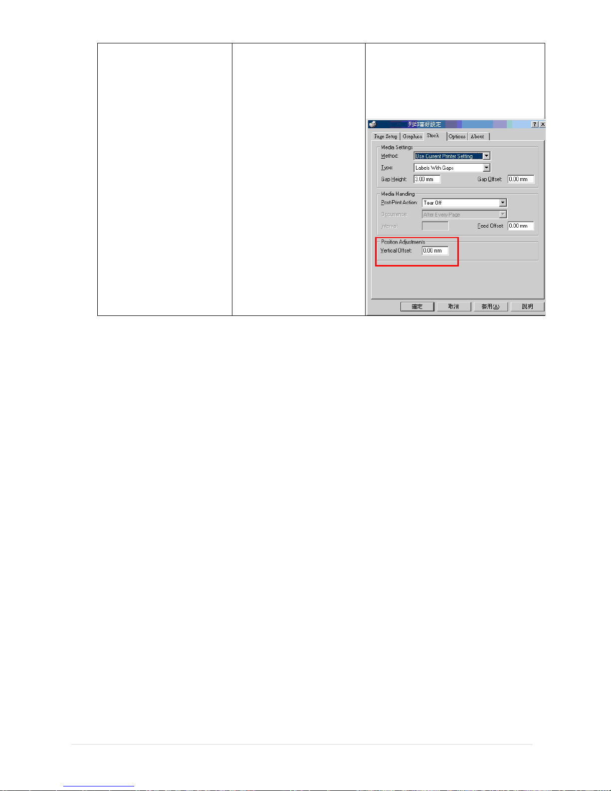
- 77 -
The printing position of small
label is incorrect
* Media sensor sensitivity is
not set properly.
* Label size is incorrect.
* The parameter Shift Y in the
LCD menu is incorrect.
* The vertical offset setting in
the driver is incorrect.
* Calibrate the sensor sensitivity again.
* Set the correct label size and gap size.
* Press [MENU] [SELECT]
x3[DOWN]x6 [SELECT] to fine tune
the parameter of Shift Y.
* If using the software BarTender, please
set the vertical offset in the driver.
Page 85
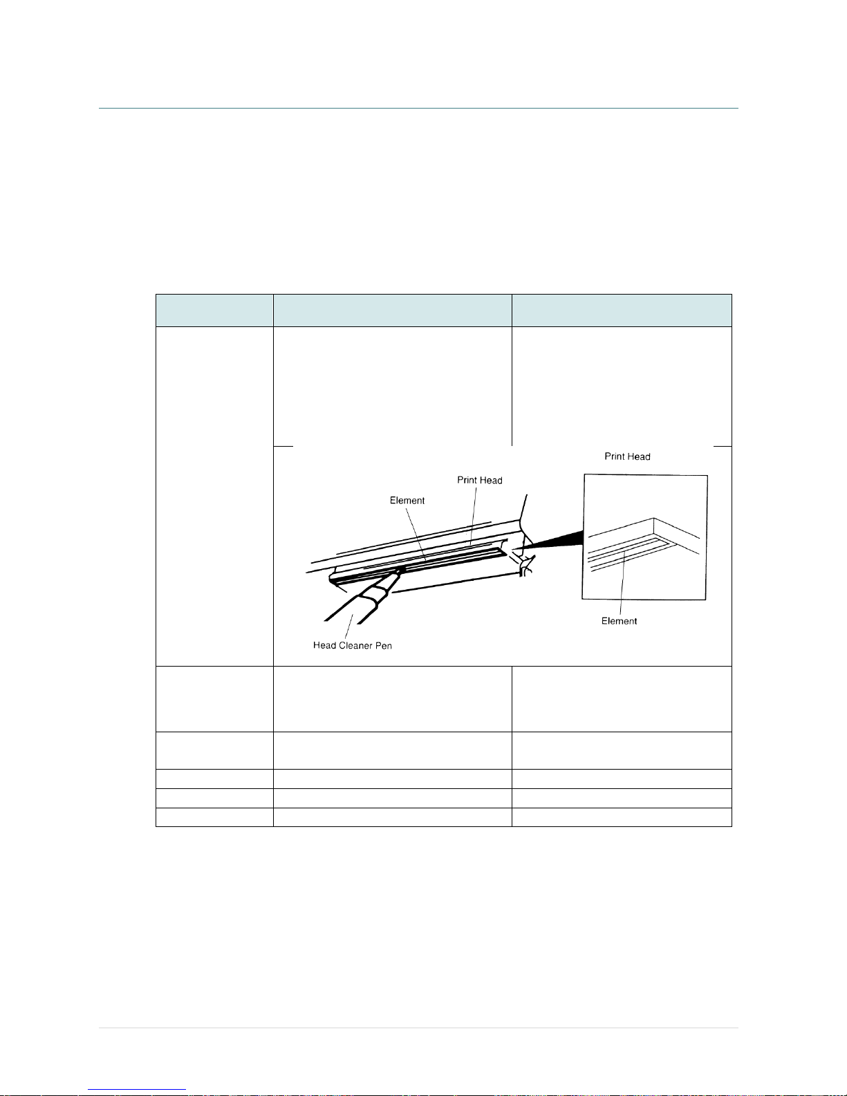
- 78 -
9. Maintenance
This session presents the clean tools and methods to maintain your printer.
1. Please use one of following material to clean the printer.
Cotton swab
Lint-free cloth
Vacuum / Blower brush
100% Ethanol or Isopropyl Alcohol
2. The cleaning process is described as following,
Printer Part
Method
Interval
Print Head
1. Always turn off the printer before
cleaning the print head.
2. Allow the print head to cool for a
minimum of one minute.
3. Use a cotton swab and 100% Ethanol
or Isopropyl Alcohol to clean the print
head surface.
Clean the print head when changing
a new label roll.
Platen Roller
1. Turn the power off.
2. Rotate the platen roller and wipe it
thoroughly with water.
Clean the platen roller when
changing a new label roll
Peel Bar
Use the lint-free cloth with 100% ethanol
to wipe it.
As needed
Sensor
Compressed air or vacuum
Monthly
Exterior
Wipe it with water-dampened cloth
As needed
Interior
Brush or vacuum
As needed
Note:
Do not touch printer head by hand. If you touch it careless, please use ethanol to clean it.
Please use 100% Ethenol or Isopropyl Alcohol. DO NOT use medical alcohol, which may
damage the printer head.
Regularly clean the print head and supply sensors once change a new media to keep printer
performance and extend printer life.
Page 86
- 79 -
Revise History
Date
Content
Editor
2015/6/26
Modify section 1.6
Camille
2015/7/31
Modify section 3.3.3 (Loading media in peel-off mode)
Camille
2015/10/19
Modify section 2.2.3 (Recommended SD card specification)
Camille
Page 87

Corporate Headquarters Li Ze Plant
9F., No.95, Minquan Rd., Xindian Dist., No.35, Sec. 2, Ligong 1st Rd., Wujie Township,
New Taipei City 23141, Taiwan (R.O.C.) Yilan County 26841, Taiwan (R.O.C.)
TEL: +886-2-2218-6789 TEL: +886-3-990-6677
FAX: +886-2-2218-5678 FAX: +886-3-990-5577
Web site: www.tscprinters.com
E-mail: [email protected]
TSC Auto ID Technology Co., Ltd.
 Loading...