

Page 1

SERVICE
MANUAL
TTP-247 / TTP-345
TTP-245 Plus / TTP-343 Plus
THERMAL TRANSFER / DIRECT THERMAL
BAR CODE PRINTER
Page 2

i
Contents
1. FUNDAMENTAL OF THE SYSTEM ..................................................... 1
1.1. Overview ....................................................................................................... 1
1.1.1. Front View .......................................................................................................... 1
1.1.2. Rear View ........................................................................................................... 2
1.2. Specification ................................................................................................. 3
1.2.1. Printer (TTP-245 Plus / TTP-343 Plus) .............................................................. 3
1.2.2. Printer (TTP-247 / TTP-345) ............................................................................. 6
1.2.3. LED .................................................................................................................. 10
1.2.4. Button ............................................................................................................... 10
1.3. Supply Specification .................................................................................. 14
1.3.1. Paper ................................................................................................................. 14
1.3.2. Ribbon .............................................................................................................. 14
2. ELECTRONICS .................................................................................. 15
2.1 Summary of Board Connectors ................................................................. 15
2.2 Pin Configuration ........................................................................................ 19
3. REPLACE IMPORTANT PARTS ........................................................ 21
3.1. Replacing Top Cover .................................................................................. 21
3.2. Replacing Top Inner Cover ........................................................................ 23
3.3. Replacing Lower Cover ............................................................................. 25
3.4. Replacing Main Board ................................................................................ 26
3.5. Replacing Platen Assembly ....................................................................... 27
3.6. Replacing the Stepping Motor Bracket / Metal Assembly and Stepping
Motor .................................................................................................................. 28
3.7. Replacing Label Guide & Gap Sensor Assembly .................................... 30
3.8. Replacing Black Mark Sensor Assembly ................................................. 32
3.9. Replacing Print Head Assembly................................................................ 33
3.10. Replacing Head Open Micro Switch ....................................................... 34
3.11. Replacing Ribbon Motor and Ribbon Sensor ........................................ 36
3.12. Replacing Feed Button and Feed Button PCB ....................................... 38
3.13. Install SD Memory Card ................................ ................................ ........... 39
3.14. Install Peel off Module (Option) ............................................................... 41
3.15. Loading the Label in Peel-off Mode ........................................................ 43
3.16. Install Cutter Module (Option) ................................................................. 45
3.17. Loading Label in Cutter Mode ................................................................. 49
3.18. Internal Ethernet Interface Installation (Option) .................................... 50
4. Power on Utilities .............................................................................. 52
Page 3

ii
4.1 Ribbon and Gap/Black Mark Sensor Calibration ...................................... 52
4.2 Gap/Black Mark Calibration;Self-test;Dump mode .............................. 53
4.3 Printer Initialization ..................................................................................... 56
4.4 Black Mark Sensor Calibration ................................................................... 57
4.5 Gap Sensor Calibration .............................................................................. 57
4.6 Skip AUTO.BAS ........................................................................................... 57
5. GAP AND BLACK MARK SENSOR SELECTION ............................. 59
6. BIOS Update ...................................................................................... 59
7. DIAGNOSTIC TOOL .......................................................................... 60
7.1 Start the Diagnostic Tool ............................................................................ 60
7.2 Printer Function (Calibrate sensor, Ethernet setup, RTC setup………) .. 61
8. TROUBLESHOOTING ....................................................................... 62
9. MAINTENANCE ................................................................................. 66
UPDATE HISTORY ................................................................................ 68
Page 4

1
1. FUNDAMENTAL OF THE SYSTEM
1.1. Overview
1.1.1. Front View
Fig. 1.1.1 Front View
Top Cover Open Lever
Ribbon Access Window
Feed Button
LED Indicator
Label Roll Capacity
View Window
Page 5

2
1.1.2. Rear View
Fig. 1.1.2 Rear View
1. USB Interface
2. Centronics Interface
3. RS-232 Interface
4. Power Jack
5. Power Switch
6. Rear Paper Guide
1 2 3 4 5
6
Page 6

3
1.2. Specification
1.2.1. Printer (TTP-245 Plus / TTP-343 Plus)
Item
Printer model
TTP-245 Plus
TTP-343 Plus
Resolution
203 DPI
300 DPI
Printing method
Thermal Transfer & Direct Thermal
Print speed
2, 3, 4, 5 ips.
2, 3 ips for peel model
2, 3 ips
Max. print width
108 mm (4.25”)
104 mm (4.09”)
Max. print length
2286 mm (90”)
1016 mm (40”)
Enclosure
Double-walled plastic
Physical dimension
314mm (L) x 213mm (W) x 188mm (H)
Ribbon capacity
300 meter, 1” core
Label roll capacity
5” OD
Processor
32-bit RISC high performance processor
Memory
2MB Flash memory
8MB DRAM
SD card slot for memory expansion
Interface
RS-232 (max. 115200 bps)
Centronics
USB 2.0 (Full speed mode)
Power
External universal switching power supply
Input: AC 100-240V
Output: DC 24V 3.75A
Operation switch, button
One power switch & feed button
Sensors
Gap transmissive sensor (offset 6 mm from liner
edge)
Black mark reflective sensor (position adjustable)
Head open
Ribbon end sensor
Page 7

4
Internal font
8 alpha-numeric bitmap fonts
One Monotype Imaging® CG Triumvirate Bold
Condensed scalable font
Code Page
Codepage 437 (English - US)
Codepage 850 (Latin 1)
Codepage 852 (Latin 2)
Codepage 860 (Portuguese)
Codepage 863 (French Canadian)
Codepage 865 (Nordic)
Codepage 857 (Turkish)
Codepage 861 (Iceland)
Codepage 1250 (Latin 2)
Codepage 1251 (Cyrillic)
Codepage 1252 (Latin 1)
Codepage 1253 (Greek)
Codepage 1254 (Turkish)
Codepage 1257 (Baltic)
Codepage 1258 (Vietnam)
ISO-8859-1: Latin-1 (Western European)
ISO-8859-2: Latin-2 (Central European)
ISO-8859-3: Latin-3 (South European)
ISO-8859-4: Latin-4 (North European)
ISO-8859-5: Cyrillic
ISO-8859-7: Greek
ISO-8859-9: Turkish
ISO-8859-10: Nordic
ISO-8859-15: Latin9
Bar code
1D bar code
Code 39, Code 93, Code128UCC, Code128 subset A,
B, C, Codabar, Interleave 2 of 5, EAN-8, EAN-13,
EAN-128, UPC-A, UPC-E, EAN and UPC 2(5) digits
add-on, MSI, PLESSEY, POSTNET, China POST
2D bar code
PDF-417, Maxicode, DataMatrix, QR code
Font & barcode rotation
0, 90, 180,270 degree
Command set
TSPL-EZ
Page 8

5
Media type
Continuous, die-cut, black mark, fan-fold, notch
Media wound type
Outside wound
Media width
20~112mm (0.78" ~ 4.4")
Media thickness
0.06~0.19 mm (2.3~7.4 mil), max. 150g/m2
Media core diameter
25.4~76.2 mm (1”~3”)
Label length
Min. 10 mm (0.4”)
Label length (peeler mode)
25.4~152.4 mm (1”~6”)
Label length (cutter mode)
25.4~2286 mm (1”~90”)
25.4~1016mm (1”~40”)
Gap height
Min. 2 mm
Black mark height
Min. 2 mm
Black mark width
Min. 8 mm (0.31”)
Printout bias
Vertical: 1 mm max.
Horizontal: 1 mm max.
Environment condition
Operation: 5~40oC, 25~85% non-condensing
Storage: -40~60oC, 10~90% non-condensing
Safety regulation
FCC Class B, CE Class B, C-Tick Class B, UL, CUL,
TÜ V/GS, CCC
Accessories
BarTender UltraLite CD disk
Quick start guide
USB cable
External universal switching power supply
Power Cord
Label Spindle, fixing tab x2, 1.5” core adapter x2
Ribbon spindle x2
Ribbon rewind spindle paper core
Reliability
TPH: 1 million inches or 12 months, which comes
first since delivery from TSC (service part)
Platen: 50 km (service part)
Factory option
Real time clock
Page 9

6
Dealer option
Peel off module assembly.
Guillotine cutter
Full cut:
Paper thickness: 0.06~ 0.19mm, 500,000 cuts
Partial cut:
Paper thickness: 0.06~0.12mm, 500,000 cuts
Paper thickness: 0.19mm 200,000 cuts
Main board integrated with internal Ethernet
Internal Ethernet print server module
User option
KP-200
KU-007 plus
External Ethernet print server
External wireless (802.11b/g) print server
External roll mount, media OD. 214 mm (8.4”) with 3”
core label spindle
Contact CCD contact scanner
Long range linear image bar code scanner
1.2.2. Printer (TTP-247 / TTP-345)
Item
Printer model
TTP-247
TTP-345
Resolution
203 DPI
300 DPI
Printing method
Thermal Transfer & Direct Thermal
Print speed
2, 3, 4, 5, 6, 7 ips.
2, 3 ips for peeler mode
2, 3, 4, 5 ips
2 ips for peeler mode
Max. print width
108 mm (4.25”)
106 mm (4.17”)
Max. print length
2286 mm (90”)
1016 mm (40”)
Enclosure
Double-walled plastic
Physical dimension
314mm (L) x 213mm (W) x 188mm (H)
Ribbon capacity
300 meter, 1” core
Label roll capacity
5” OD
Page 10

7
Processor
32-bit RISC high performance processor
Memory
4MB Flash memory
8MB SDRAM
SD card reader for memory expansion
Interface
RS-232 (max. 115200 bps)
Centronics
USB 2.0 (Full speed mode)
Power
External universal switching power supply
Input: AC 100-240V
Output: DC 24V 3.75A
Operation switch, button
One power switch
One feed button
One LED (3 colors green, amber, red)
Sensors
Gap transmissive sensor (offset 6 mm from liner
edge)
Black mark reflective sensor (position adjustable)
Head open
Ribbon end sensor
Internal font
8 alpha-numeric bitmap fonts
One Monotype Imaging® CG Triumvirate Bold
Condensed scalable font
Build-in Monotype True Type Font Engine
Page 11

8
Code Page
Codepage 437 (English - US)
Codepage 850 (Latin 1)
Codepage 852 (Latin 2)
Codepage 860 (Portuguese)
Codepage 863 (French Canadian)
Codepage 865 (Nordic)
Codepage 857 (Turkish)
Codepage 950 (Traditional Chinese)
Codepage 936 (Simplified Chinese)
Codepage 932 (Japanese)
Codepage 949 (Korean)
Codepage 1250 (Latin 2)
Codepage 1251 (Cyrillic)
Codepage 1252 (Latin 1)
Codepage 1253 (Greek)
Codepage 1254 (Turkish)
Codepage 1257 (Baltic)
Codepage 1258 (Vietnam)
ISO-8859-1: Latin-1 (Western European)
ISO-8859-2: Latin-2 (Central European)
ISO-8859-3: Latin-3 (South European)
ISO-8859-4: Latin-4 (North European)
ISO-8859-5: Cyrillic
ISO-8859-7: Greek
ISO-8859-9: Turkish
ISO-8859-10: Nordic
ISO-8859-15: Latin9
Bar code
1D bar code
Code 39, Code 93, Code128UCC, Code128 subsets
A.B.C, Codabar, Interleave 2 of 5, EAN-8, EAN-13,
EAN-128, UPC-A, UPC-E, EAN and UPC 2(5) digits
add-on, MSI, PLESSEY, POSTNET, RSS-Stacked,
RSS14, Code 11, China Post
2D bar code
PDF-417, Maxicode, DataMatrix, QR code, Aztec
Font & barcode rotation
0, 90, 180,270 degrees
Command set
TSPL-EZTM
Page 12

9
Media type
Continuous, die-cut, black mark, fan-fold, notch
Media wound type
Outside wound
Media width
20~112mm (0.78" ~ 4.4")
Media thickness
0.06~0.19 mm (2.3~7.4 mil), max. 150g/m2
Media core diameter
25.4~76.2 mm (1”~3”)
Label length
Min. 10 mm (0.4”)
Label length (peeler mode)
25.4~152.4 mm (1”~6”)
Label length (cutter mode)
25.4~2286 mm (1”~90”)
25.4~1016mm (1”~40”)
Gap height
Min. 2 mm
Black mark height
Min. 2 mm
Black mark width
Min. 8 mm (0.31”)
Printout bias
Vertical: 1 mm max.
Horizontal: 1 mm max.
Environment condition
Operation: 5~40oC (41~140oF), 25~85% non-condensing
Storage: -40~60oC (-40~140oF), 10~90% non-condensing
Safety regulation
FCC Class B, CE Class B, C-Tick Class B, UL, CUL,
TÜ V/Safety, CCC
Accessories
Windows labeling software CD disk
Quick start guide
USB cable
External universal switching power supply
Power Cord
Label Spindle, fixing tab x2, 1.5” core adapter x2
Ribbon spindle x2
Ribbon rewind spindle paper core
Reliability
TPH: 1 million inches or 12 months, which comes
first since delivery from TSC (service part)
Platen: 50 km (service part)
Factory option
Real time clock
Main board integrated with internal Ethernet
Page 13

10
Dealer option
Peel off module assembly.
Guillotine cutter
Full cut:
Paper thickness: 0.06~ 0.19mm, 500,000 cuts
Partial cut:
Paper thickness: 0.06~0.12mm, 500,000 cuts
Paper thickness: 0.19mm 200,000 cuts
User option
KP-200 Plus
KU-007 Plus
HCS-200 long range linear image bar code scanner
Bluetooth module
1.2.3. LED
LED Color
Description
Green/ Solid
This illuminates that the power is on and the device is
ready to use.
Green/ Flash
This illuminates that the system is downloading data
from PC to memory and the printer is paused.
Amber
This illuminates that the system is clearing data from
printer.
Red / Solid
This illuminates printer head open, cutter error.
Red / Flash
This illuminates a printing error, such as paper empty,
paper jam, ribbon empty, or memory error etc.
1.2.4. Button
Feed
Press the button when the LED is green.
It feeds the label to the beginning of the next label.
Pause
Press the feed button during printing
The printing job is suspended.
Page 14

11
Ribbon Sensor and
Gap/Black Mark
Sensor Calibration
1. Turn off the power switch.
2. Hold on the button then turn on the power switch.
3 Release the button when LED becomes red and blinking.
(Any red will do during the 5 blinks).
It will calibrate the ribbon sensor and gap/black
mark sensor sensitivity.
The LED color will be changed as following order:
Amber red (5 blinks) amber (5 blinks)
green (5 blinks) green/amber (5 blinks)
red/amber (5 blinks) solid green
Note:
Please select gap or black mark sensor by GAP or
BLINE command prior to calibrate the sensor.
For more information about GAP and BLINE command,
please refer to TSPL2 programming manual.
Gap/Black Mark
Sensor Calibratio,
Label Length
Measurement, Self
Test and enter Dump
Mode
1.Turn off the power switch.
2. Hold on the button then turn on the power switch.
3. Release the button when LED becomes amber and
blinking. (Any amber will do during the 5 blinks).
The LED color will be changed as following order.
Amber red (5 blinks) amber (5 blinks)
green (5 blinks) green/amber (5 blinks)
red/amber (5 blinks) solid green
It calibrates the sensor and measures the label
length and prints internal settings then enter the
dump mode.
Note:
Please select gap or black mark sensor by GAP or
BLINE command prior to calibrate the sensor.
For more information about GAP and BLINE command,
please refer to TSPL2 programming manual.
Page 15

12
Printer Initialization
1. Turn off the power switch.
2. Hold on the button then turn on the power switch.
3. Release the button when LED turns green after 5 amber
blinks. (Any green will do during the 5 blinks).
The LED color will be changed as following:
Amber red (5 blinks) amber (5 blinks)
green (5 blinks) green/amber (5 blinks)
red/amber (5 blinks) solid green
Note:
Always do gap/black mark sensor calibration after
printer initialization.
Force Black Mark
Sensor Calibration
1. Turn off the power switch.
2. Hold on the button then turn on the power switch.
3. Release the button when LED turns green/amber after 5
green blinks. (Any green/amber will do during the 5
blinks).
The LED color will be changed as following:
Amber red (5 blinks) amber (5 blinks)
green (5 blinks) green/amber (5 blinks)
red/amber (5 blinks) solid green
Force Gap Sensor
Calibration
1. Turn off the power switch.
2. Hold on the button then turn on the power switch.
3. Release the button when LED turns red/amber after 5
green/amber blinks. (Any red/amber will do during the 5
blinks).
The LED color will be changed as following:
Amber red (5 blinks) amber (5 blinks)
green (5 blinks) green/amber (5 blinks)
red/amber (5 blinks) solid green
Page 16

13
Skip AUTO.BAS
1. Turn off printer power.
2. Press the FEED button and then turn on power.
3. Release the FEED button when LED becomes solid
green.
The LED color will be changed as following:
Amber red (5 blinks) amber (5 blinks)
green (5 blinks) green/amber (5 blinks)
red/amber (5 blinks) solid green
4. Printer will be interrupted to run the AUTO.BAS program.
Page 17

14
1.3. Supply Specification
1.3.1. Paper
Item
Specification
Type
Label (Continuous , Die-cut , Fan-fold).
Wound Type
Outside wound.
Width
20~112mm (0.78" ~ 4.4")
Length
( for peel and cutter )
10mm ~ 1000mm (0.4” ~ 39”).
25.4mm ~ 1000mm (1” ~ 39”).
Thickness
0.06mm ~ 0.19mm.
Roll Diameter
5”.
Roll Core Diameter
25.4mm ~ 76.2mm (1” ~ 3”).
Gap Height
2mm min.
Black Mark Height
2mm min.
Black Mark Width
8mm min.
1.3.2. Ribbon
Item
Specification
Type
Wax, Wax / Resin, Resin.
Core Diameter
1".
Width
Max 110mm.
Capacity
300m with 1" core.
Wound Type
Outside wound.
Ribbon End
Clear or silver end tape.
Page 18

15
2. ELECTRONICS
2.1 Summary of Board Connectors
Main board
Top
Connector
Description
Remark
1
Centronics port connector
JP4
2
USB connector
JP9
3
RS-232C connector
JP7
4
Micro processor
U2
5
RFID module connector
JP36
1
2
3 4 5
6
7
7
7
8
9
10
11
12
14
13
15
16
17
18
Page 19

16
6
Head open sensor connector
JP16
Pin
Description
Voltage
1
Head open sensor switch
receiver
0V: Head close
3.3V:Head open
2
GND
0V
7
Gap/Black mark sensor connector
JP39, JP41
JP39
Pin
Description
Voltage
1
Reserved
2
Gap sensor
receiver AD
0~3.3V
3
Power
3.3V
4
Gap sensor
emitter
2.5~3.0V
5
Gap sensor
power
3.0~3.3V
JP41
Pin
Description
Voltage
1
Gap sensor power
3.0~3.3V
2
Black mark sensor
power
3.0~3.3V
3
Black mark sensor
emitter
2.5~3.0V
4
Black mark sensor
receiver AD
0~3.3V
5
Power
3.3V
8
Ribbon sensor connector
JP18
Pin
Description
Voltage
1
Ribbon sensor emitter
On: 3.7~3.9V
Off: 4.3~4.6V
2
Power
5V
3
Ribbon sensor receiver
No ribbon: 0V
With ribbon: 3.3V
4
GND
0V
Page 20

17
9
Ribbon encoder sensor connector
JP37
JP37
Pin
Description
Voltage
1
Power
5V
2
Ribbon encoder
sensor receiver
High: 5V (reflecting)
Low: 0V (non-reflecting)
3
GND
0V
4
DC motor
Work: <23V
No work: 23.4V~24V
5
DC motor
23.4V~24V
10
Cutter connector
JP38
11
Peel-off sensor connector
JP19
Pin
Description
Voltage
1
GND
0V
2
Peel sensor receiver
AD
0~3.3V
3
Peel sensor emitter
Emitter on: 1.0~1.2V
Emitter off: 0V
4
Power
5V 5 Reserved
12
Power supply output (24V DC) connector
B3
13
Power switch
SW2
14
Print head connector
JP42
15
Stepping motor connector
JP14
16
Ethernet connector (Factory option)
JP43
17
LED connector
JP28
Pin
Description
Voltage
1
Power
3.3V
2
LED green
LED light on: 1.1~1.4V
LED light off: 1.6~1.9V
3
LED red
LED light on: 1.4~1.7V
LED light off: 1.8~2.1V
4
Feed switch
0V: Push key
3.3V: Stand-by
5
GND
0V
18
RS-232 pin 9 +5V jumper
JP6
Page 21

18
Main board
Bottom
Connector
Description
Remark
1
Cutter driver IC connector
U30
2
SD card slot
JP2
3
RTC battery (Factory option)
BT2
1
2
3
Page 22

19
2.2 Pin Configuration
RS-232C
PIN
CONFIGURATION
1
+5 V
2
TXD
3
RXD
4
CTS
5
GND
6
RTS
7
N/C
8
RTS
9
N/C
USB
PIN
CONFIGURATION
1
N/C 2 D- 3 D+
4
GND
Centronics
Pin
SPP Mode
Nibble
In/Out
Function
1
Strobe
N/A
In
A low on this line indicates that there are valid
data at the host. When this pin is de-asserted,
the +ve clock edge should be used to shift the
data into the device.
2-9
Data 0-7
N/A
In
Data Bus. Single-directional.
10
Ack
N/A
Out
A low on this line indicates that there are valid
data at the Device. When this pin is
de-asserted, the +ve clock edge should be
used to shift the data into the host.
11
Busy
N/A
Out
When in reverse direction, a high indicates
data, while a low indicates a command cycle.
In forward direction, it functions as PtrBusy.
Page 23
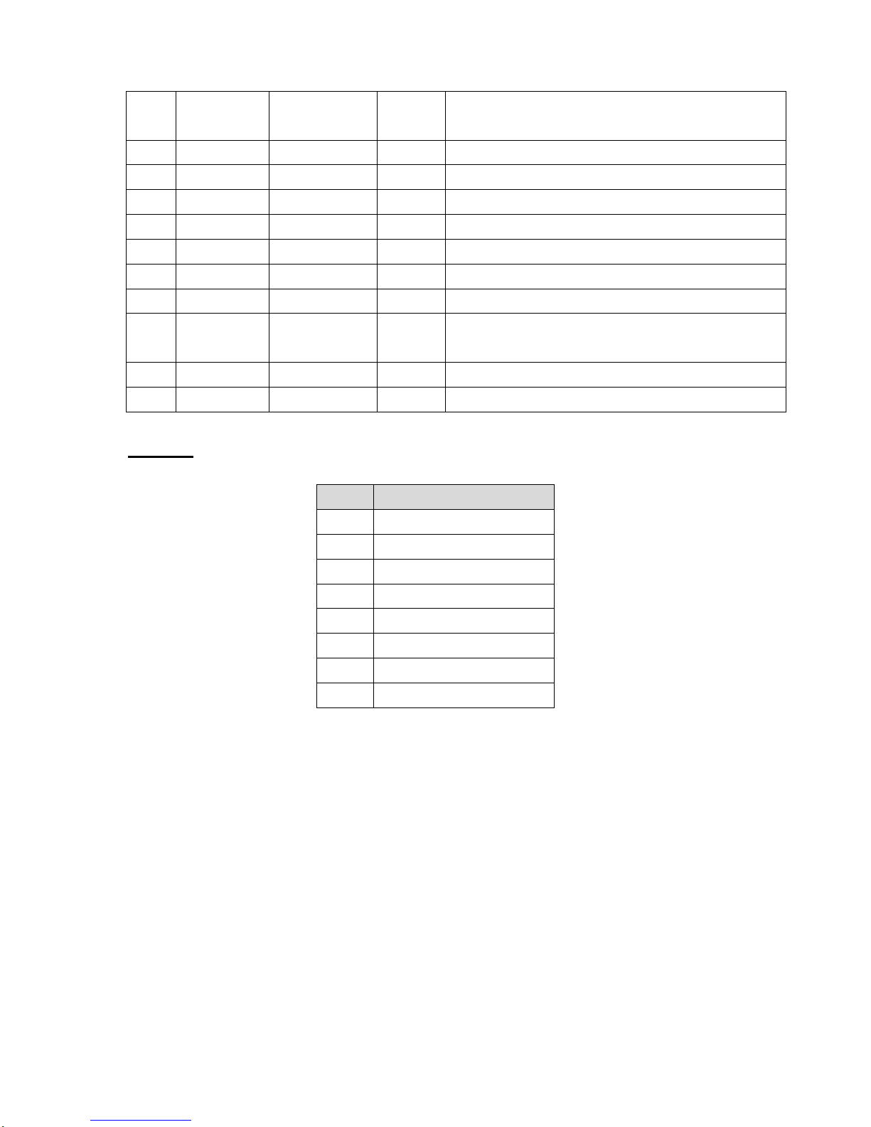
20
12
Paper Out /
End
N/A
Out
When low, device acknowledges reverse
request.
13
Select
N/A
Out
Extensibility flag
14
Ground
N/A
GND
15
No Defined
N/A
N/A
16-17
Ground
N/A
GND
Ground
18
No Defined
N/A
N/A
19-30
Ground
N/A
GND
Ground
31
No Defined
N/A
N/A
32
Error / Fault
N/A
Out
A low set by the device indicates that the
reverse data is available
33-35
Ground
N/A
GND
Ground
36
No Defined
N/A
N/A
Ethernet
PIN
CONFIGURATION
1
Tx+
2
Tx-
3
Rx+
4
N/C
5
N/C
6
Rx-
7
N/C
8
N/C
Page 24
21
3. REPLACE IMPORTANT PARTS
Please turn off the power switch and unplug the power adapter before replacing parts.
3.1. Replacing Top Cover
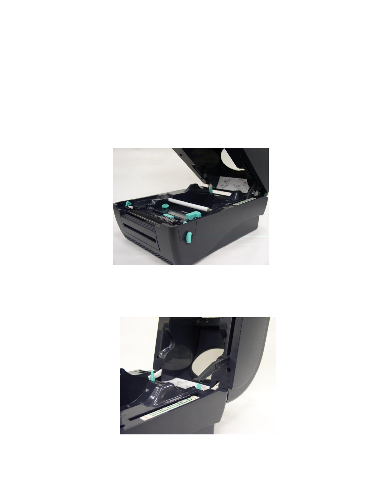
1. Open the printer top cover by pushing the top cover open levers to the
paper outlet direction. The top cover support will hold the printer top cover.
2. Open the top cover to the ultimate open angle. Push the top cover support to
the communication port direction to disconnect the separate the lower inner
cover and top cover support.
Top cover support
Top cover open
lever
Page 25
22
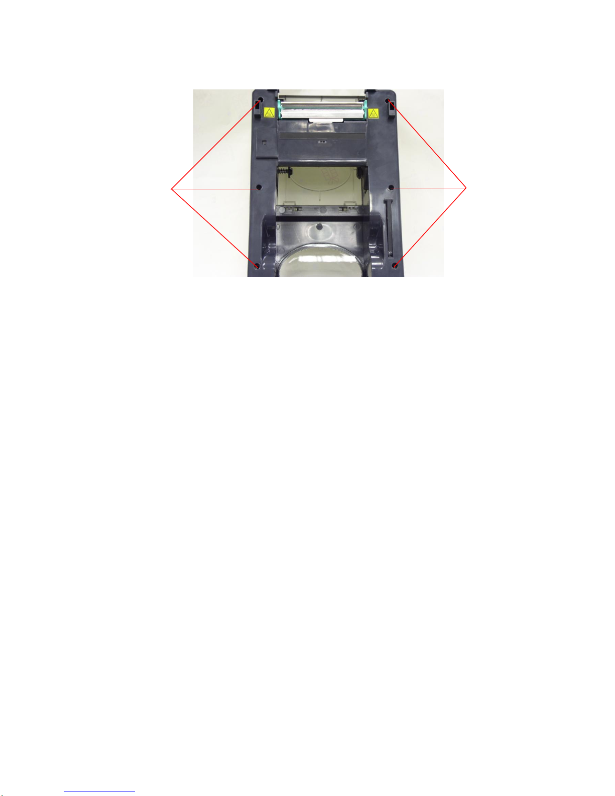
3. Remove the 6 screws in the top inner cover.
4. Disconnect the harness from the Feed button PCB. Replace the top cover.
5. Reassemble parts in reverse procedures.
Screws
Screws
Page 26
23
3.2. Replacing Top Inner Cover
1. Refer 3.1 to remove the top cover.
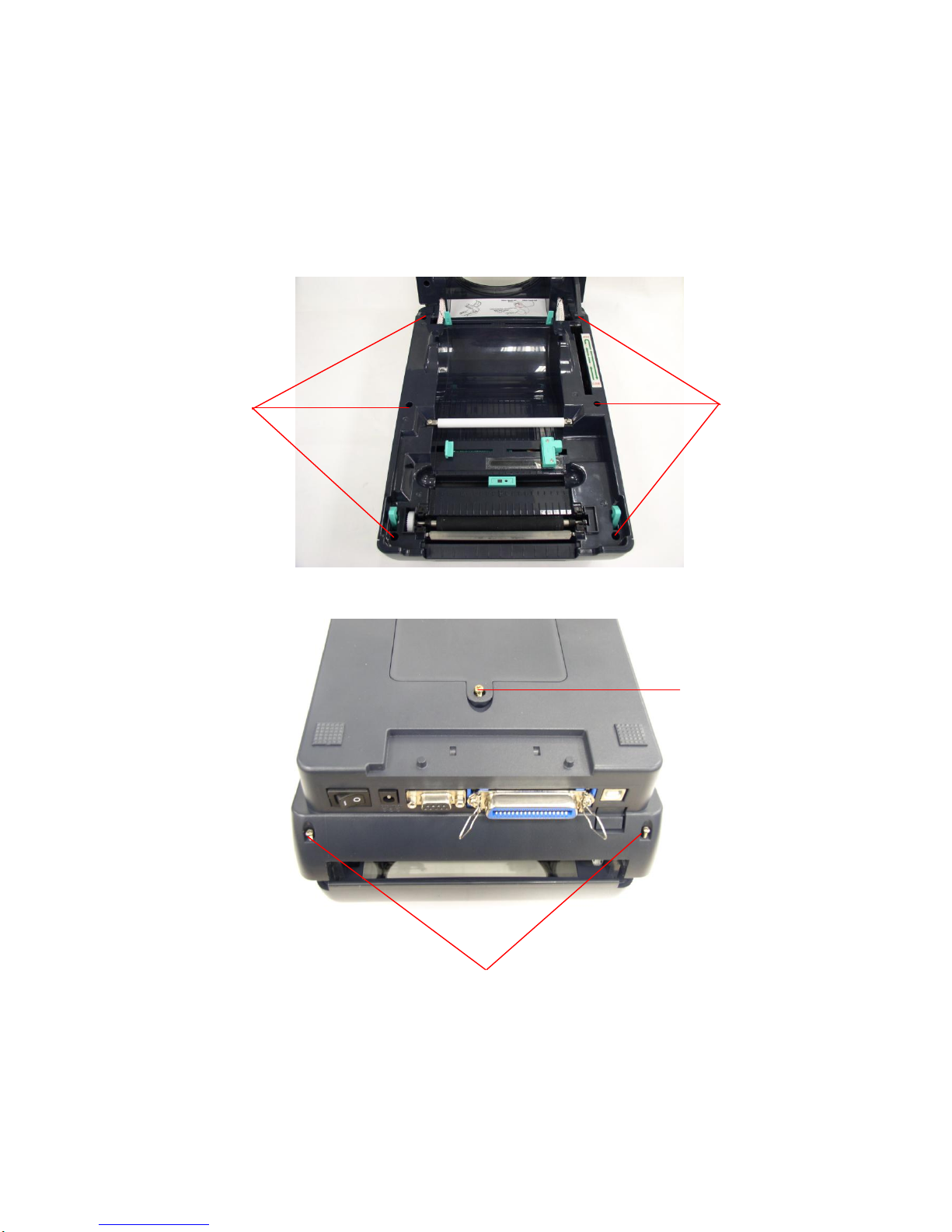
2. Remove the 6 screws of lower inner cover. Turn the printer upside down, and
remove the 2 screws of hinge holder, 1 screw of memory card cover.
3. Disconnect all the harnesses from Main Board. Lift up the lower inner cover.
Turn the lower inner cover upside down, and remove the 6 screws of lower
inner cover and hinge holders.
2 screws of hinge holder
Screw of memory
card cover
Screws
Screws
Page 27

24
4. Replace the top inner cover.
5. Reassemble in reverse procedures.
Page 28
25
3.3. Replacing Lower Cover
1. Refer to 3.1 to open the top cover.
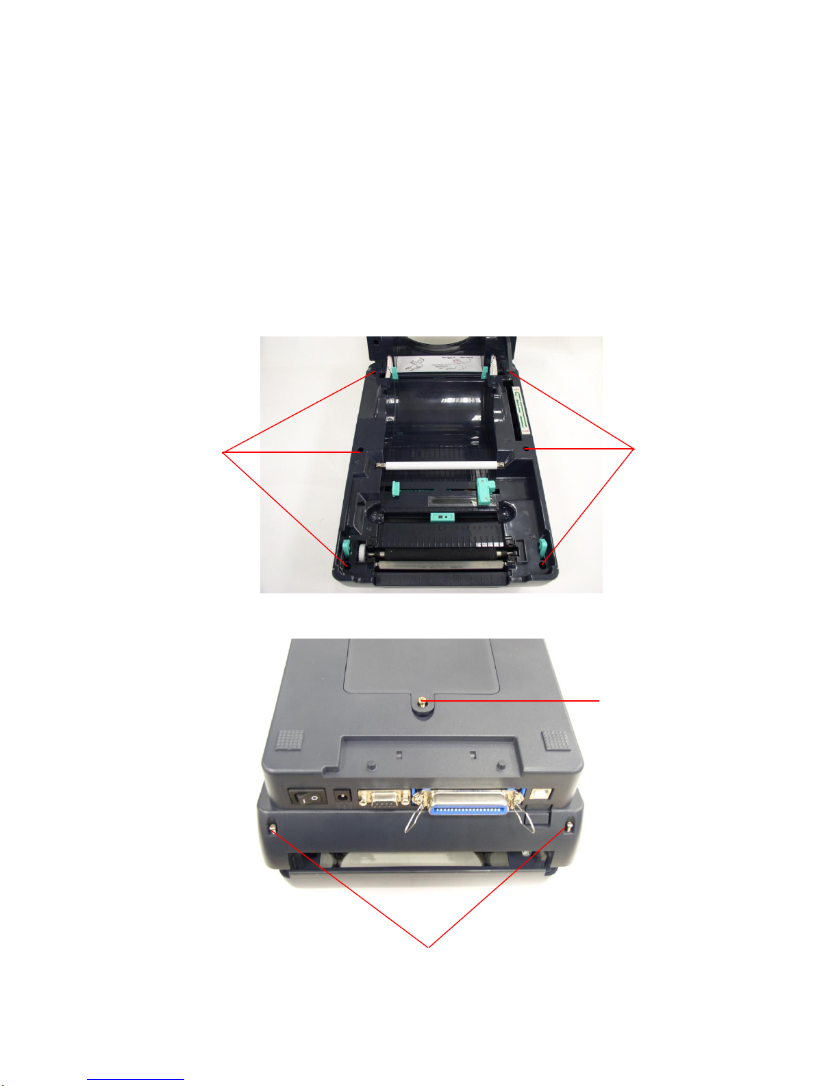
2. Remove the 6 screws of lower inner cover. Turn the printer upside down, and
remove the 2 screws of hinge holder, 1 screw of memory card cover.
Screws
Screws
2 screws of hinge holder
Screw of memory
card cover
Page 29
26
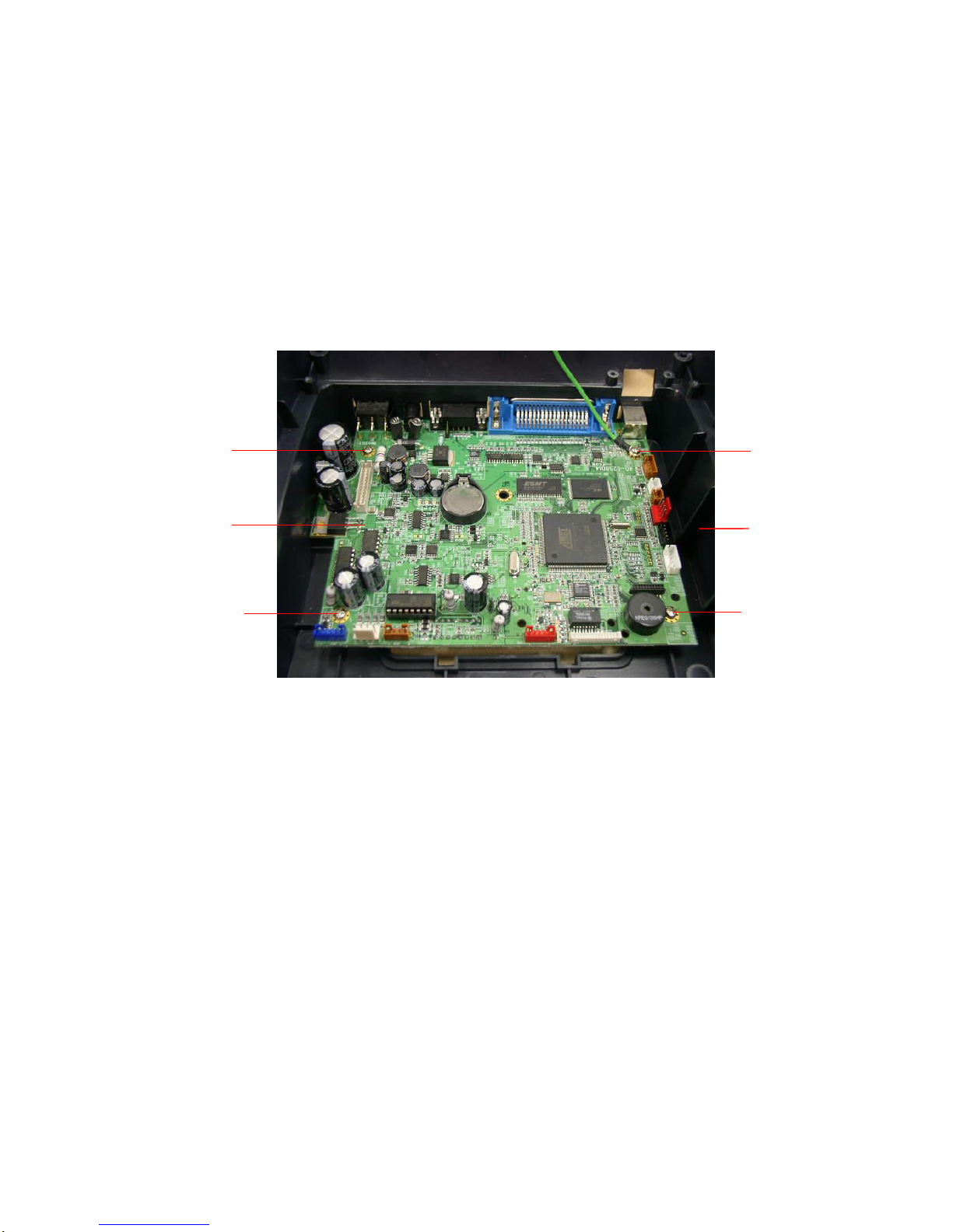
3. Disconnect all the harnesses from Main Board. Lift up the lower inner cover.
4. Replace lower cover.
5. Reassemble in reverse procedures.
3.4. Replacing Main Board
1. Please refer to 3.3 for disassembling the LOWER COVER and LOWER inner
cover.
2. Disconnect all harnesses.
3. Remove 4 screws on the main board.
4. Replace the main board/lower inner cover.
5. Reassemble parts in reverse procedures.
Screw
Screw
Screw
Screw
Lower Cover
Main Board
Page 30
27
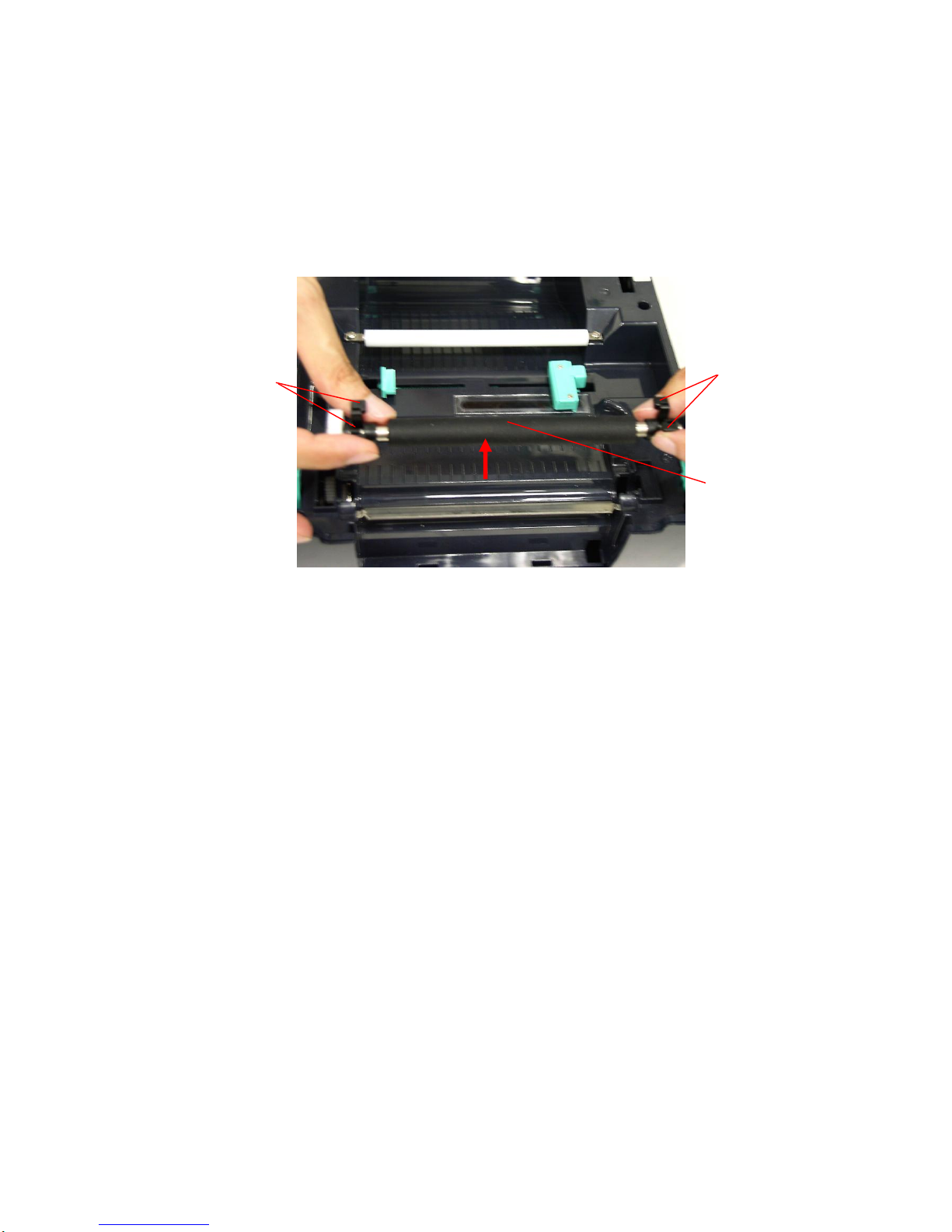
3.5. Replacing Platen Assembly
1. Squeeze two sides of platen assembly and take it out.
2. Replace a platen.
3. Reassemble it in reverse procedures.
Squeeze Here
Platen
Squeeze Here
Page 31
28
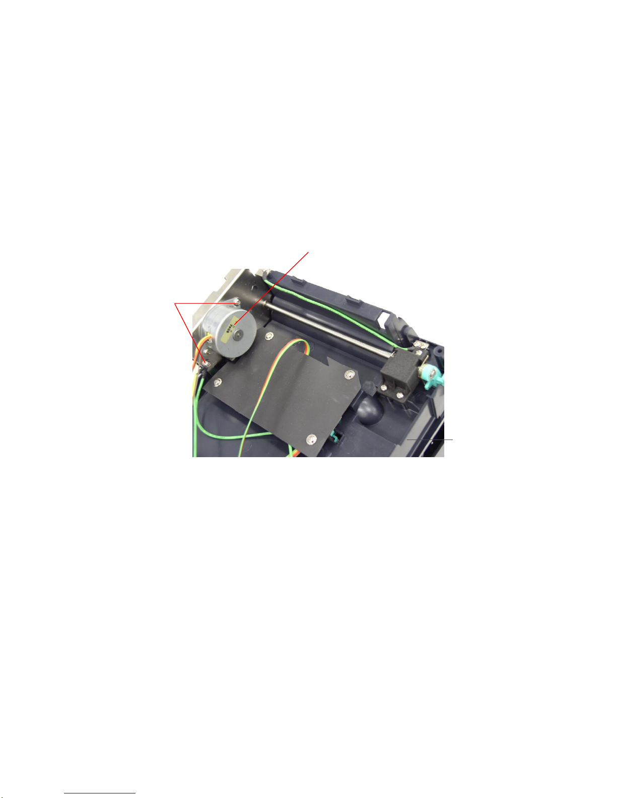
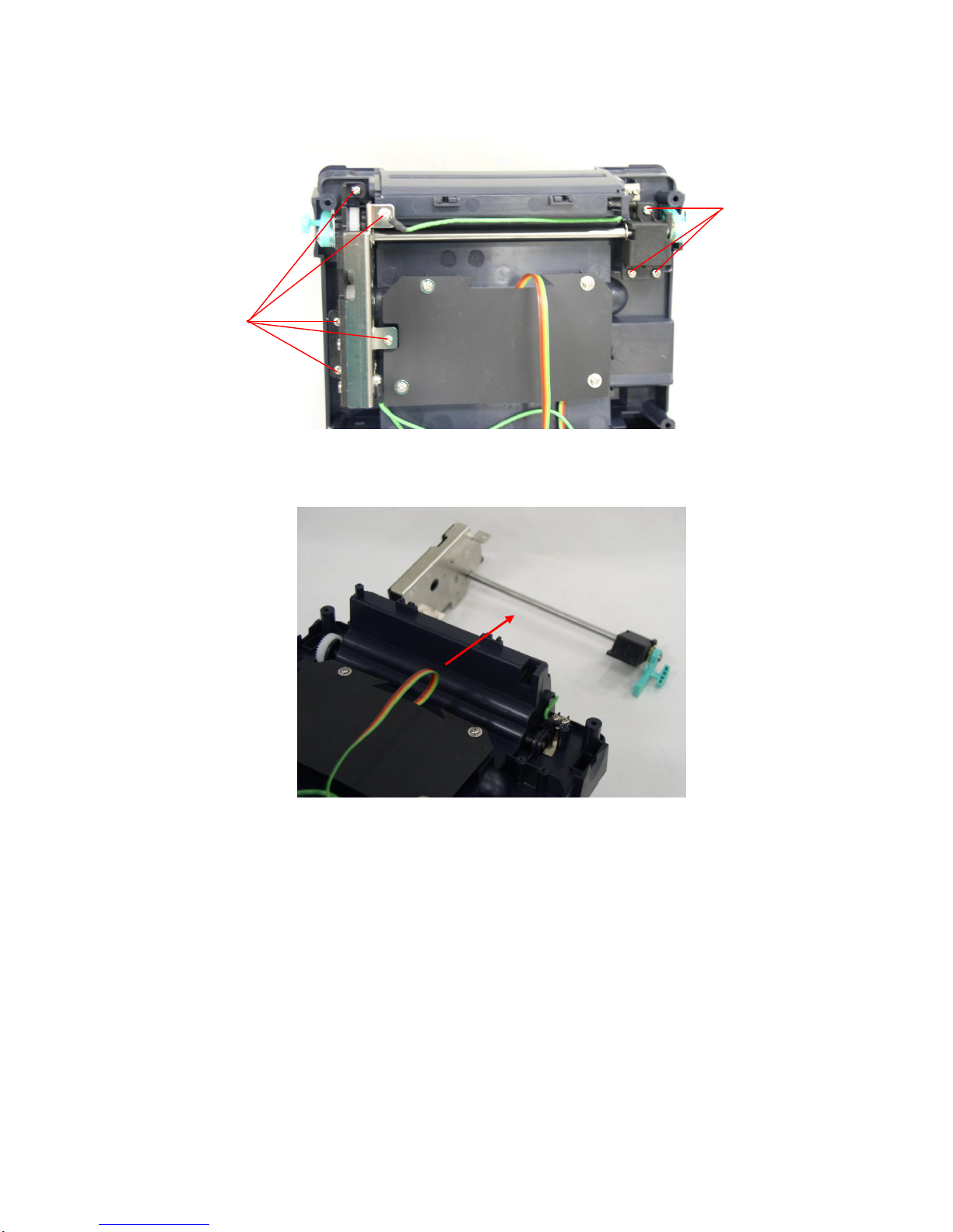
3.6. Replacing the Stepping Motor Bracket / Metal Assembly
and Stepping Motor
1. Please refer to 3.1 for disassembling the lower cover and lower inner cover.
2. Disconnect all hardness.
3. Turn the lower inner cover upside down.
4. Remove 2 screws that fixed the stepping motor on the bracket
5. Remove the stepping motor.
6. Use a screwdriver to screw off 8 screws of the stepping motor bracket /
metal ass’y.
Screws
Motor
Lower inner cover
Page 32
29
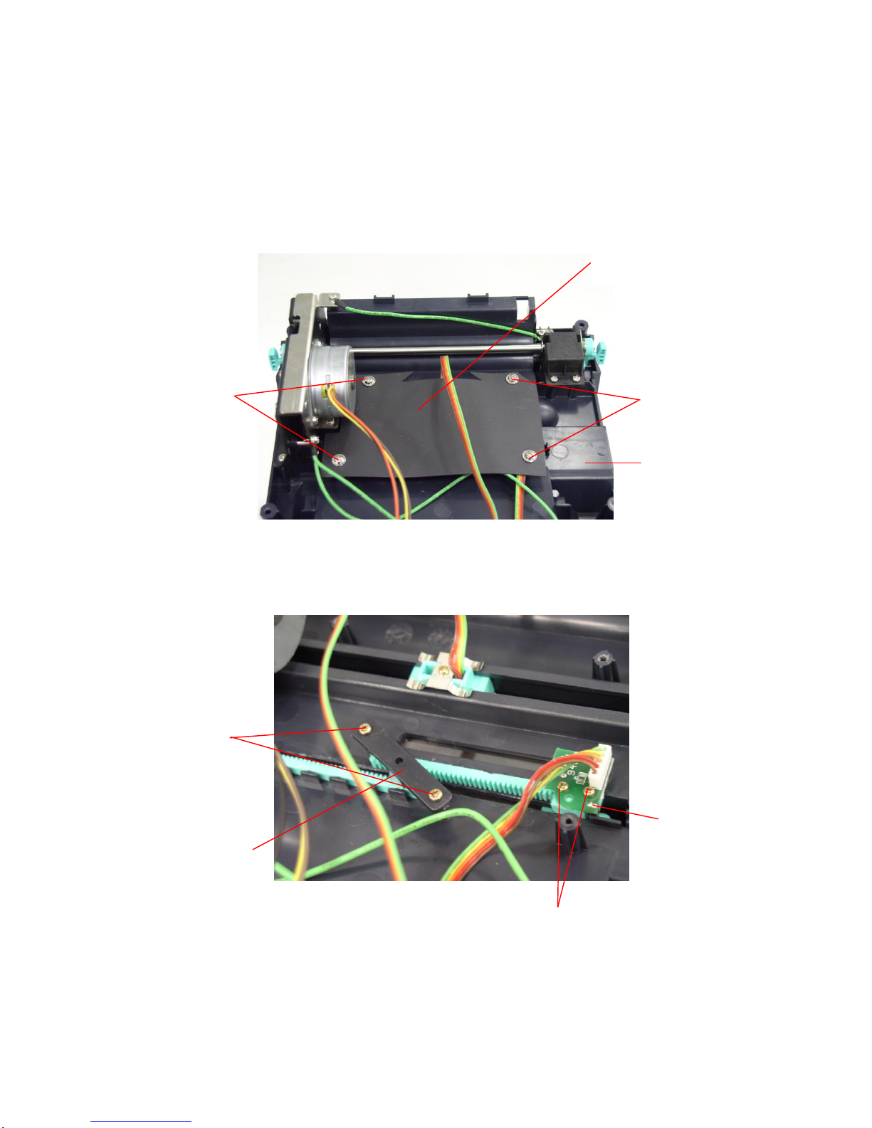
7. Remove the stepping motor bracket / metal ass’y.
8. Reassemble parts in reverse procedures.
Screws
Screws
Page 33
30
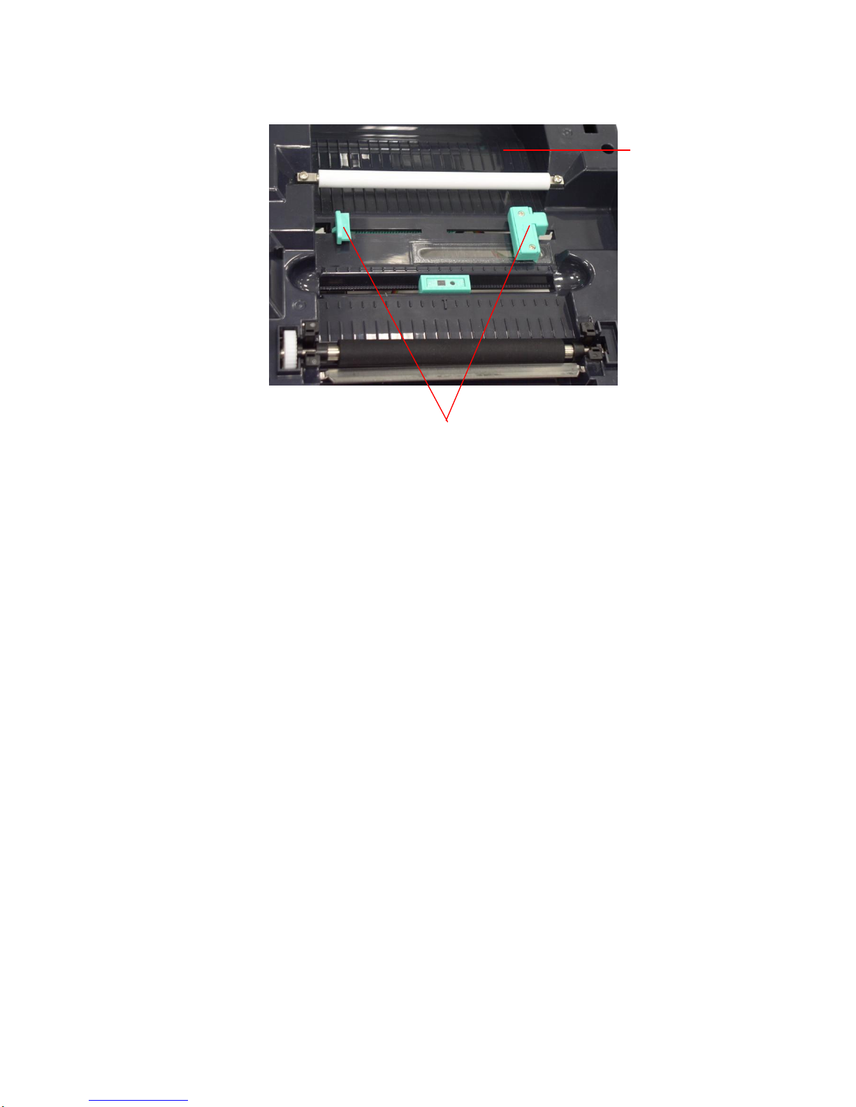
3.7. Replacing Label Guide & Gap Sensor Assembly
1. Please refer to 3.1 for disassembling the lower cover and lower inner cover.
2. Disconnect all the hardness.
3. Turn the lower inner cover upside down.
4. Screws off 4 screws and remove the plastic laminate.
5. Screws off 2 screws to remove the white label guide rack fixing plate
6. Remove 2 screws from a gap sensor PCB then remove the gap sensor PCB.
7. Turn over the lower inner cover.
8. Move right side and left side label guides to the end of each side. Rotates 90
degrees and pull them out.
Screws
Screws
Label Guide
Rack Fixing
Plate
Screw
Gap Sensor
PCB
Plastic Laminate
Lower inner cover
Screws
Page 34
31
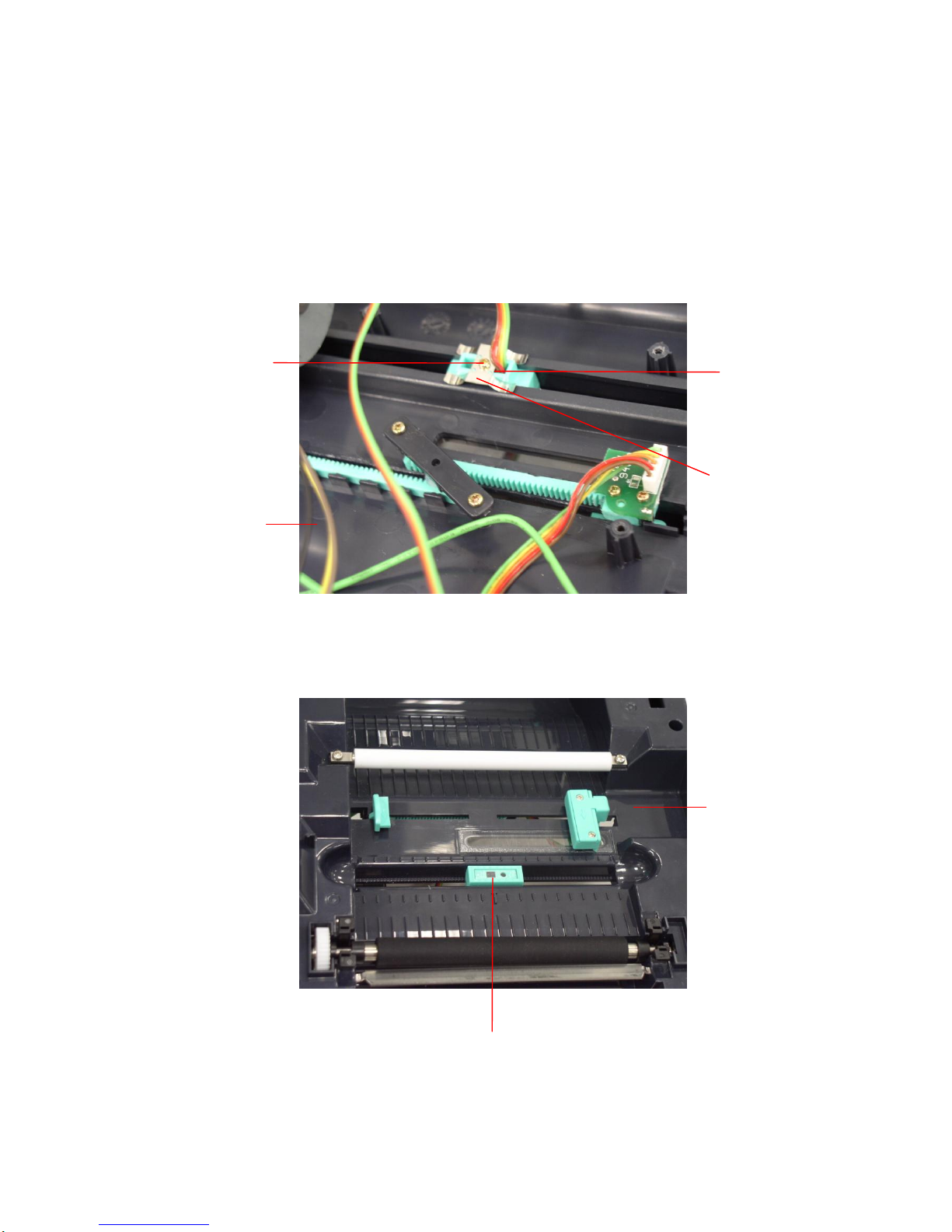
9. Reassemble parts in reverse procedures.
Label Guide
Lower inner cover
Page 35
32
3.8. Replacing Black Mark Sensor Assembly
1. Please refer to 3.1 for disassembling the lower cover and lower inner cover.
2. Disconnect all hardness.
3. Upside down the lower inner cover. Remove 4 screws and remove the plastic
laminate.
4. Remove 1 screw from the black mark sensor.
5. Upside down the lower inner cover.
6. Replace the black mark sensor assembly.
7. Reassemble parts in reverse procedures.
Screw
Black Mark Sensor
Lower inner
cover
Black Mark Sensor
Fixing Plate
Lower inner cover
Black Mark
Sensor
Page 36
33
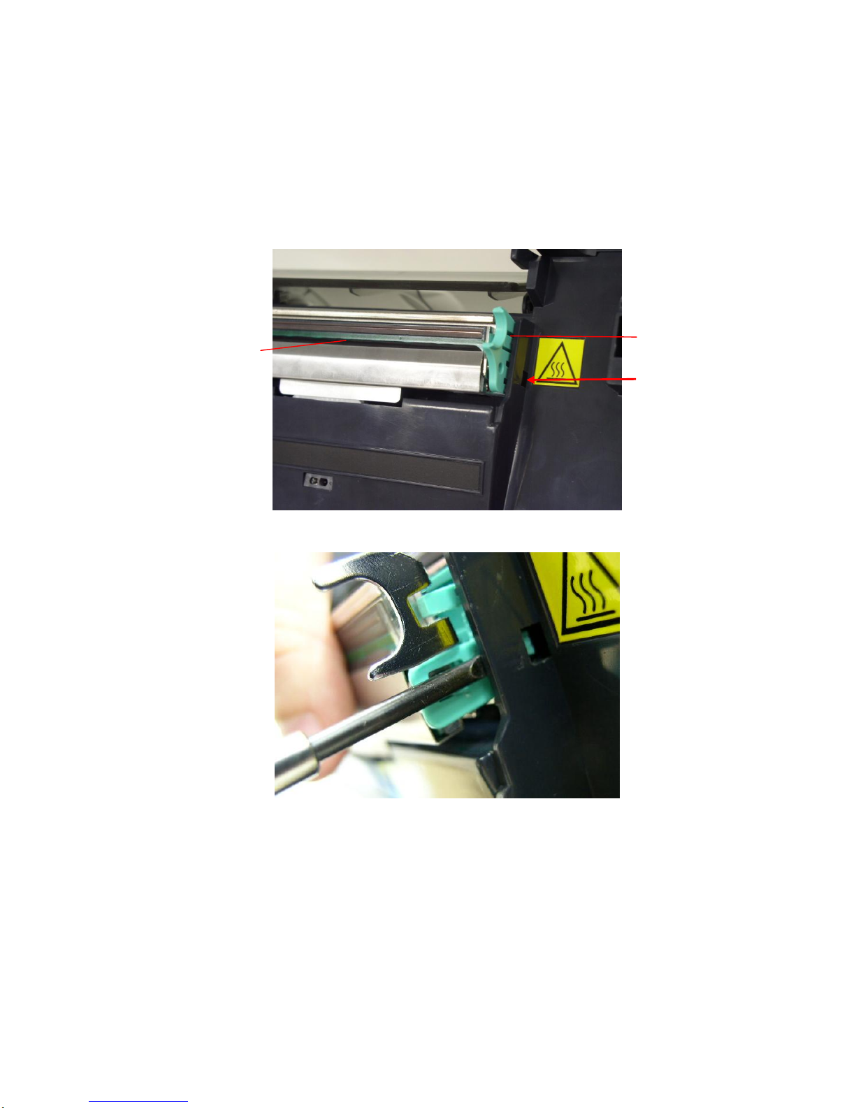
3.9. Replacing Print Head Assembly
1. Press right concave of the print head bracket and use a flat screwdriver to
stick left side of the printer head bracket then pick up the print head assembly.
2. Disconnect print head harnesses.
3. Reassemble parts in reverse procedures.
Bracket Concave
Print Head
Stick Flat
Screwdriver Here
Page 37
34
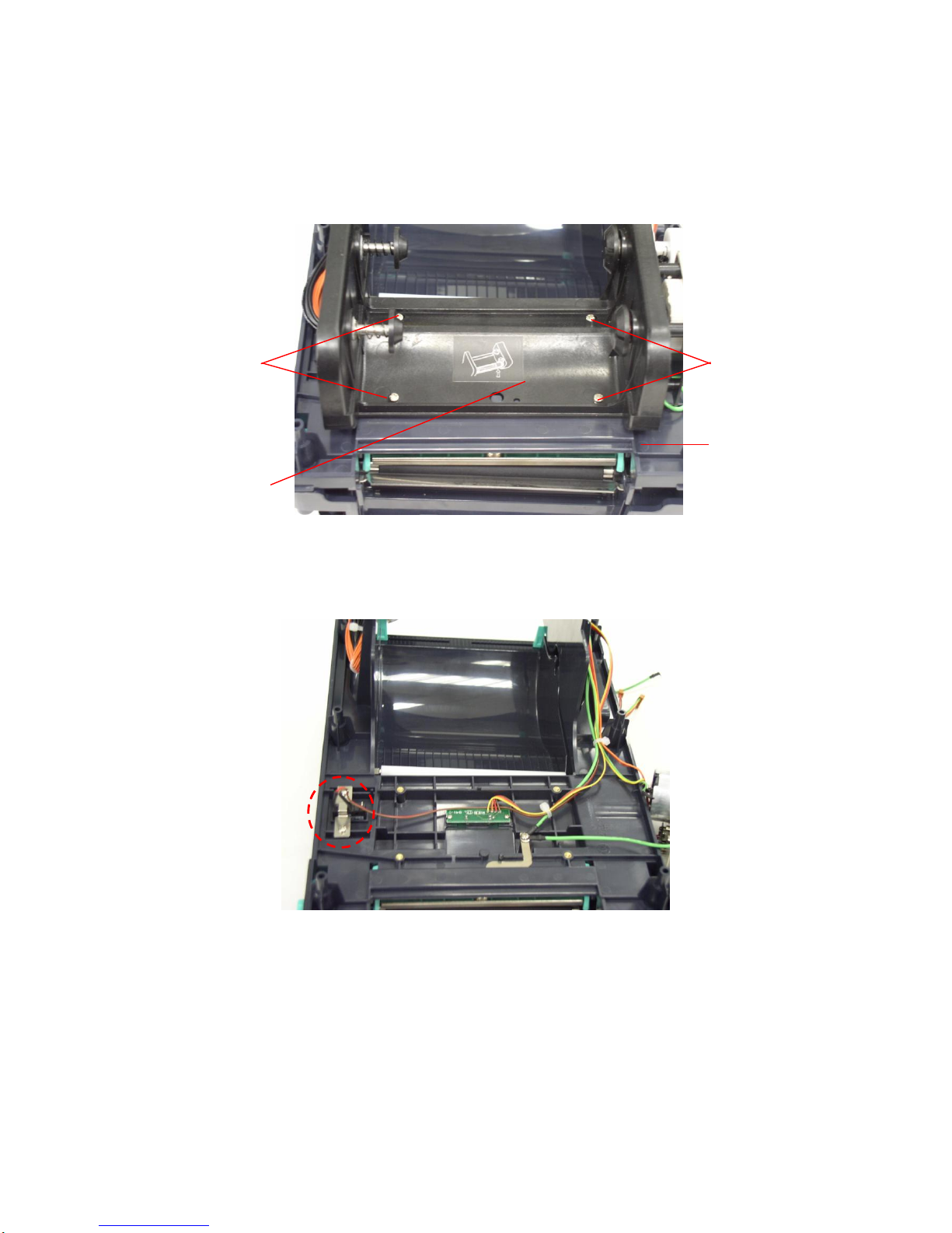
3.10. Replacing Head Open Micro Switch
1. Please refer to 3.1 for disassembling the top cover and top inner cover.
2. Disconnect ribbon mechanism by removing 4 screws at top inner cover.
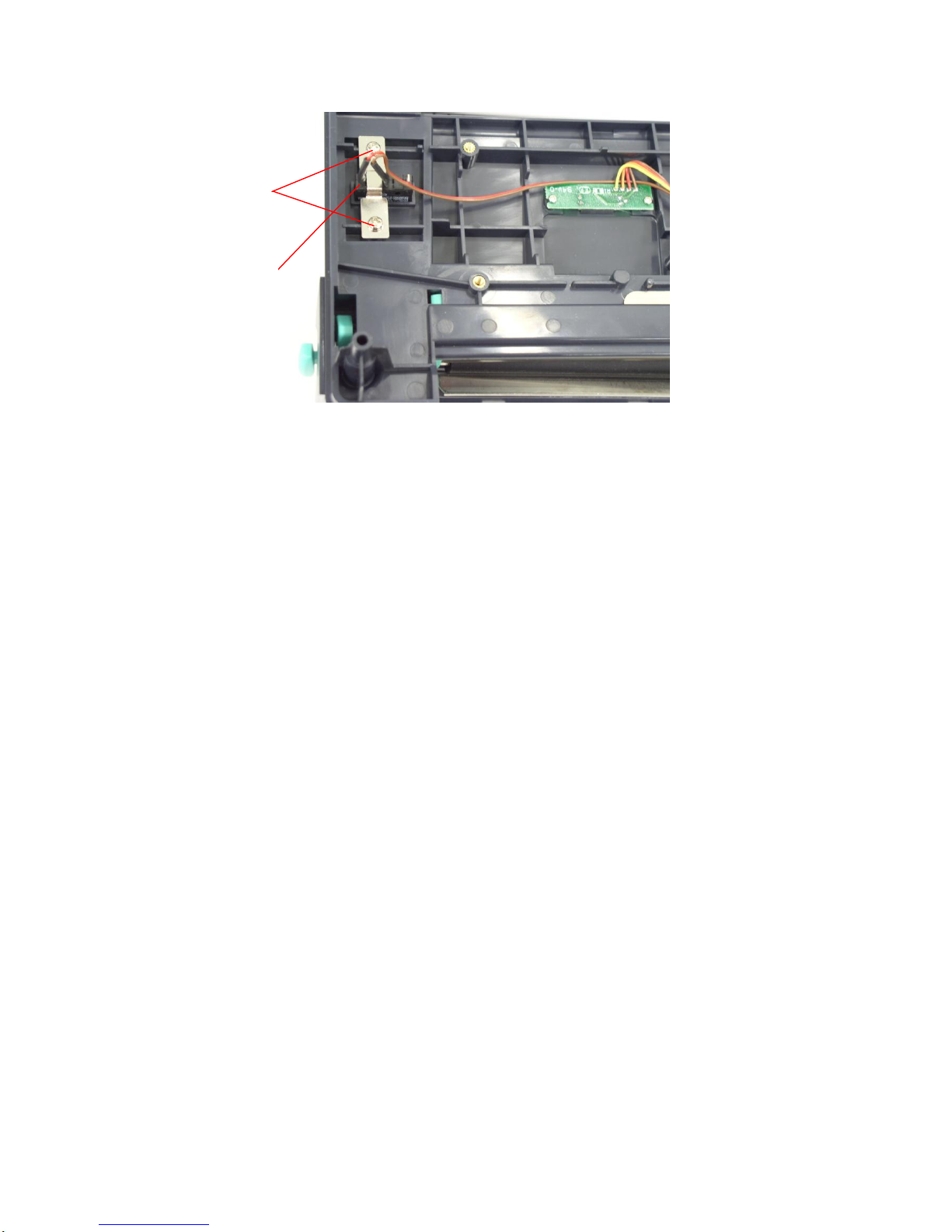
3. Remove 2 screws and remove the head open micro switch.
Mechanism
Screws
Screws
Top inner cover
Page 38
35
4. Reassemble parts in reverse procedures.
Screws
Head Open
Micro Switch
Page 39
36
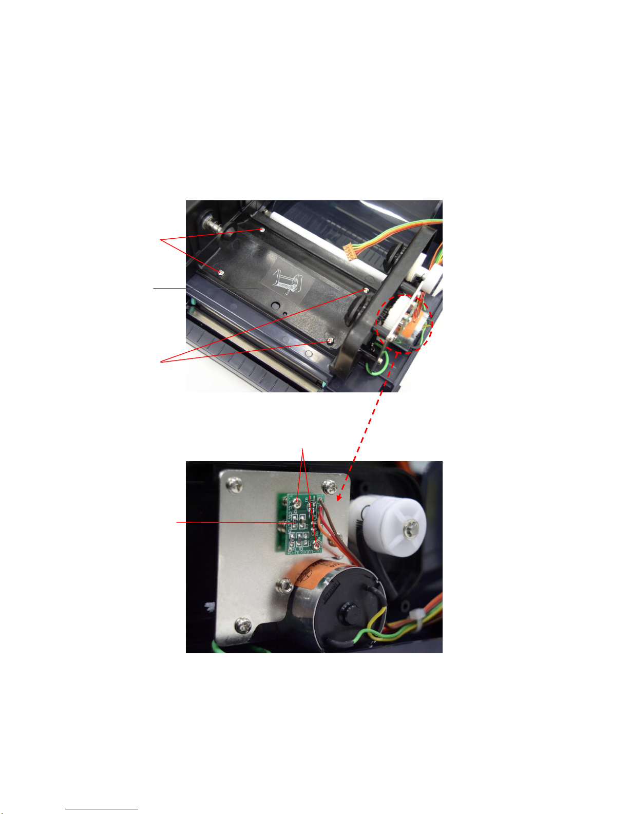
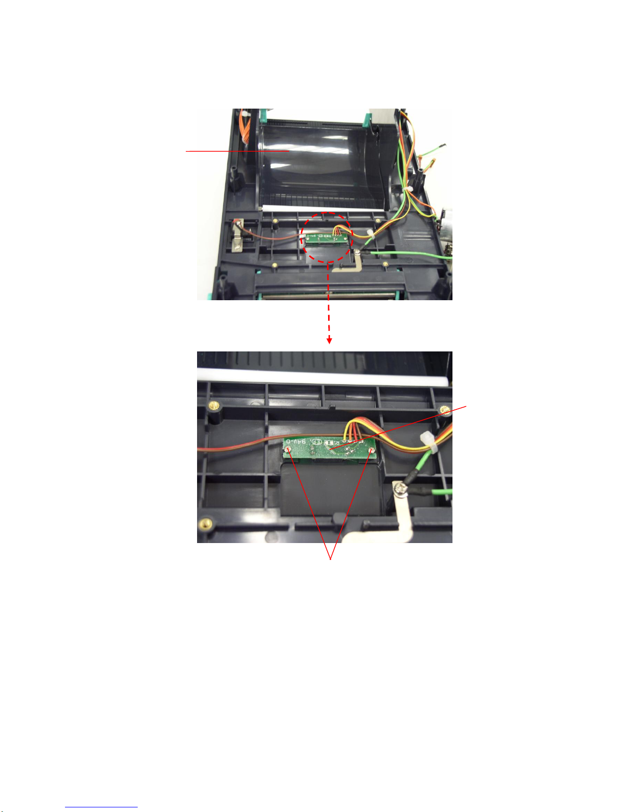
3.11. Replacing Ribbon Motor and Ribbon Sensor
1. Please refer to 3.1 for disassembling the top cover and top inner cover.
2. Disconnect ribbon mechanism by removing 4 screws from the top inner
cover.
3. Remove 2 screws on the ribbon motor PCB.
4. Replace the ribbon motor sensor.
5. Screw off 2 screws from the top inner cover.
6. Replace the ribbon sensor.
7. Reassemble parts in reverse procedures.
Screws
Ribbon
Motor
Sensor
Screws
Screws
Ribbon
Mechanism
Page 40
37
Screws
Ribbon Sensor
Top inner cover
Page 41
38
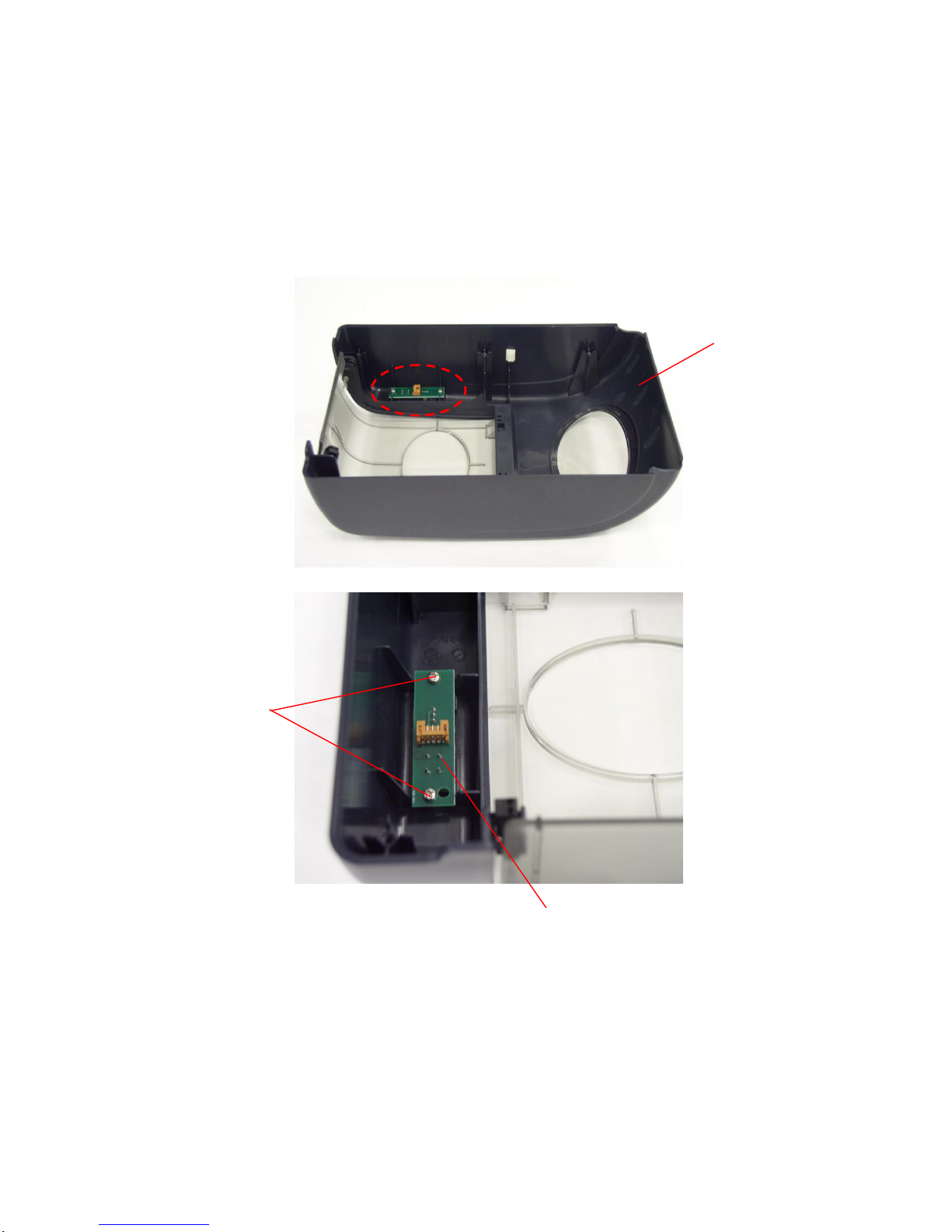
3.12. Replacing Feed Button and Feed Button PCB
1. Please refer to 3.1 for disassembling the top cover and top inner cover.
2. Turn the top cover upside down.
3. Screw off 2 screws on feed button PCB and remove feed button PCB.
4. Use a flat head driver to poke up the feed button.
5. Reassemble parts in reverse procedures.
Screws
Top Cover
Feed Button PCB
Page 42
39
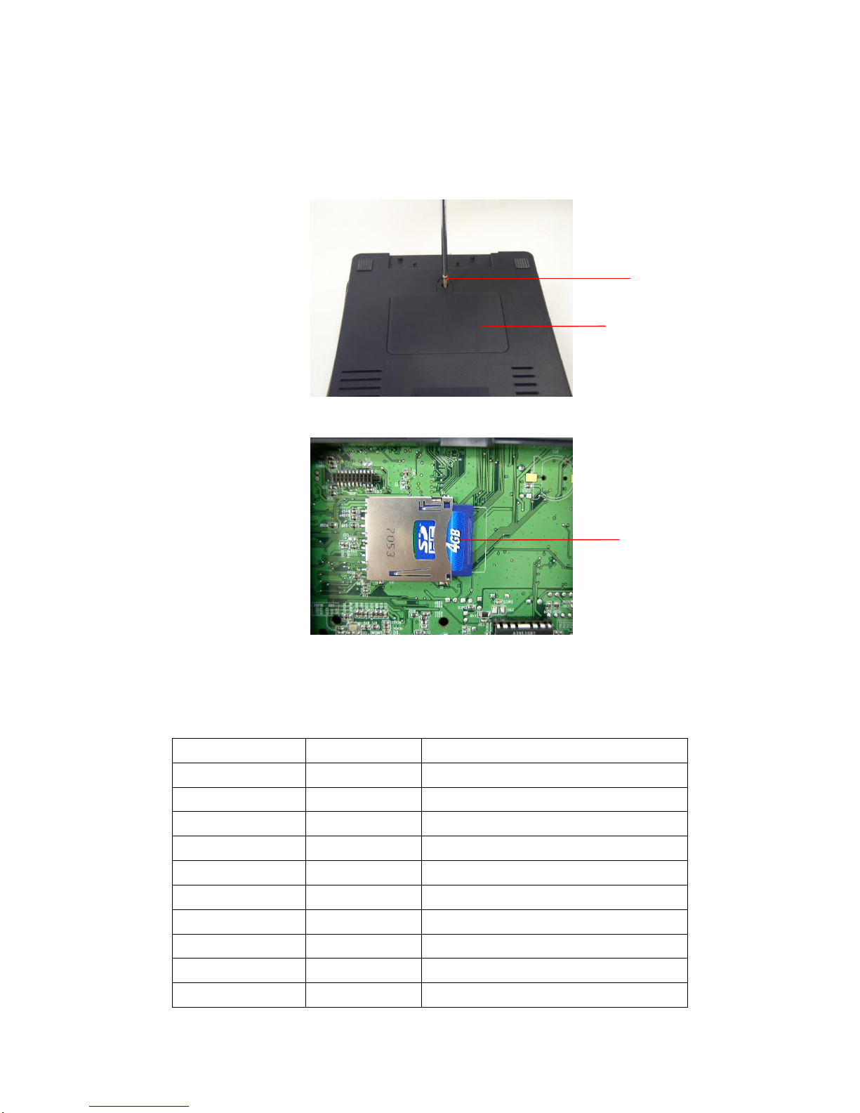
3.13. Install SD Memory Card
1. Turn the printer upside down.
2. Remove the screw that fixes the memory card cover.
3. Plug in a SD card on main board.
4. Revert the memory card cover.
5. Reassemble parts in reverse procedures.
* Recommended SD card specification.
SD card spec
SD card capacity
Approved SD card manufacturer
V1.0, V1.1
128 MB
SanDisk, Transcend
V1.0, V1.1
256 MB
SanDisk, Transcend, Panasonic
V1.0, V1.1
512 MB
SanDisk, Transcend, Panasonic
V1.0, V1.1
1 GB
SanDisk, Transcend, Panasonic
V2.0 SDHC CLASS 4
4 GB
V2.0 SDHC CLASS 6
4 GB
SanDisk, Transcend, Panasonic
V1.0, V1.1
microSD 128 MB
Transcend, Panasonic
V1.0, V1.1
microSD 256 MB
Transcend, Panasonic
V1.0, V1.1
microSD 512 MB
Panasonic
V1.0, V1.1
microSD 1 GB
Transcend, Panasonic
Memory Card Cover
Screw
SD Card
Page 43

40
V2.0 SDHC CLASS 4
microSD 4 GB
Panasonic
V2.0 SDHC CLASS 6
microSD 4 GB
Transcend
V1.0, V1.1
miniSD 128 MB
Transcend, Panasonic
V1.0, V1.1
miniSD 256 MB
Transcend, Panasonic
V1.0, V1.1
miniSD 512 MB
Transcend, Panasonic
V1.0, V1.1
miniSD 1 GB
Transcend, Panasonic
V2.0 SDHC CLASS 4
miniSD 4 GB
Transcend
V2.0 SDHC CLASS 6
miniSD 4 GB
- The DOS FAT file system is supported for the SD card.
- Folders/files stored in the SD card should be in the 8.3 filename format
- The miniSD/microSD card to SD card slot adapter is required.
Page 44
41
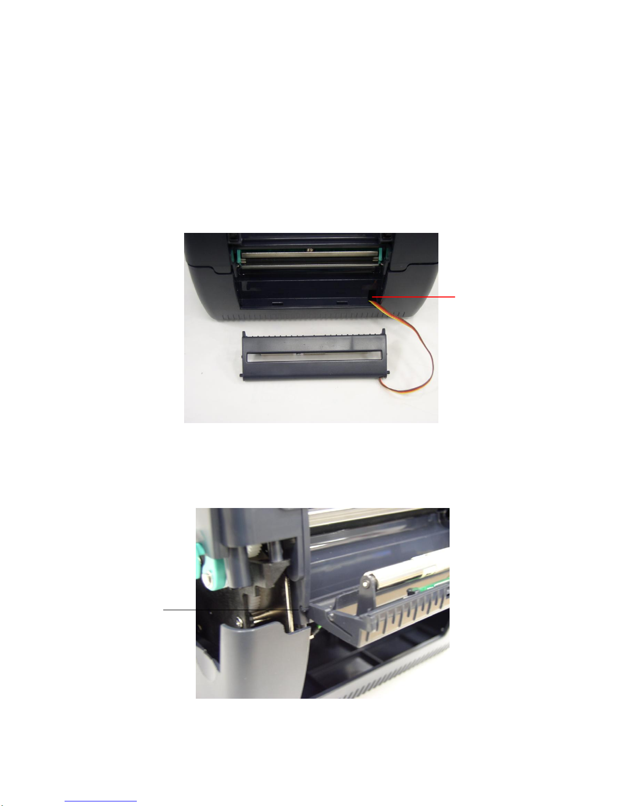
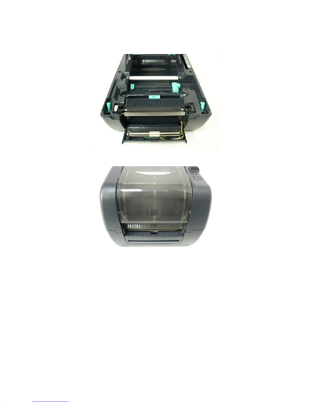
3.14. Install Peel off Module (Option)
1. Open the top cover.
2. Remove two screws for hinge support and one screw for memory card cover in
lower cover.
3. Remove 6 screws on the lower inner cover.
4. Hold the lower cover and lift up the top cover open levers to separate the lower
inner cover and the lower cover. (Please refer to section 3.1 )
5. Connect the harness of peel-off module through the slot of lower inner cover.
6. Lift up the lower inner cover to gently push peel off panel into the two concaves of
lower cover front side.
Note: Must lift up the lower inner cover first, then, the peel-off module could
be installed into the concave of lower inner cover.
Slot
Concave
Page 45
42
7. Connect the harness of peel-off module at JP19 on the main board.
8. Put down the lower inner cover onto lower cover.
9. Push peel off module to lock to the lower inner cover.
10. Reassemble parts in reverse procedures.
Page 46
43
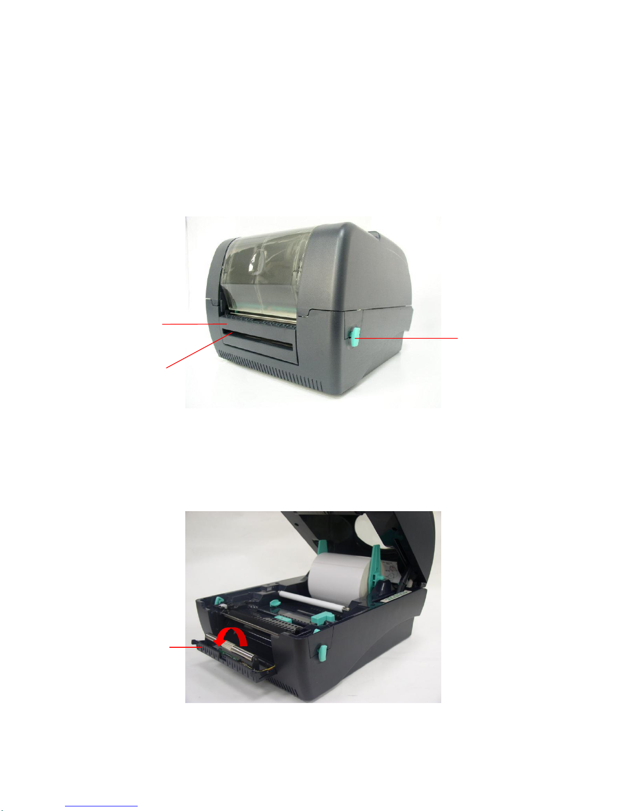
3.15. Loading the Label in Peel-off Mode
Note: Both thermal paper and plain paper apply for peel-off function but
neither PVC nor vynle work at peel-off function.
1. Insert a 1” label spindle into a paper roll.
2. Open the printer top cover by pushing forward the top cover open levers. The top
cover support will hold the printer top cover.
3. Install the paper roll on the paper roll mount.
4. Open the peel-off panel by pulling it out.
Peel-off
panel
Top Cover Open Lever
Backing paper
Opening
Peel-off panel
Page 47
44
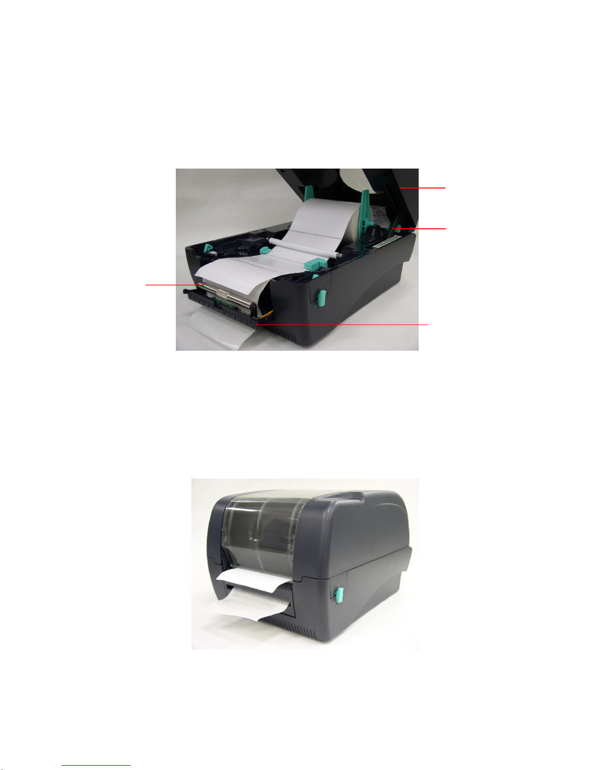
5. Feed the paper, printing side facing up, through the paper guide and pass over the
platen.
6. Lead the paper through the backing paper opening, beneath the roller, and tear off
one piece of the label.
7. Adjust the paper guide by removing left or right to fit the paper width.
Lead the paper through the backing paper opening, beneath the roller
8. Push the peel-off panel back to the printer.
9. Close the top cover by lifting up the top cover support and close the top cover
slowly.
Note: Pull the label outward tightly after closing the top cover.
Complete label installation for peel-off mode
Roller
Top Cover
Peel-off panel
Top Cover Support
Page 48
45
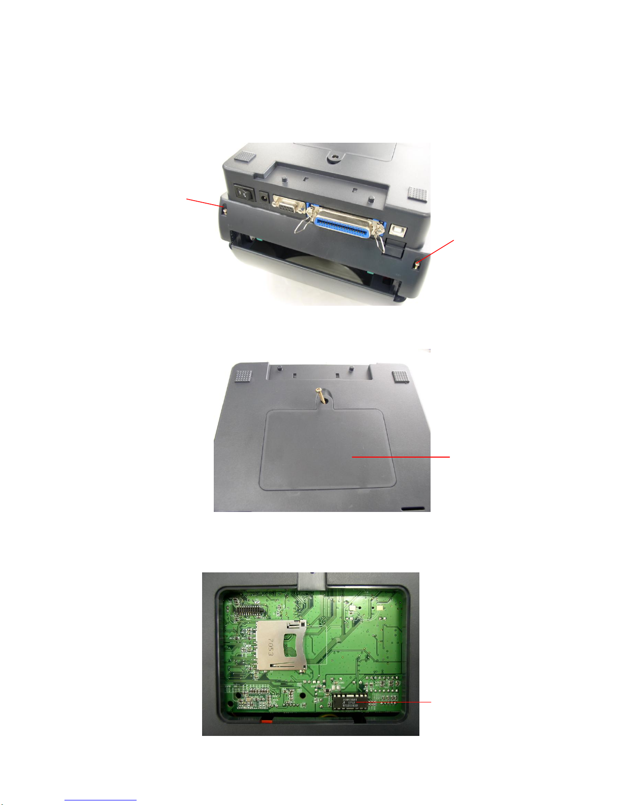
3.16. Install Cutter Module (Option)
1. Upside down the printer to remove two screws of hinge holder in the lower cover.
2. Remove the screw that fixes the memory card cover.
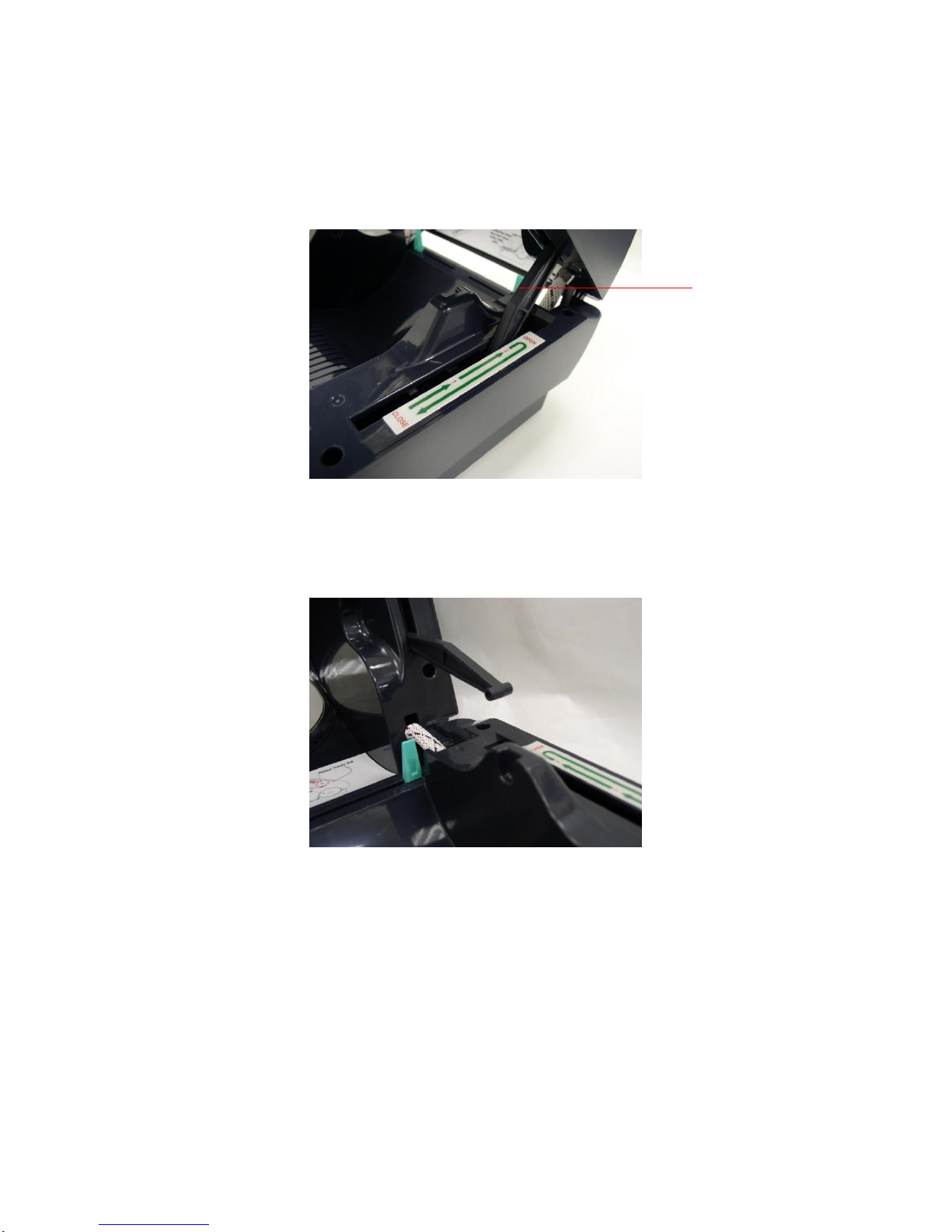
3. Plug in the Cutter Driver IC at U30 socket on the main board.
Cutter Driver IC
Screw of hinge
holder
Screw of hinge
holder
Memory card
cover
Page 49
46
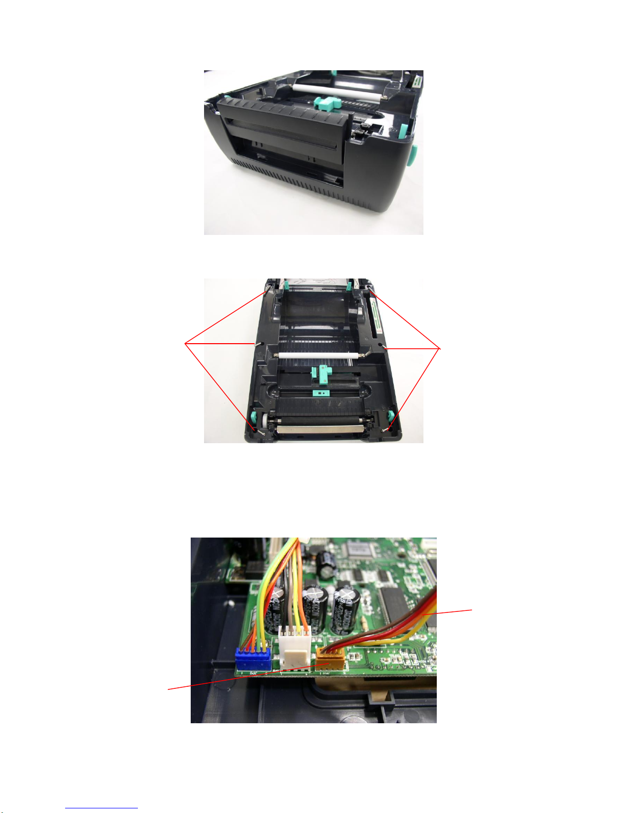
4. Open the printer top cover by pushing the top cover open levers to the paper
outlet direction. The top cover support will hold the printer top cover.
5. Open the top cover to the ultimate open angle. Push the top cover support to the
communication port direction to disconnect the lower inner cover and top cover
support.
6. Pull up the front panel from the lower cover.
Top cover
support
Page 50
47
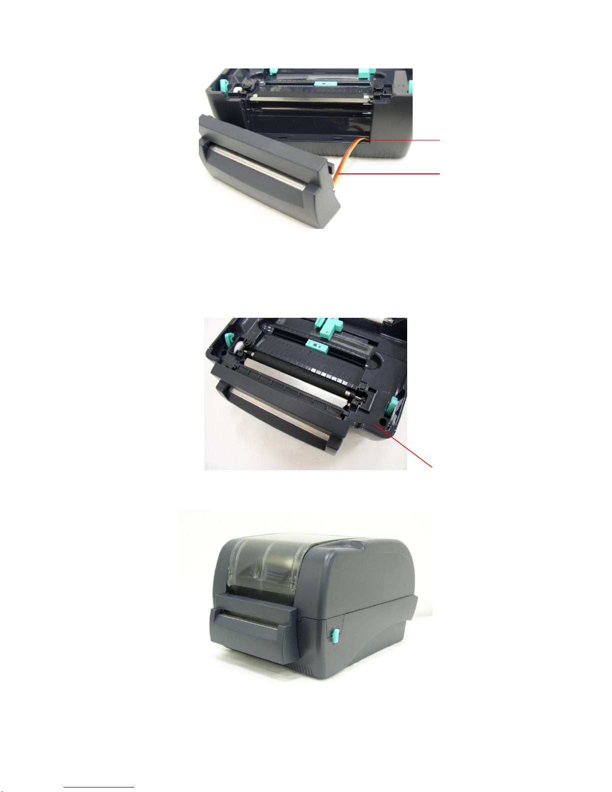
7. Remove the 6 screws in lower inner cover.
8. Lift up the lower inner cover from the Lower Cover.
9. Install the 4 pin connector of the cutter onto JP38 on the main board. Pull the wire
of the 4-pin connector through the slot of lower inner cover front side. Then, put
back the lower inner cover.
Location
JP38
Screws
Screws
Wire of the 4-pin
connector
Page 51
48
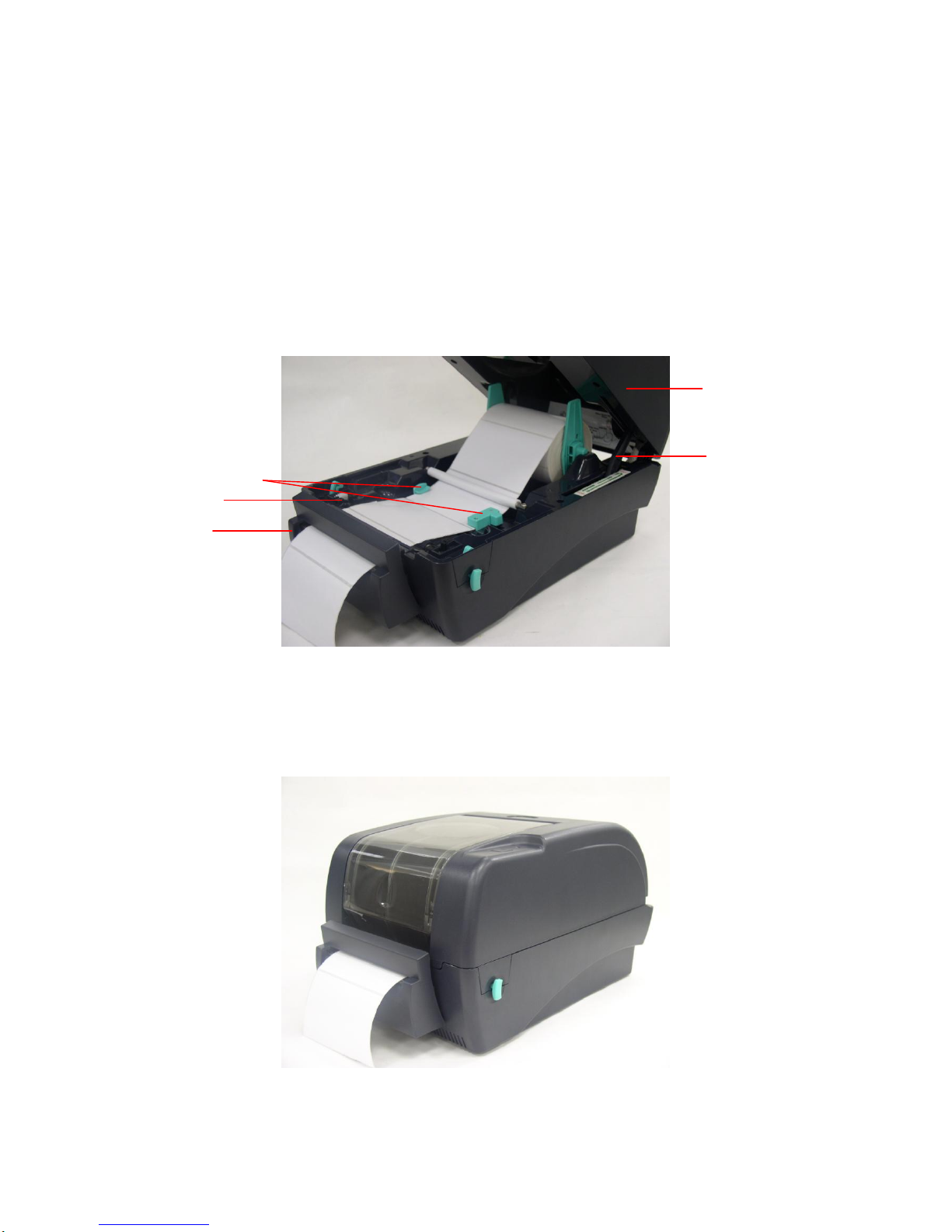
10. Gently push cutter module into the two slots of lower inner cover front side, then
push cutter to lock into the lower inner cover.
11. Assemble the memory card cover.
12. Reassemble parts in reverse procedures.
Cutter wire
Slot
Lower inner
cover
Page 52
49
3.17. Loading Label in Cutter Mode
1. Insert a 1” label spindle into a paper roll.
2. Open the printer top.
3. Install a paper roll on the paper roll mount.
4. Feed the paper, printing side face up, through the paper guide and pass over the
platen.
5. Lead the paper through the cutter paper opening.
6. Adjust the paper guide by removing left or right to fit the paper width.
Label installation in cutter mode
7. Close the top cover by lifting up the top cover support and close the top cover
slowly.
Complete label installation in cutter mode
Top Cover
Paper Guide
Platen
Cutter
Top Cover Support
Page 53
50
3.18. Internal Ethernet Interface Installation (Option)
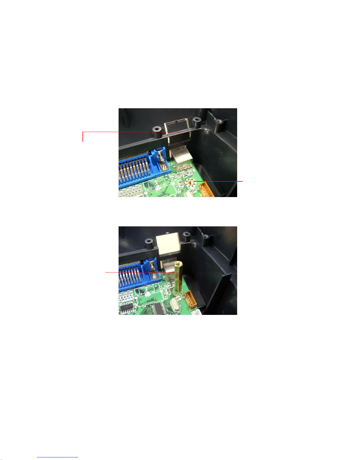
1. Break through the plastic partial tab at the rear side of lower cover to get the RJ45
interface opening.
2. Remove the screw from the main board. Fasten the copper pillar.
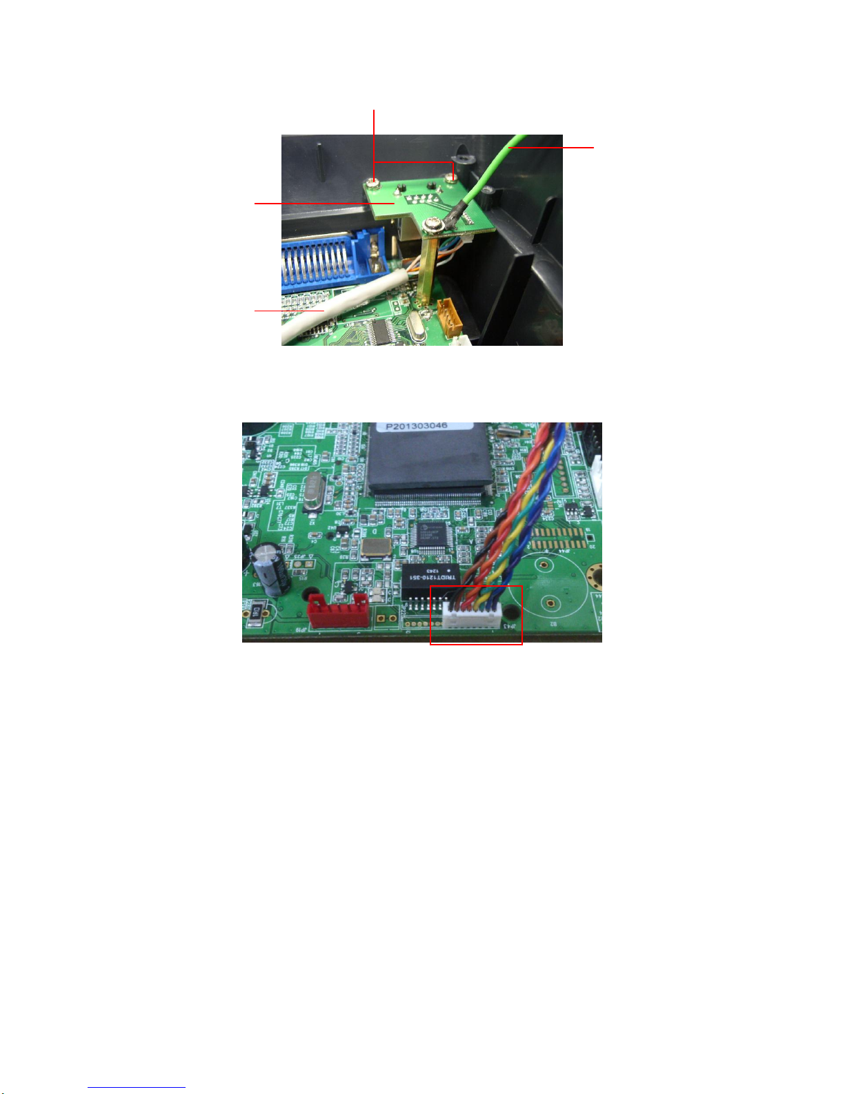
3. Plug the RJ45 cable connector to the RJ45 daughter board connector. Fasten the
RJ45 connector daughter board upon the lower cover and copper pillar. The ground
wire from the mechanism must be screwed on the daughter board at copper pillar.
RJ45 interface opening
Remove the screw
Copper pillar
Page 54
51
4. Plug the 8 pin RJ45 cable to the main board JP43 connector.
Note: This internal Ethernet interface only supports with the main board that has print
server function on board.
Screws
Ground wire
RJ45 / 8 PIN connector
interface cable interface cable
RJ45 connect
daughter board
Page 55

52
4. Power on Utilities
There are six power-on utilities to set up and test printer hardware. These utilities are
activated by pressing FEED button and by turning on the printer power simultaneously.
The utilities are listed as below:
1. Ribbon sensor calibration;Gap/black mark sensor calibration
2. Gap/black mark sensor calibration;Self-test and dump mode
3. Printer initialization
4. Black mark sensor calibration
5. Gap sensor calibration
6. Skip AUTO.BAS
4.1 Ribbon and Gap/Black Mark Sensor Calibration
Gap/black mark sensor sensitivity should be calibrated at the following conditions:
1. A brand new printer
2. Change label stock.
3. Printer initialization.
Please follow the steps below to calibrate the ribbon and gap/black sensor.
1. Turn off the power switch.
2. Hold on the button then turn on the power switch.
3 Release the button when LED becomes red and blinking. (Any red will do during the
5 blinks).
It will calibrate the ribbon sensor and gap/black mark sensor sensitivity.
The LED color will be changed as following order:
Amber red (5 blinks) amber (5 blinks) green (5 blinks)
green/amber (5 blinks) red/amber (5 blinks) solid green
Note:
Please select gap or black mark sensor by GAP or BLINE command prior to
calibrate the sensor.
For more information about GAP and BLINE command, please refer to TSPL2
programming manual.
Page 56

53
4.2 Gap/Black Mark Calibration;Self-test;Dump mode
While calibrate the gap/black mark sensor, printer will measure the label length, print
the internal configuration (self-test) and then enter the dump mode. To calibrate gap or
black mark sensor, depends on the sensor setting in the last print job.
Please follow the steps below to calibrate the sensor.
1.Turn off the power switch.
2. Hold on the button then turn on the power switch.
3. Release the button when LED becomes amber and blinking. (Any amber will do
during the 5 blinks).
The LED color will be changed as following order.
Amber red (5 blinks) amber (5 blinks) green (5 blinks)
green/amber (5 blinks) red/amber (5 blinks) solid green
1. It calibrates the sensor and measures the label length and prints
internal settings then enter the dump mode.
Note:
Please select gap or black mark sensor by Diagnostic Tool or by GAP or BLINE
command prior to calibrate the sensor.
For more information about GAP and BLINE command, please refer to TSPL2
programming manual.
Page 57
54
Self-test
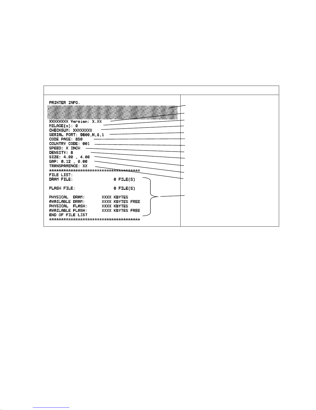
Printer will print the printer configuration after gap/black mark sensor calibration.
Self-test printout can be used to check if there is any dot damage on the heater
element, printer configurations and available memory space.
Self-test printout
Print head check pattern
Model name and F/W version
Printed mileage (meter)
Firmware checksum
Serial port configuration
Code page
Country code
Print speed (inch/sec)
Print darkness
Label size (inch)
Gap distance (inch)
Gap/black mark sensor sensitivity
Numbers of download files
Total & available memory space
Note:
1. The physical flash memory for RoHS compliant version is 2MB Flash and
8MB SDRAM
2. System occupies 960 KB in Flash memory so total flash memory space for
user downloading is 1088 KB
3. System occupies 7936 KB in SDRAM so total SDRAM memory space for user
downloading is 256 KB
Page 58
55
Dump mode
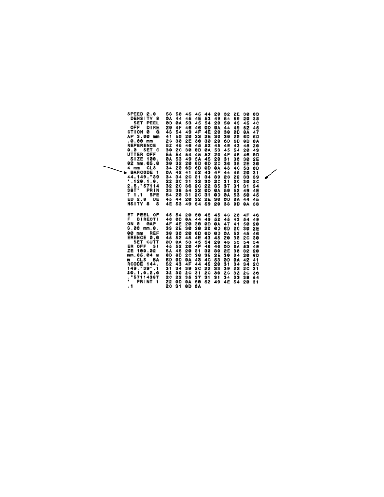
Printer will enter dump mode after printing printer configuration. In the dump mode,
all characters will be printed in 2 columns as following. The left side characters are
received from your system and right side data are the corresponding hexadecimal
value of the characters. It allows users or engineers to verify and debug the program.
Fig. 4 Dump mode printout
Note:
Turn off / on the power to resume printer for normal printing.
ASCII Data
Hex decimal data
related to left
column of ASCII
data
Page 59

56
4.3 Printer Initialization
Printer initialization is used to clear DRAM and restore printer settings to defaults. The
only one exception is ribbon sensitivity, which will note be restored to default.
Printer initialization is activated by the following procedures.
1. Turn off the power switch.
2. Hold on the button then turn on the power switch.
3. Release the button when LED turns green after 5 amber blinks. (Any green will do
during the 5 blinks).
The LED color will be changed as following:
Amber red (5 blinks) amber (5 blinks) green (5 blinks)
green/amber (5 blinks) red/amber (5 blinks) solid green
Printer configuration will be restore to defaults as below after initialization.
Parameter
Default setting
Speed
203 dpi: 127 mm/sec (5 ips)
300 dpi: 76 mm/sec (3 ips)
Density
8
Label Width
4” (101.6 mm)
Label Height
4” (101.6 mm)
Sensor Type
Gap sensor
Gap Setting
0.12” (3.0 mm)
Print Direction
0
Reference Point
0,0 (upper left corner)
Offset
0
Tear Mode
On
Peel off Mode
Off
Cutter Mode
Off
Serial Port Settings
9600 bps, none parity,
8 data bits, 1 stop bit
Code Page
850
Country Code
001
Clear Flash Memory
No
IP Address
DHCP
Note:
Always do gap/black mark sensor calibration after printer initialization.
Page 60

57
4.4 Black Mark Sensor Calibration
Set black mark sensor as media sensor and calibrate the black mark sensor.
Please follow the steps as below.
1. Turn off the power switch.
2. Hold on the button then turn on the power switch.
3. Release the button when LED turns green/amber after 5 green blinks. (Any
green/amber will do during the 5 blinks).
The LED color will be changed as following:
Amber red (5 blinks) amber (5 blinks) green (5 blinks)
green/amber (5 blinks) red/amber (5 blinks) solid green
4.5 Gap Sensor Calibration
Set gap sensor as media sensor and calibrate the gap sensor.
Please follow the steps as below.
1. Turn off the power switch.
2. Hold on the button then turn on the power switch.
3. Release the button when LED turns red/amber after 5 green/amber blinks. (Any
red/amber will do during the 5 blinks).
The LED color will be changed as following:
Amber red (5 blinks) amber (5 blinks) green (5 blinks) green/amber
(5 blinks) red/amber (5 blinks) solid green
4.6 Skip AUTO.BAS
TSPL2 programming language allows user to download an auto execution file to flash
memory. Printer will run the AUTO.BAS program immediately when turning on printer
power. The AUTO.BAS program can be interrupted without running the program by the
power-on utility.
Please follow the procedures below to skip an AUTO.BAS program.
1. Turn off printer power.
2. Press the FEED button and then turn on power.
3. Release the FEED button when LED becomes solid green.
Page 61

58
The LED color will be changed as following:
Amber red (5 blinks) amber (5 blinks) green (5 blinks) green/amber
(5 blinks) red/amber (5 blinks) solid green
2. Printer will be interrupted to run the AUTO.BAS program.
Page 62

59
5. GAP AND BLACK MARK SENSOR SELECTION
Gap Sensor selection
Default setting. No extra action necessary.
If you want to change sensor type from black mark sensor to gap sensor,
please do printer initialization (refer to Initialization section).
Black Mark Sensor
Start Label View XLT+ or Nice Label LE software.
Set label side in the software and select black mark sensor as sensor type.
Install label media with black mark or hole for registration.
Print one label to switch sensor from gap to black mark sensor.
Remember, always do sensor calibration after sensor selection (refer to Gap and
Black Mark Sensor Calibration section).
6. BIOS Update
If printer BIOS update is required, please do the following steps.
Update the BIOS file and reset the printer.
Update File
1. Make sure the printer is at ready status and the LED is solid green.
2. Copy the BIOS file to printer parallel port by the following command at
MS-DOS prompt mode.
C:\>COPY TTP-245P.NEW /B LPT1 <Enter>
3. During BIOS updating process, the LED will blink red and orange alternately.
When BIOS update is completed, printer will reset automatically and LED will
become solid green.
Page 63
60
7. DIAGNOSTIC TOOL
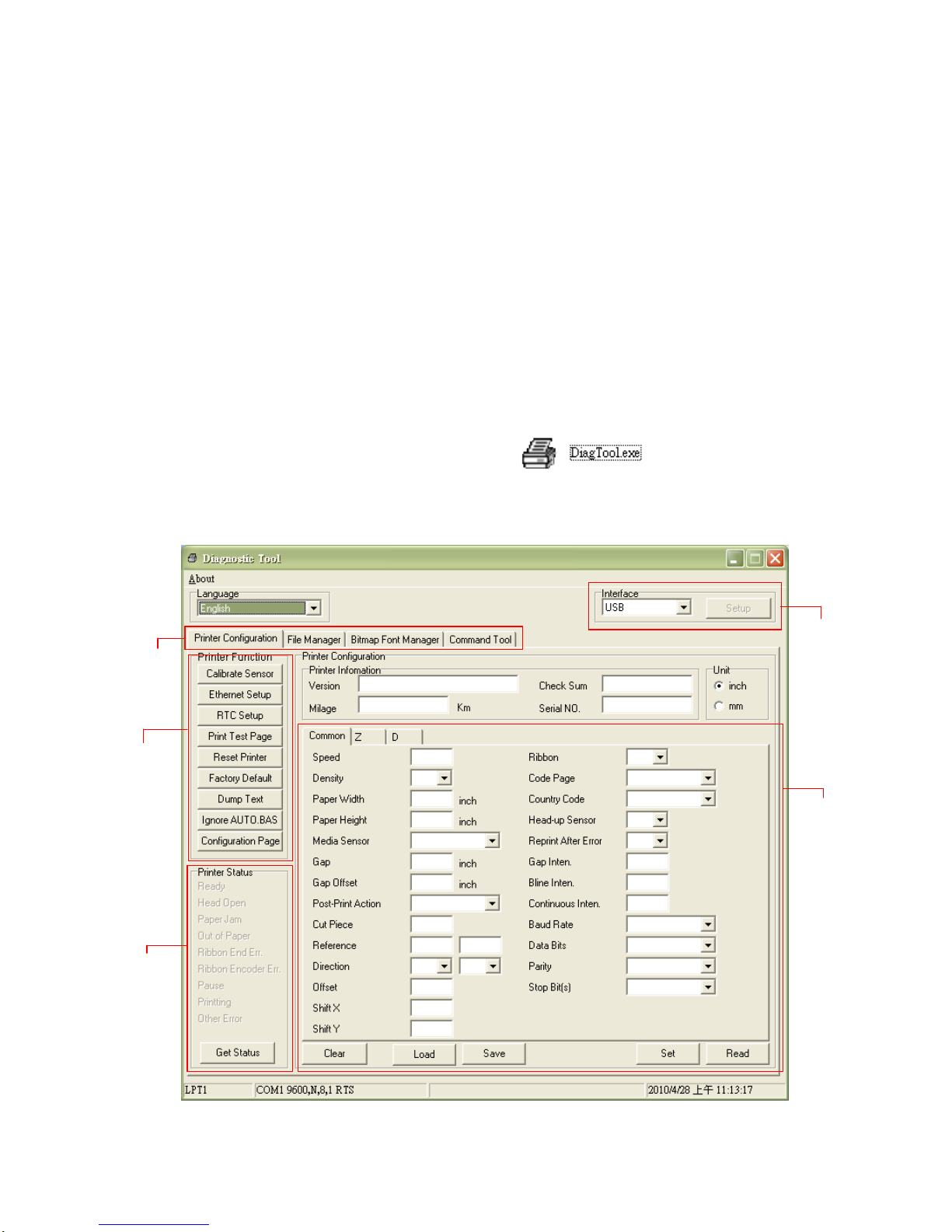
The Diagnostic Utility is a toolbox that allows users to explore the printer’s
settings and status; change printer settings; download graphics, fonts, and
firmware; create printer bitmap fonts; and to send additional commands to the
printer. Using this convenient tool, you can explore the printer status and settings
and troubleshoot the printer.
Note: This utility works with printer firmware V6.00 and later versions.
7.1 Start the Diagnostic Tool
1. Double click on the Diagnostic tool icon to start the software.
2. There are four features (Printer Configuration, File Manager, Bitmap Font
Manager, Command Tool) included in the Diagnostic utility.
Features tab
Printer function
Printer status
Interface
Printer setup
Page 64
61
7.2 Printer Function (Calibrate sensor, Ethernet setup, RTC
setup………)
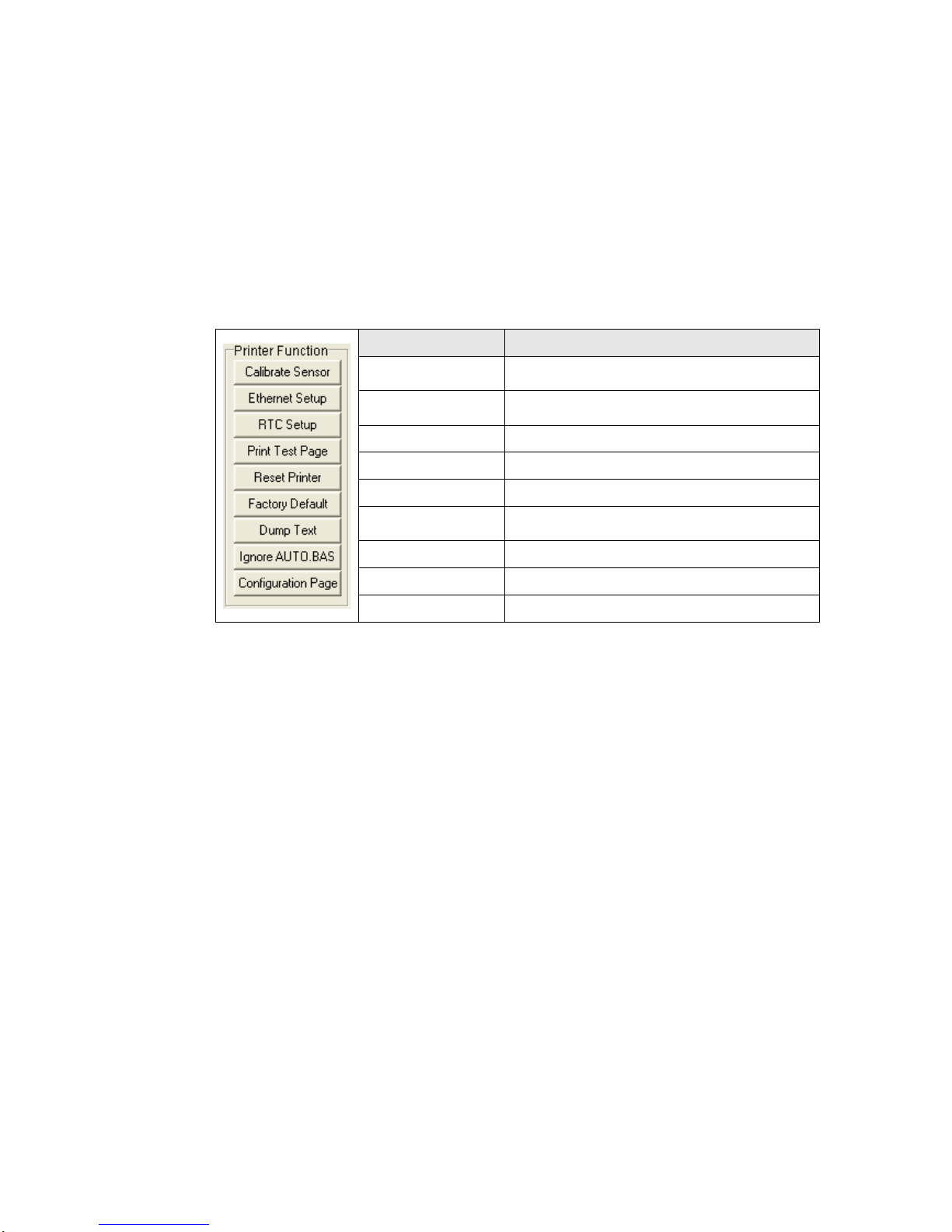
1. Select the PC interface connected with bar code printer.
2. Click the “Function” button to setting.
3. The detail functions in the Printer Function Group are listed as below.
Function
Description
Calibrate Sensor
Calibrate the sensor specified in the Printer
Setup group media sensor field
Ethernet Setup
Setup the IP address, subnet mask, gateway
for the on board Ethernet
RTC Time
Synchronize printer Real Time Clock with PC
Print Test Page
Print a test page
Reset Printer
Reboot printer
Factory Default
Initialize the printer and restore the settings to
factory default.
Dump Text
To activate the printer dump mode.
Ignore AUTO.BAS
Ignore the downloaded AUTO.BAS program
Configuration Page
Print printer configuration
Note:
For more information about Diagnostic Tool, please refer to the diagnostic utility quick
start guide in the CD disk \ Utilities directory.
Page 65

8. TROUBLESHOOTING
This section lists the common problems that you may encounter when operating the
printer.
2. LED does not light on
Turn the power switch on.
Measure if there is 24V DC from the power supply output plug. Change the
power adaptor if 24V DC is not been measured.
Check if U32 (5VDC) and U22 (3.3VDC) of the main board are broken.
Change main board if one of them is broken; Or measure if JP 22 (5VDC) and
the terminal of R316 close to C139 side (3.3VDC) are correct voltage. Change
main board if their voltages are been measured incorrectly.
3. The printer is paused
Press the FEED button to resume printing.
4. The LED is on red and blinking
If the LED is red and blinking, which means that either the label runs out, paper
sensor error, ribbon runs out, ribbon sensor error or ribbon rewind encode sensor
error. We also can use diagnostic tool to get the printer status through COM port or
USB port.
Label runs out (Out of paper):
Load a roll of label and follow the instructions as following and then press the
feed button to resume printing.
1. Insert a 1” label spindle into a paper roll
2. Open the printer’s top cover by releasing the green top cover open levers
located on each side of the printer and lifting the top cover. A top cover
support at the rear of the printer will hold the printer top cover open.
3. Place a roll of paper onto the center of the paper roll mount.
4. Feed the paper, printing side face up, through the Teflon bar and the label
guide and pass over the platen.
5. Adjust the green center-biased label guides in or out so they are slightly
touch the edges of the label backing.
6. To close the printer top cover, lift the cover slightly and pull the top cover
support forward toward the front of the printer. Close the printer top cover
slowly and make sure the cover locks latch securely.
Paper Jam
Select the correct sensor type.
Page 66

63
Calibrate the sensor by clicking the “Calibrate Sensor” button and select
the sensor type for sensor calibration.
Ribbon runs out (out of ribbon):
Load a roll of ribbon and follow the instructions as following and then press
the feed button to resume printing.
1. Push down on the ribbon access window to unlock and open the cover
2. Place a paper core on a ribbon rewind spindle.
3. Mount the ribbon rewind paper core on the front hubs.
4. Install a ribbon on the ribbon supply spindle.
5. Mount the ribbon supply spindle on the rear hubs.
6. Attach the ribbon leader to the ribbon rewind paper core.
7. Rotate the ribbon rewind paper core until the ribbon leader is thoroughly,
firmly encompassed by the black section of the ribbon.
8. Close the ribbon access window.
Ribbon sensor or ribbon rewind encoder error (out of ribbon):
Remove the ribbon, close the ribbon mechanism then turn off/on the printer
power. The printer will be switched to thermal direct mode automatically.
If the printer LED is still on red blink, please check the following:
A. Is a paper core installed on the ribbon rewind spindle?
B. Is ribbon installed correct along the ribbon path?
C. Is the ribbon too transparent?
D. Is the rib of the ribbon spindle is broken?
E. Is the ribbon gear broken or worn?
F. Turn off printer power. Rewind the ribbon spindle by hand. Does the
spindle rewind smoothly by hand? If the ribbon spindle doesn’t rewind
smoothly, please replace the ribbon mechanism.
G. Is the DC motor broken?
H. Is the ribbon end sensor broken?
I. Is the DC motor encoder sensor broken?
Measure the current of pin2 of JP37. When sensor detects the gap of
encoder, it is 5V DC; otherwise it should be 0V DC.
Check if there is any black lubricant oil filled between gaps, which may
cause error.
J. Check the DC motor driver IC (U29) on the main board. If it can function all
right, please replace the main board.
Paper sensor error
Please check the following items:
A. Is label installed correctly? Please refer to previous 3. The LED is on with red
Page 67

64
blinking – Label runs out to load a roll of label and then press the FEED button
to resume printing.
B. Is there any label stuck on the label sensor? Is there any pre-printed logo on
the label? Please refer to 4.3 Printer Initialization to reset the system.
If the pre-printed logo or text influences the auto gap calibration function, please
calibrate the gap sensor with proper sensitivity setting by try and error method.
Example:
C:\>COPY CON LPT1 <Enter>
SET GAP 1 <Ctrl> <Z>
Main board, gap sensor or black sensor failure.
If you confirm the main board is good, Please change the gap sensor receiver
first, because the receiver sensor failure rate is higher then the transmitter
sensor.
5. The printer setting runs error.
Printer setting runs error:
Refer to 4.3 Initialization to reset the system.
6. Continuous feeding labels
The printer setting may go wrong. Please do “Printer Initialization” and “Gap
and Black Mark Sensor Calibration”. (Refer to 4.2 and 4.3).
7. No print on the label
Is the label or ribbon loaded correctly? Refer to No, 3 Label runs out and
Ribbon runs out to load the paper or to load the ribbon.
Does the ribbon run out?
Is the thermal head connector connected?
Is the thermal head broken? Check it by printer self-test printout.
Is main PCB U14, U15, Q1 or Q2 broken?
8. Printer does not print.
Printed by enclosed BarTender
This may be driver conflict problem. Please remove all the drivers in the
printer folder and then re-install the driver for your printer.
Printed by printer command (other error).
This problem is caused by incorrect syntax commands. This printer will ignore
incorrect syntax commands. Please set the printer to the dump mode and
make sure the printed command is identical to the commands sent from the
Page 68

65
application software.
The printer serial port setting is not correspondent to the PC’s setting
Please do the configuration by the following commands.
C:\>COPY CON LPT1 <Enter>
SET COM1 96,N,8,1 <Enter>
<Ctrl>Z<Enter>
C:\>
9. Poor print quality
The dust or glue from label may stick onto the print head. Wipe the thermal
print head by the soft cloth soaked with Ethanol.
Adjust the print density setting.
Ribbon and paper media are not compatible.
If this problem happens after changing a new print head module, adjust the
print head’s heater line position by re-assembling print head module.
10. Stepping motor does not feed label
Is stepping motor function abnormal?.
Check if U18, and U19 (3717 driver IC) of main board are broken?
11. LED keeps at solid amber.
Is switching power broken?
Is main board broken? Please replace a new main board.
Try to update the firmware on line. Press the FEED and power on the printer
at same time. Press the FEED again while the first green LED is on. Finally,
transmit the firmware program to the printer from PC.
12. Cutter functions abnormally.
Cutter is not activated (other error)
At first, check if cutter is broken or the main PCB is damaged. If it still has problem
after changing a new cutter, perhaps the U30 (driver IC), U28 IC or U34 on the
main board was broken. Otherwise, check if the pin 28 of U2 (CPU) is good.
13. Black mark can’t be detected properly (out of paper or paper jam)
Please check if the position of the black mark on label is correspondent with
black mark sensor.
Is the width of black mark on label too thin to be detected? The
recommended black mark width is wider than 12 mm.
Page 69
66
9. MAINTENANCE
This session presents the clean tools and methods to maintain your printer.
1. Please use one of following material to clean the printer.
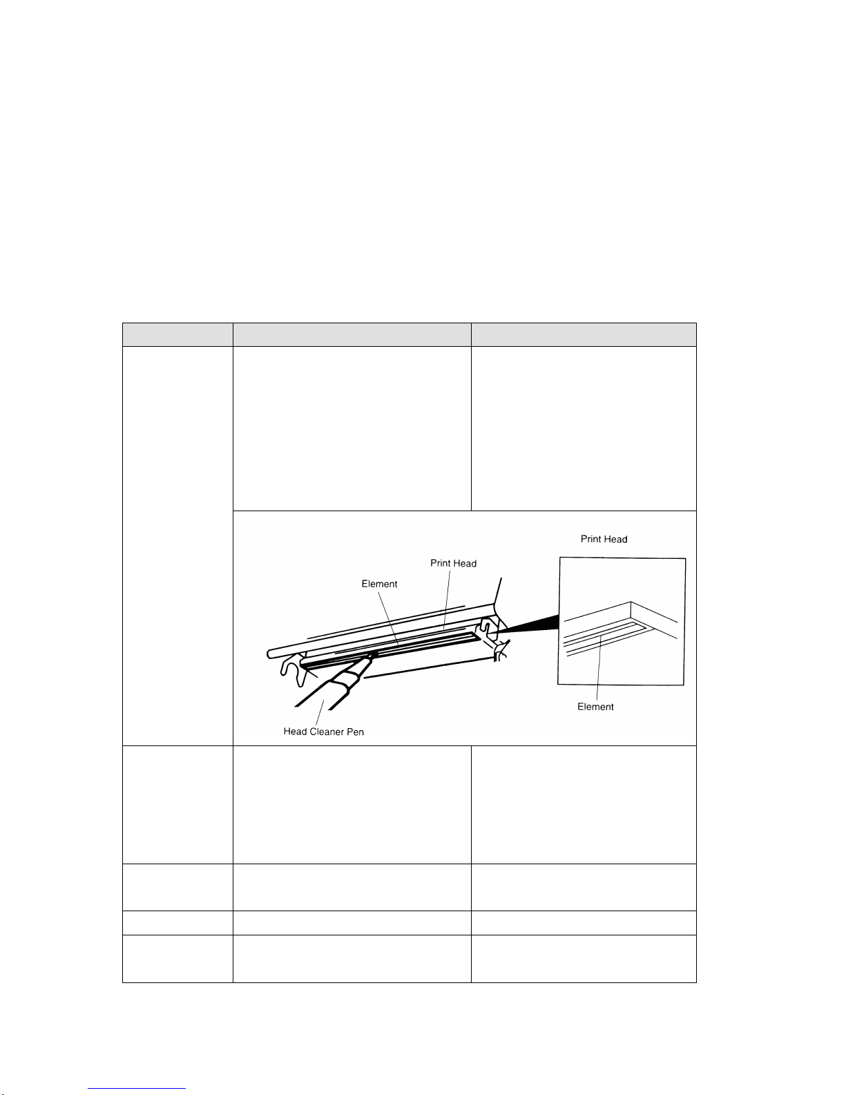
Cotton swab (Head cleaner pen)
Lint-free cloth
Vacuum / Blower brush
100% ethanol
1. The cleaning process is described as following
Printer Part
Method
Interval
Print Head
1. Always turn off the printer
before cleaning the print head.
2. Allow the print head to cool for
a minimum of one minute.
3. Use a cotton swab (Head
cleaner pen) and 100% ethanol
to clean the print head surface.
Clean the print head when
changing a new label roll
Platen Roller
1. Turn the power off.
2. Rotate the platen roller and
wipe it thoroughly with 100%
ethanol and a cotton swab, or
lint-free cloth.
Clean the platen roller when
changing a new label roll
Tear Bar/Peel
Bar
Use the lint-free cloth with 100%
ethanol to wipe it.
As needed
Sensor
Compressed air or vacuum
Monthly
Exterior
Wipe it with water-dampened
cloth
As needed
Page 70

67
Interior
Brush or vacuum
As needed
Note:
Do not touch printer head by hand. If you touch it careless, please use ethanol to
clean it.
Please use 100% Ethenol. DO NOT use medical alcohol, which may damage the
printer head.
Regularly clean the print head and supply sensors once change a new ribbon to
keep printer performance and extend printer life.
Page 71

68
UPDATE HISTORY
Date
Content
Editor
2008/4/17
Add the part no. for Switzerland type power cord
Camille
2008/4/22
Revise the description for 98-0250184-00LF (Main
board ass’y with internal print server kit)
Camille
2008/5/14
Revise the black mark sensor assembly part no.
Camille
2008/5/27
Revise the print head harness part no. from
70-52B2604-11LF to 72-0250008-00LF
Camille
2008/6/16
1. Revise the hinge holder part no.
2. Revise the TPH plastic bracket part no.
Camille
2008/7/11
Remove the parts list section
Camille
2008/12/12
Add connector JP6 description
Camille
2009/3/16
Modify section 3.13 (Recommended SD card
specification)
Camille
2009/10/6
Revise section 2.1
Camille
2010/7/1
*Add TTP-247/TTP-345 printer
*Add the section 1.2.2
*Update the section 7
Camille
2011/1/17
Modify section 2.1 and 3.4
Camille
2011/1/25
Modify TSC address
Camille
2011/4/8
Modify section 2.2
Camille
2013/3/13
Modify section 2.1
Camille
2014/8/1
Add section 3.18
Camille
Page 72

Corporate Headquarters Li Ze Plant
9F., No.95, Minquan Rd., Xindian Dist., No.35, Sec. 2, Ligong 1st Rd., Wujie Township,
New Taipei City 23141, Taiwan (R.O.C.) Yilan County 26841, Taiwan (R.O.C.)
TEL: +886-2-2218-6789 TEL: +886-3-990-6677
FAX: +886-2-2218-5678 FAX: +886-3-990-5577
Web site: www.tscprinters.com
E-mail: [email protected]
TSC Auto ID Technology Co., Ltd.
 Loading...