

Page 1
TTP-2610MT/ TTP-368MT Series
SERVICE
MANUAL
THERMAL TRANSFER / DIRECT THERMAL
BAR CODE PRINTER
Page 2

i
TABLE OF CONTENT
1. FUNDAMENTAL OF THE SYSTEM .......................................................................... 3
1.1. Overview ............................................................................................................................................... 3
2. ELECTRONICS .......................................................................................................... 7
2.1 Summary of Board Connectors ............................................................................................................. 7
2.2 Pin Configuration ................................................................................................................................. 12
3. MECHANISM ........................................................................................................... 14
3.1 Remove Covers ................................................................................................................................... 14
3.2 Replacing the LCD Panel Module ....................................................................................................... 16
3.3 Replacing the Power Supply Unit ........................................................................................................ 18
3.4 Replacing Multi-interface Board .......................................................................................................... 19
3.5 Replacing the Main Board ................................................................................................................... 20
3.6 Replacing the Platen Roller Assembly ................................................................................................ 21
3.7 Replacing the Stepping Motor ............................................................................................................. 22
3.8 Replacing the Print head ASS'Y .......................................................................................................... 23
3.9 Replacing the Gap and Black-mark Sensor Module ........................................................................... 25
3.10 Replacing the DC Motor Module ....................................................................................................... 26
3.11 Cutter Module Installation (Option) .................................................................................................... 27
3.12 Replacing the Cutter Driver IC Board (Option) .................................................................................. 29
3.13 Peel-off kit Installation ........................................................................................................................ 30
3.14 Slot-in Wifi Housing Installation (Option) ........................................................................................... 40
4. TROUBLESHOOTING ............................................................................................. 41
4.1 Common Problems .............................................................................................................................. 41
4.2 Print Head Pressure Adjustment Knob ................................................................................................ 45
4.3 Mechanism Fine Adjustment to Avoid Ribbon Wrinkles ...................................................................... 46
4.4 Z-axis Mechanism Adjustment Knob ................................................................................................... 48
5. MAINTENANCE ....................................................................................................... 50
UPDATE HISTORY ...................................................................................................... 52
Page 3

Page 4
3
1. FUNDAMENTAL OF THE SYSTEM
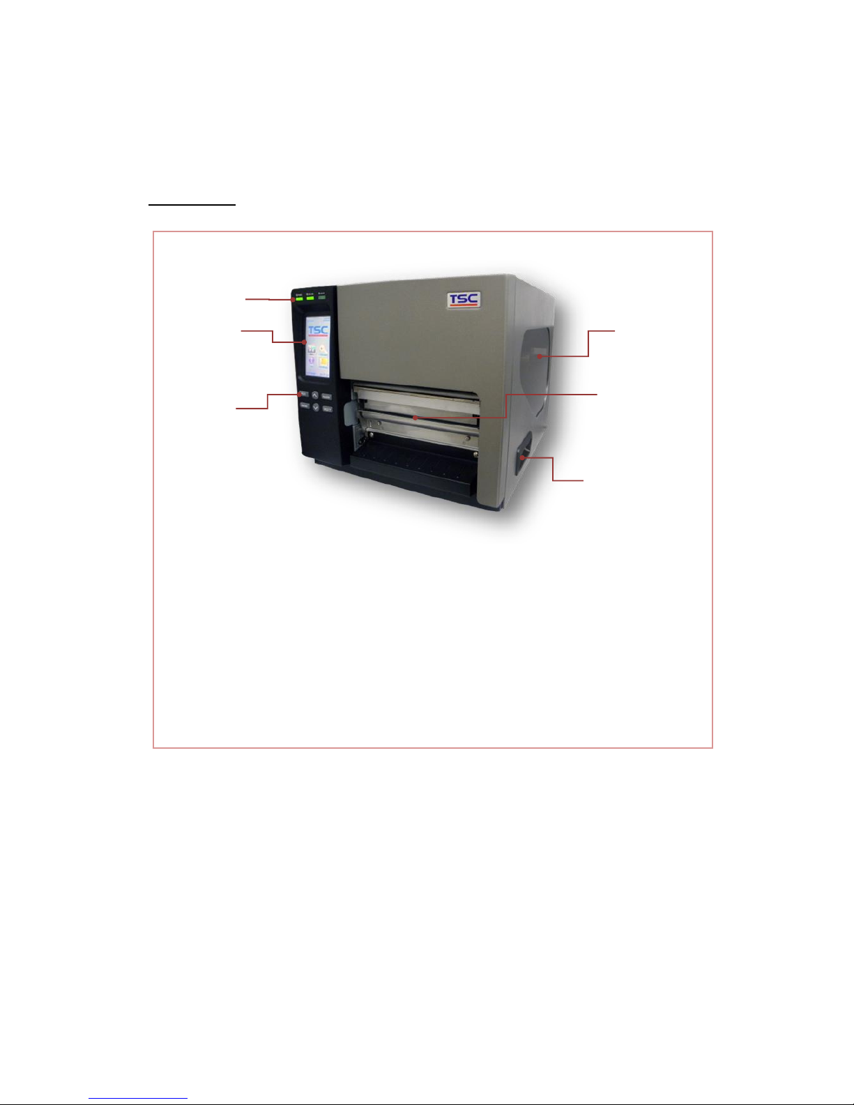
1.1. Overview
Front View
1. LED indicators
2. Touch screen
3. Operation buttons
4. Media viewer
5. Paper exit chute
6. Printer right side cover opener
2
1
3
4
5
6
Page 5
4
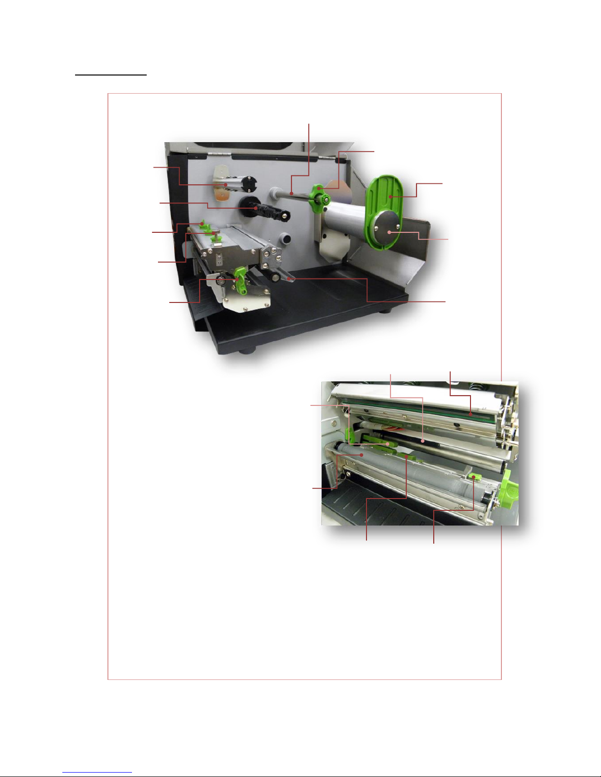
Interior View
1. Ribbon rewind spindle
2. Ribbon supply spindle
3. Print head pressure adjustment knobs
4. Z axis mechanism adjustment knob
5. Print head release lever
6. Media guide bar
7. Rear label guide
8. Label roll guard
9. Label supply spindle
10. Damper
11. Print head
12. Ribbon sensor
13. Gap sensor
14. Platen roller
15. Black mark sensor
16. Front label guide
2
1
3
4
13
7 5 8
9
10
11
12
6
14
15
16
Page 6
5
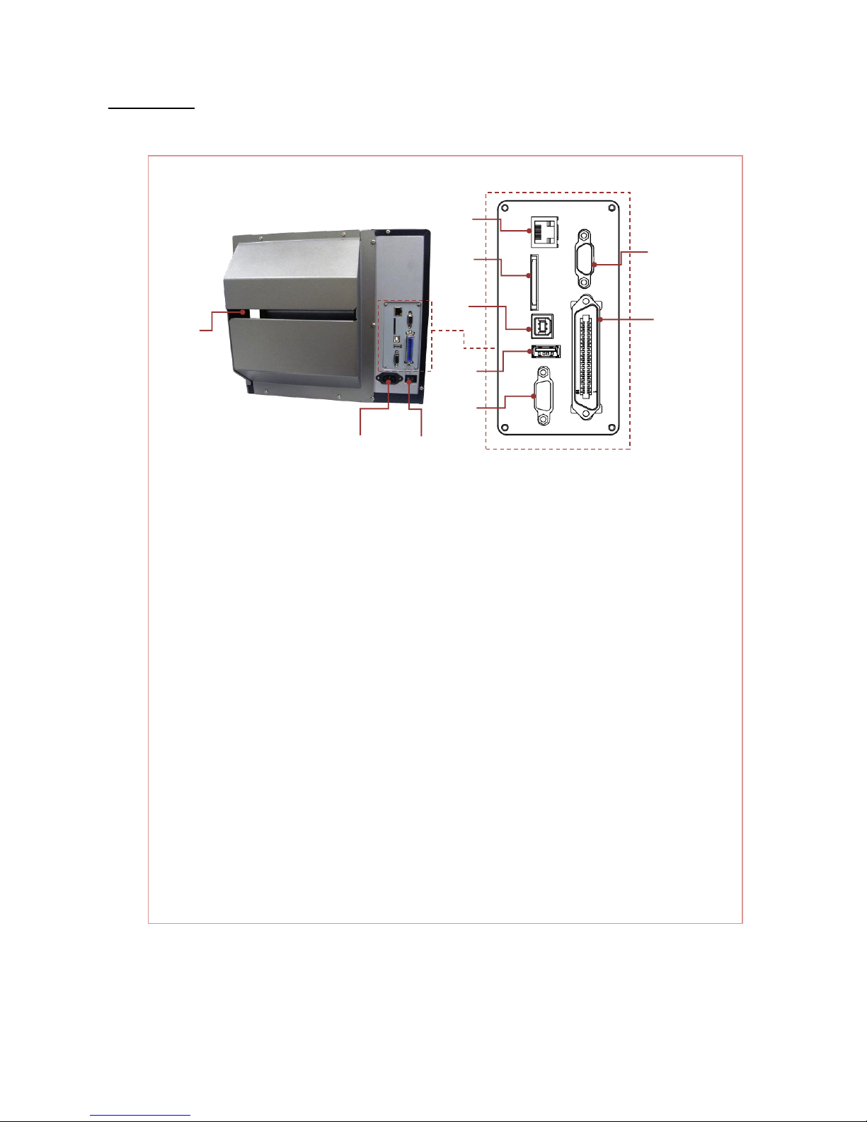
Rear View
1. External label entrance chute
2. Power cord socket
3. Power switch
4. Ethernet interface
5. * SD card socket
6. USB interface
7. USB host
8. RS-232C interface
9. GPIO interface (Option)
10. Centronics interface
Note:
The interface picture here is for reference only. Please refer to the product specification
for the interfaces availability.
1
3
2
4
7
6
5
8
9
10
Page 7

6
* Recommended SD card specification
Type
SD card spec
SD card capacity
Approved SD card manufacturer
SDHC
V2.0 Class 4
2G
Transcend
V3.0 Class 10
32G
Kingston
V3.0 Class 10
16G
Kingston
V2.0 Class 4
8G
Scandisk
V3.0 Class 10
32G
Scandisk
Micro SD
V2.0 Class 4
4G
Transcend
V2.0 Class 4
8G
Transcend
V3.0 Class 10 UHS-I
16G
Transcend
V3.0 Class 10 UHS-I
32G
Transcend
V3.0 Class 10
16G
Kingston
V2.0 Class 4
16G
Scandisk
V3.0 Class 10 UHS-I
16G
Scandisk
- The DOS FAT file system is supported for the SD card.
- Folders/files stored in the SD card should be in the 8.3 filename format.
- The miniSD/microSD card to SD card slot adapter is required.
Page 8
7
2. ELECTRONICS
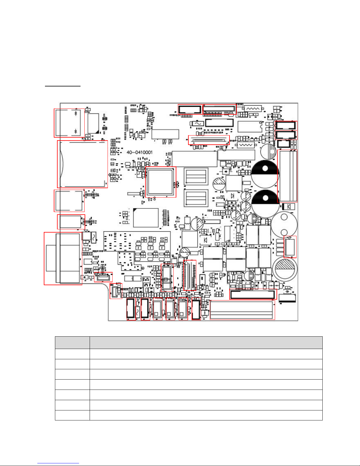
2.1 Summary of Board Connectors
Main board
Connector
Description
1
Ethernet RJ-45 connector
2
SD card slot
3
USB device connector
4
USB host connector
5
RS-232C connector
6
Microprocessor
7
GPIO connector
2
3
5
10 6 12
11
20
19
16
17 4 1
7
18
21
22
23
24
25
14
15 9 8
13
Page 9
8
8
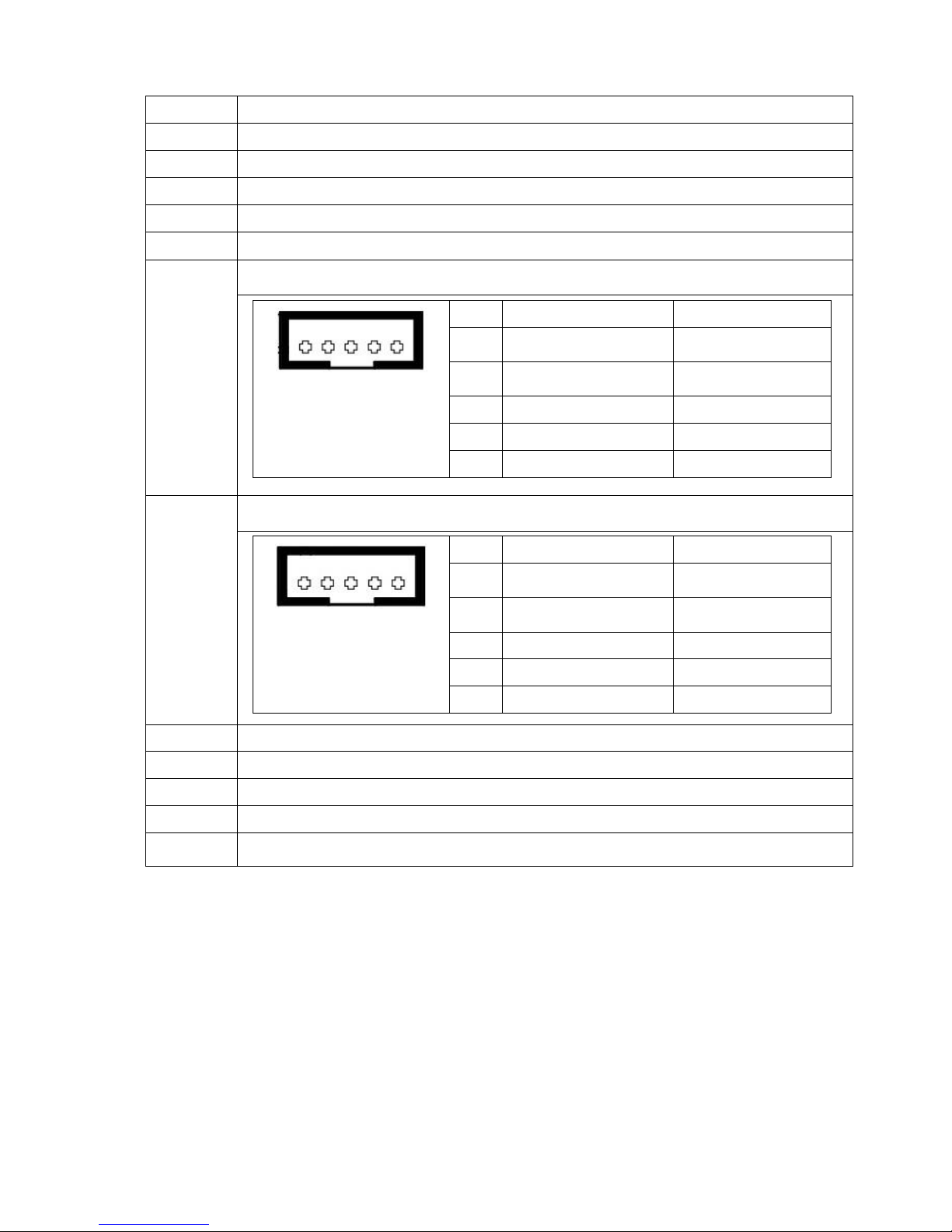
Centronics port FPC connector
9
TFT LCD panel FPC connector
10
KEY & LED connector
11
USB host internal connector (Reserve)
12
I2C internal connector (Reserve)
13
RFID module connector (4” 6pin / 6” or 8” 4pin)
14
Ribbon recover sensor connector (For 6” 8” used only) (Blue)
Pin
Description
Voltage
1
Ribbon encoder sensor
emitter power pin
4.0~4.15V
2
Ribbon encoder sensor
receiver
A/D: 0~3.3V
3
GND
0V 4 DC motor signal pin
5
DC motor signal pin
15
Ribbon supply sensor connector (For 6” 8” used only) (Red)
Pin
Description
Voltage
1
Ribbon encoder sensor
emitter power pin
4.0~4.15V
2
Ribbon encoder sensor
receiver
A/D: 0~3.3V
3
GND
0V 4 DC motor signal pin
5 DC motor signal pin
16
Power supply output (24V DC) connector
17
Stepping motor connector
18
Print head data connector
19
Print head power connector
20
Cutter/peel-off sensor connector
5 4 3 2 1
5 4 3 2 1
Page 10
9
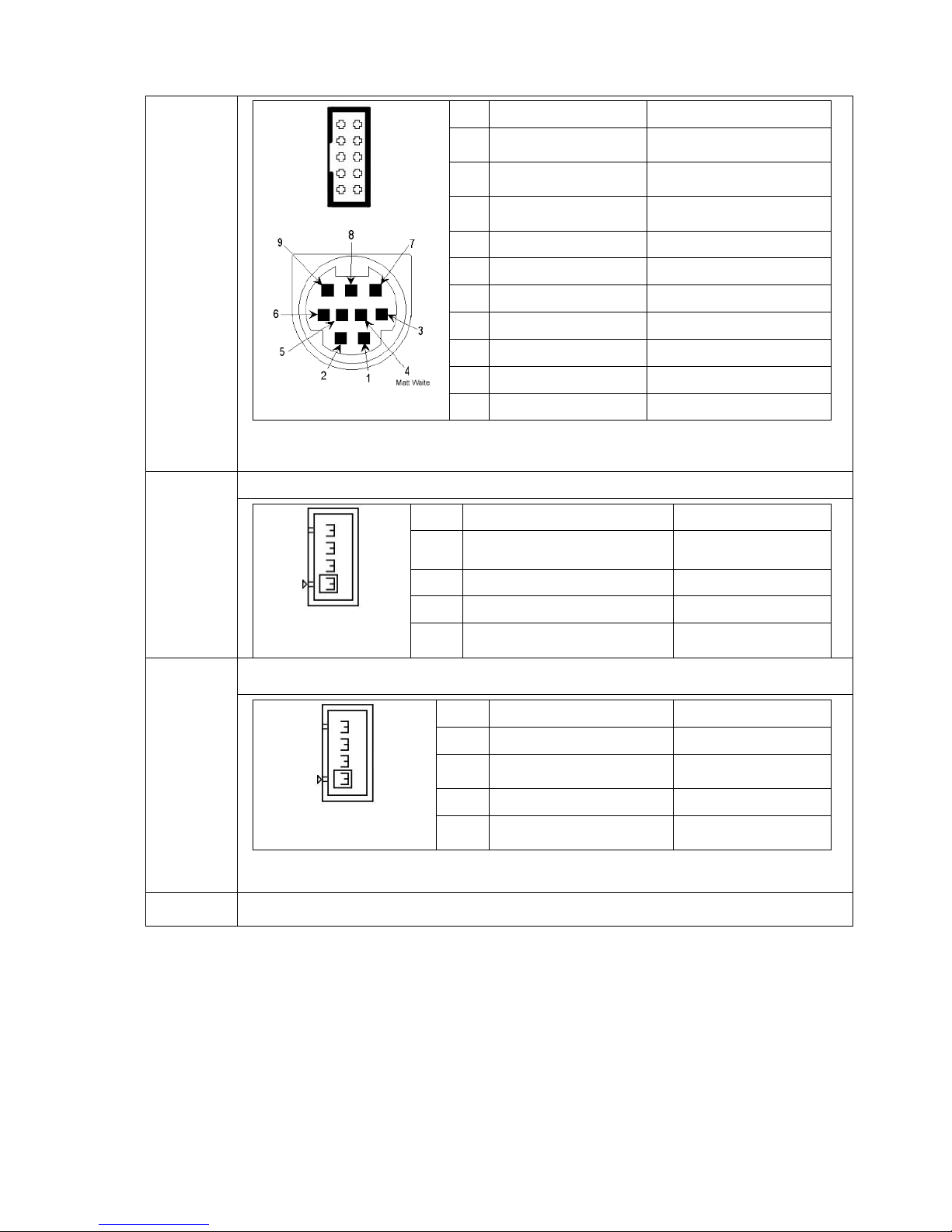
Note:
9 Pin Mini Din for cutter/peel-off module connector
Pin
Description
Voltage
1
Cutter enable
0V: Cutter work
5V: Cutter stop
2
Cutter direction
0V: Cutter positive cut
5V: Cutter negative cut
3
Cutter position sensor
switch
0V: Cutter stop
3.3V: Cutter work
4
Peel sensor receiver
A/D: 0~3.3V
5
N/A
N/A
6
Logic power
5V 7 GND
0V 8 Cutter power
24V
9
I2C SCL signal
10
I2C SDA signal
21
Head open sensor connector
Pin
Description
Voltage
1
Head open sensor emitter
power pin
1.2~1.4V
2
GND
0V 3 Logic power
3.3V
4
Head open sensor receiver
0V: Head close
3.3V: Head open
22
Ribbon sensor connector
Pin
Description
Voltage
1
Ribbon sensor receiver
A/D: 0~3.3V
2
Ribbon sensor emitter
power pin
5V
3
GND
0V
4
Ribbon sensor emitter
4.0~4.1V: Emitter on
4.3~4.4V: Emitter off
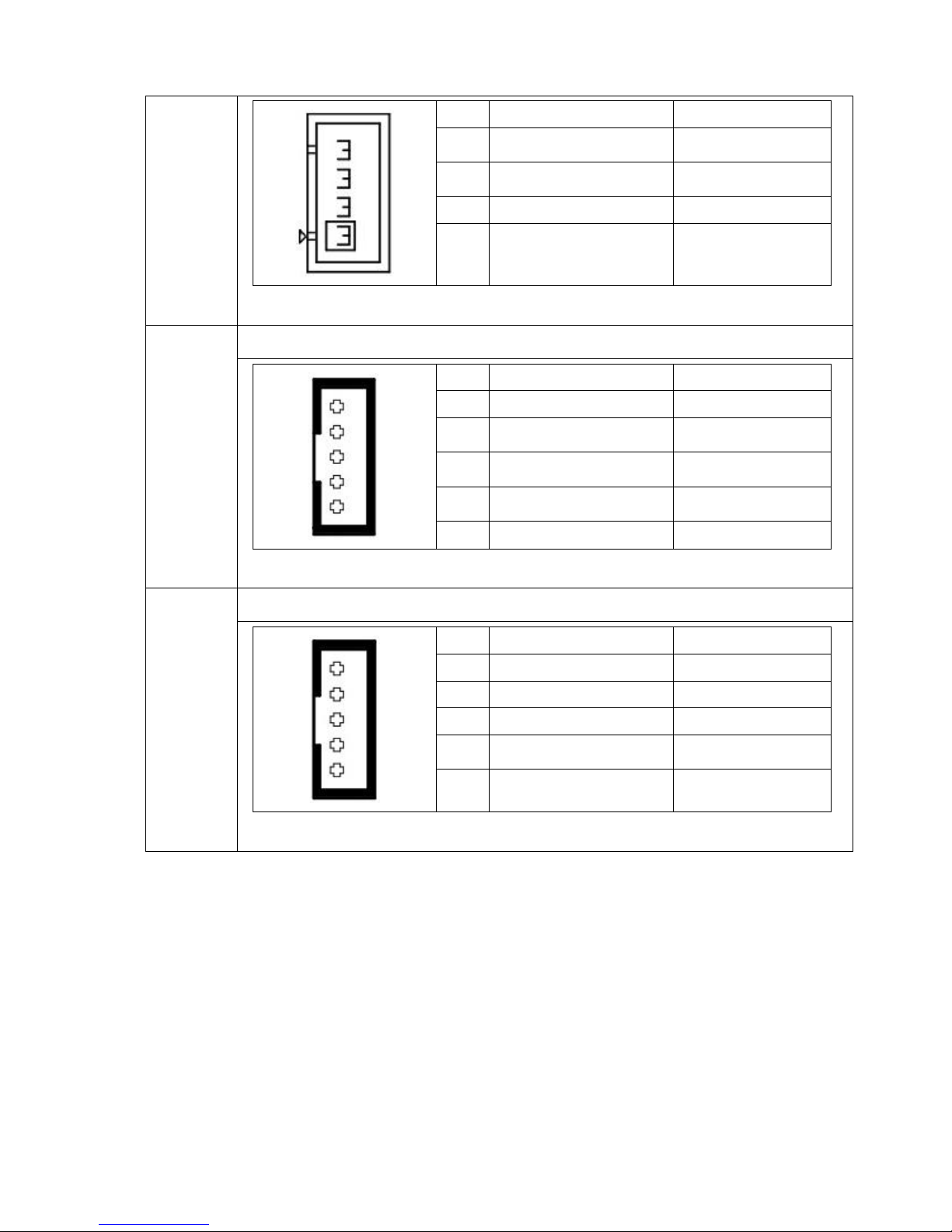
23
Black mark sensor connector (For 6” 8” used only)
4
3
2
1
4
3
2
1
1 2
3 4
5 6
7 8
9 10
Page 11
10
Pin
Description
Voltage
1
Black mark sensor
receiver
A/D: 0~3.3V
2
Black mark sensor emitter
power pin
5V
3
GND
0V
4
Black mark sensor emitter
4.0~4.1V: Emitter on
4.3~4.4V: Emitter off
24
Gap sensor connector
Pin
Description
Voltage
1
Power
5V
2
Gap sensor emitter
4.0~4.1V: Emitter on
4.3~4.4V: Emitter off
3
Black mark sensor emitter
4.0~4.1V: Emitter on
4.3~4.4V: Emitter off
4
Gap and black mark
sensor receiver
A/D: 0~3.3V
5
GND
0V
25
Rewind connector
Pin
Description
Voltage
1
Power
24V 2 Cutter direction signal
3 Cutter enable signal
4
Cutter position sensor
switch signal
5
GND
0V
5
4
3
2
1
5
4
3
2
1
4
3
2
1
Page 12
11
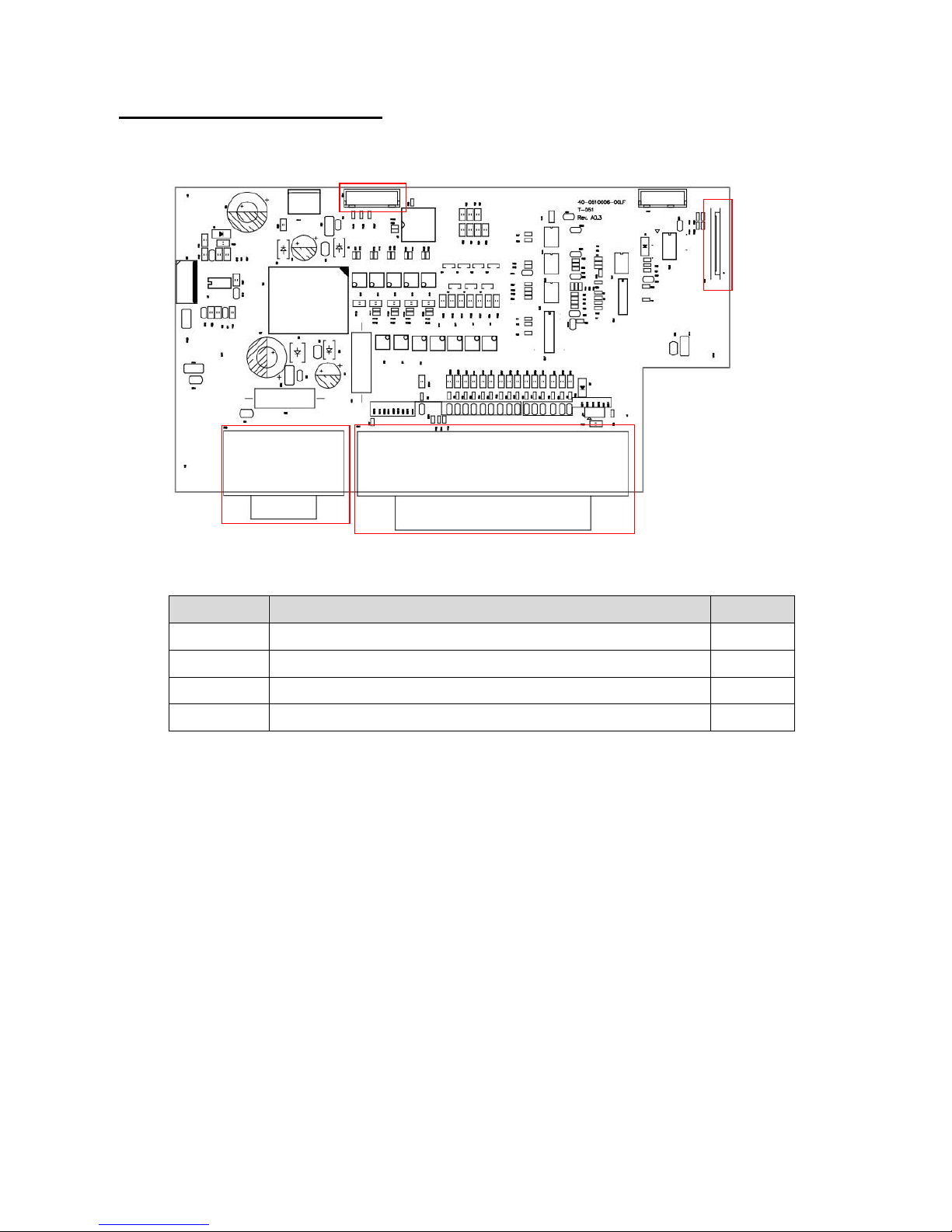
GPIO with multi-interface board
Connector
Description
Remark
1
GPIO connector
2
GPIO power and control signal connector
3
Centronics port connector
4
Centronics port FPC connector
2 1 4
3
Page 13
12
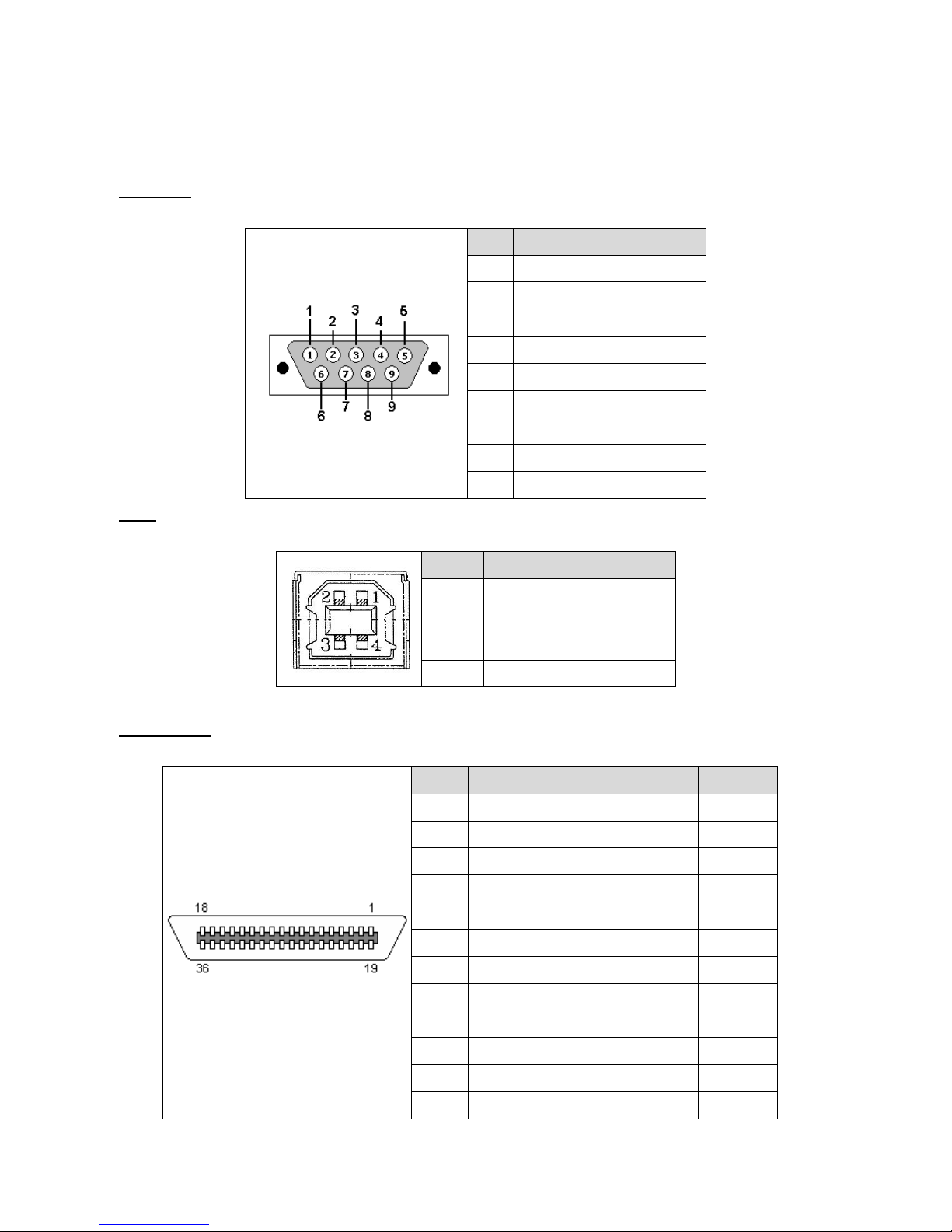
2.2 Pin Configuration
RS-232C
PIN
CONFIGURATION
1
+5 V
2
TXD
3
RXD
4
CTS
5
GND
6
RTS
7
N/C
8
RTS
9
N/C
USB
PIN
CONFIGURATION
1
N/C 2 D- 3 D+
4
GND
Centronics
Pin
SPP Mode
Nibble
In/Out
1
Strobe
N/A
In
2-9
Data 0-7
N/A
In
10
Ack
N/A
Out
11
Busy
N/A
Out
12
Paper Out / End
N/A
Out
13
Select
N/A
Out
14
Ground
N/A
GND
15
No Defined
N/A
N/A
16-17
Ground
N/A
GND
18
No Defined
N/A
N/A
19-30
Ground
N/A
GND
31
No Defined
N/A
N/A
Page 14
13
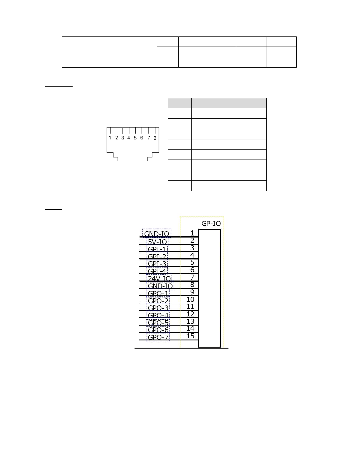
32
Error / Fault
N/A
Out
33-35
Ground
N/A
GND
36
No Defined
N/A
N/A
Ethernet
PIN
CONFIGURATION
1
Tx+ 2 Tx- 3 Rx+
4
N/C
5
N/C 6 Rx- 7 N/C 8 N/C
GPIO
Page 15
14
3. MECHANISM
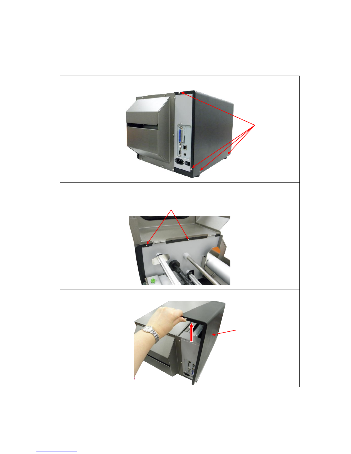
3.1 Remove Covers
1. Remove 4 screws from printer.
2. Open printer right side cover and remove 2 screws then close the cover.
3. Remove the electronics cover.
Screws
Screws
Electronics
cover
Page 16
15
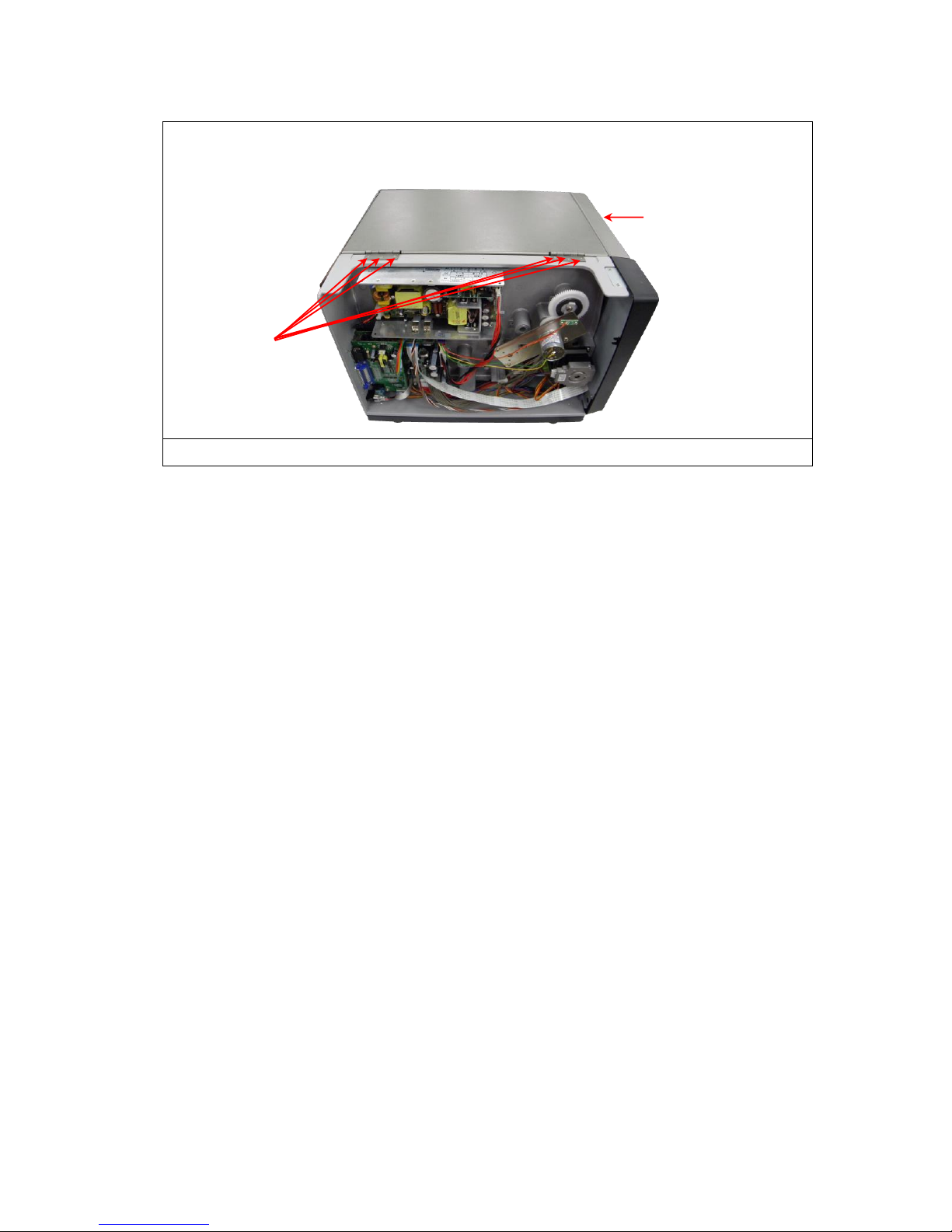
4. Remove 6 screws from each hinge. Be careful the right side cover may fall out
from the printer. Take out the right side cover from the printer.
5. Reassemble the parts in the reverse procedures.
Screws
Right side cover
Page 17
16
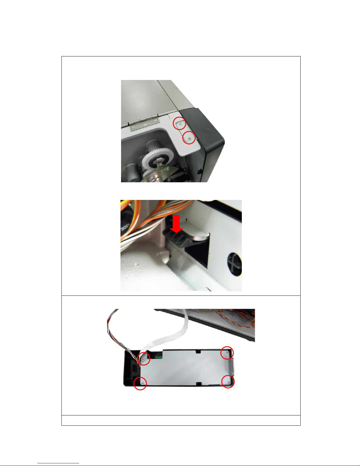
3.2 Replacing the LCD Panel Module
1. Refer to section 3.1 to remove the electronics cover.
2. Remove 2 screws on the module bracket.
3. Push down the tab to remove the LCD panel module.
4. Remove 4 screws to remove the module bracket.
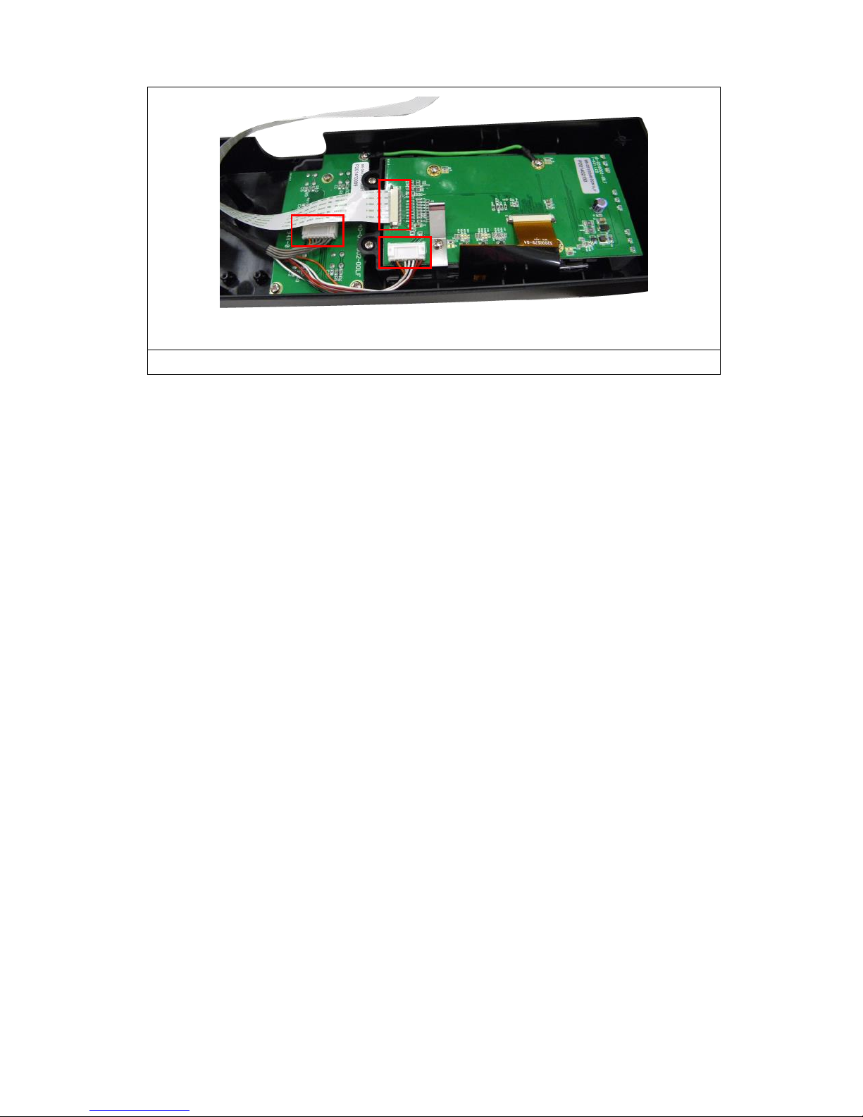
5. Disconnect 3 harnesses to replace the LCD panel module.
PUSH
Page 18
17
6. Reassemble the parts in the reverse procedures.
Page 19
18
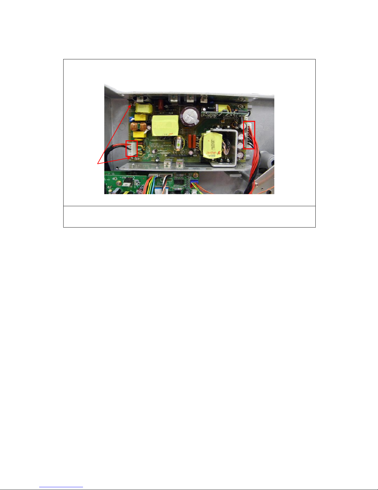
3.3 Replacing the Power Supply Unit
1. Refer to section 3.1 to remove the electronics cover.
2. Disconnect 2 connectors, and remove 2 screws on the power supply unit.
3. Replace the power supply unit.
4. Reassemble the parts in the reverse procedures.
Screws
Page 20
19
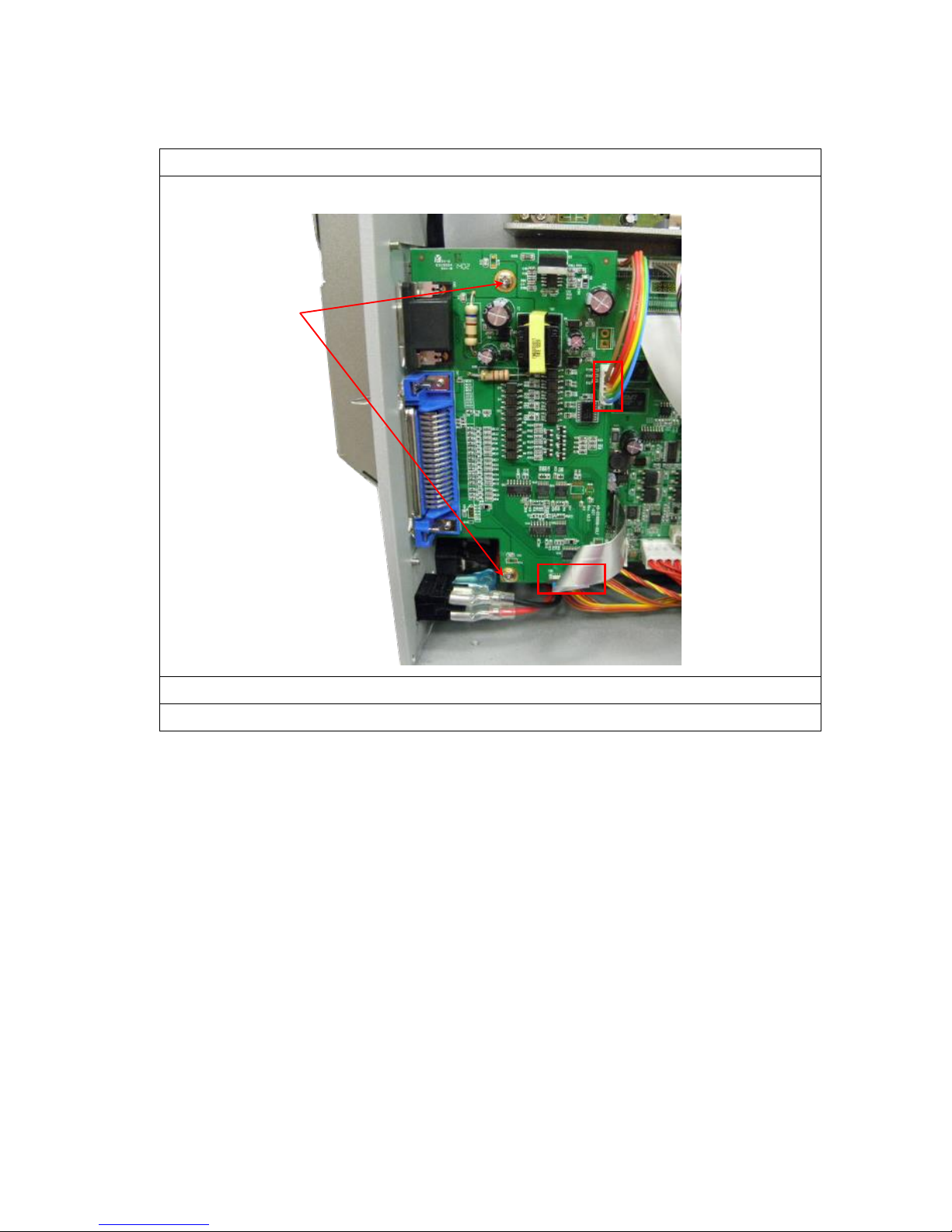
3.4 Replacing Multi-interface Board
1. Refer to section 3.1 to remove the electronics cover.
2. Remove 2 screws from multi-interface board. Disconnect 2 connectors.
3. Replace the multi-interface board.
4. Reassemble the parts in the reverse procedures.
Screws
Page 21
20
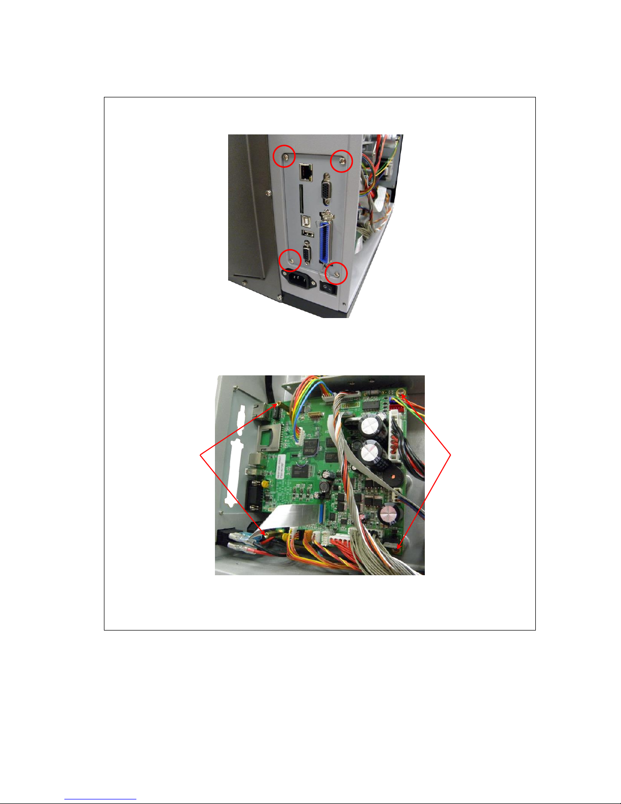
3.5 Replacing the Main Board
1. Refer to section 3.1 to remove electronics cover.
2. Remove 4 screws to take off the interface plate.
2. Refer to section 3.4 to remove multi-interface board.
3. Disconnect all connectors to replace the main board. Remove 2 copper pillars
and 2 screws.
4. Replace the main board.
5. Reassemble the parts in the reverse procedures.
Copper pillars
Screws
Page 22
21
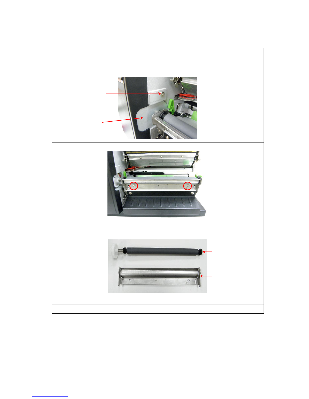
3.6 Replacing the Platen Roller Assembly
1. Open printer right side cover.
2. Disengage print head lift lever.
3. Remove the 1 screw to remove gear cover.
4. Remove 2 screws from the platen holder.
5. Take out the platen holder, platen roller assembly and replace a new platen
roller assembly.
6. Reassemble the parts in the reverse procedures.
Platen roller
assembly
Platen
holder
Screws
Gear cover
Page 23
22
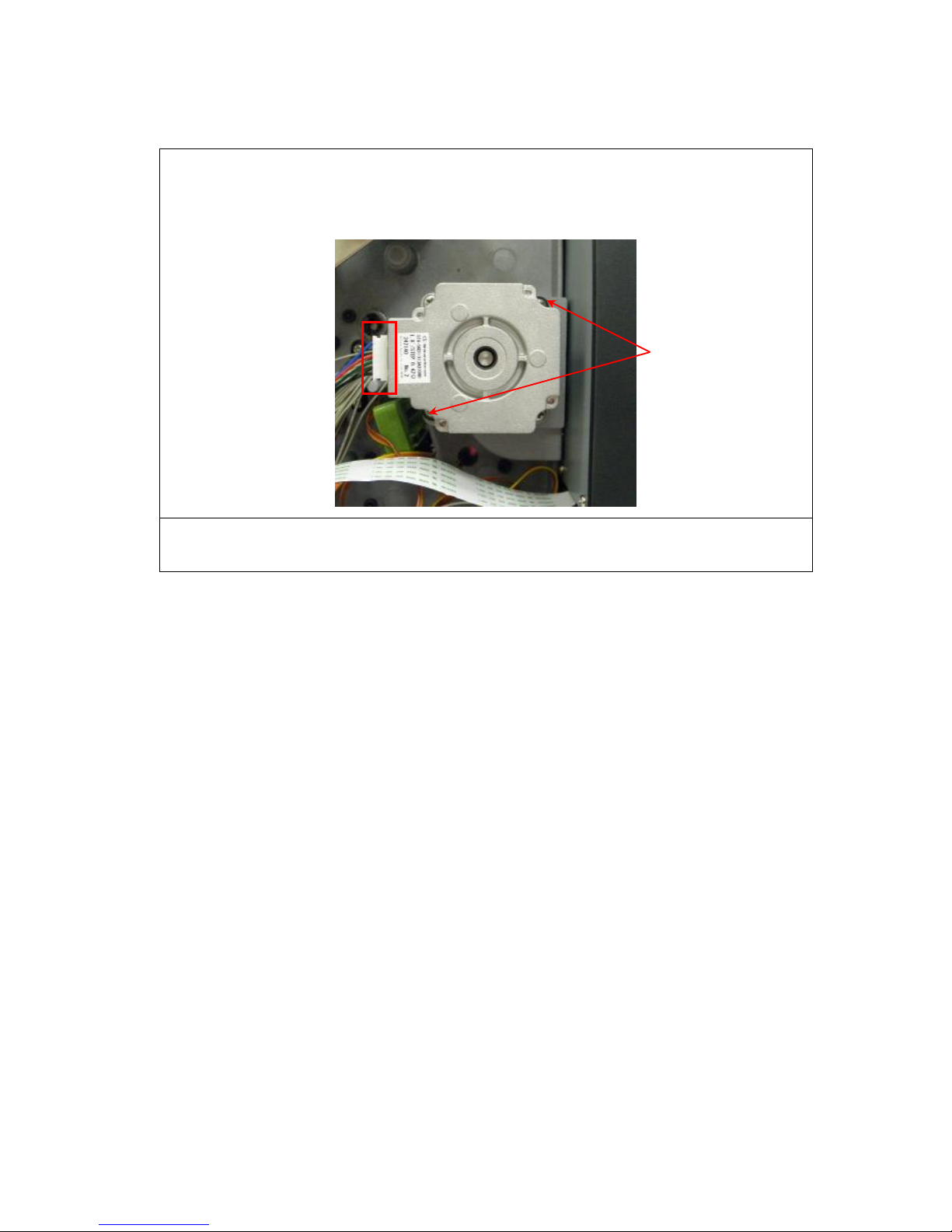
3.7 Replacing the Stepping Motor
1. Refer to section 3.1 to remove the electronics cover.
2. Disconnect the stepping motor connector. Remove 2 screws on the stepping
motor.
3. Replace the stepping motor.
4. Reassemble the parts in the reverse procedures.
Screws
Page 24
23
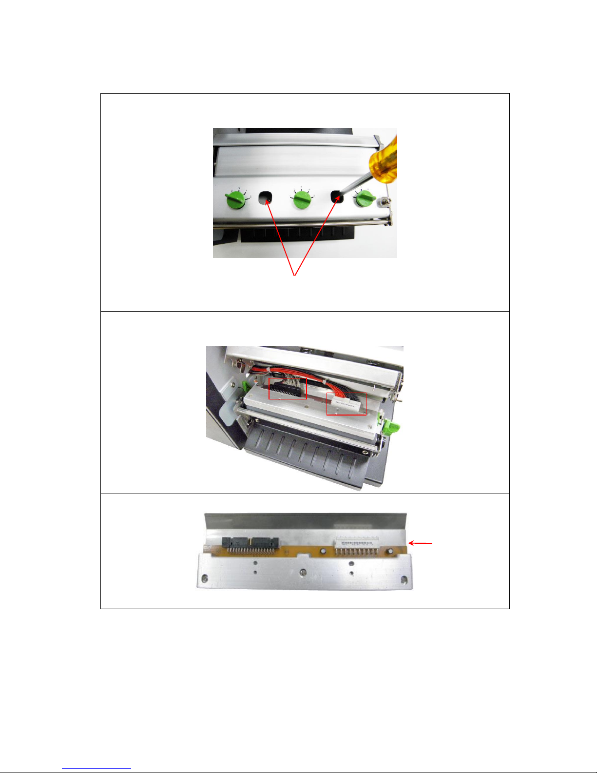
3.8 Replacing the Print head ASS'Y
1. Open the printer right side cover.
2. Remove 2 screws from the mechanism.
3. Disengage print head release lever.
4. Carefully disconnect 2 connectors from the print head ASS'Y.
5. Replace the print head ASS'Y.
Screws
Print head
ASS'Y
Page 25
24
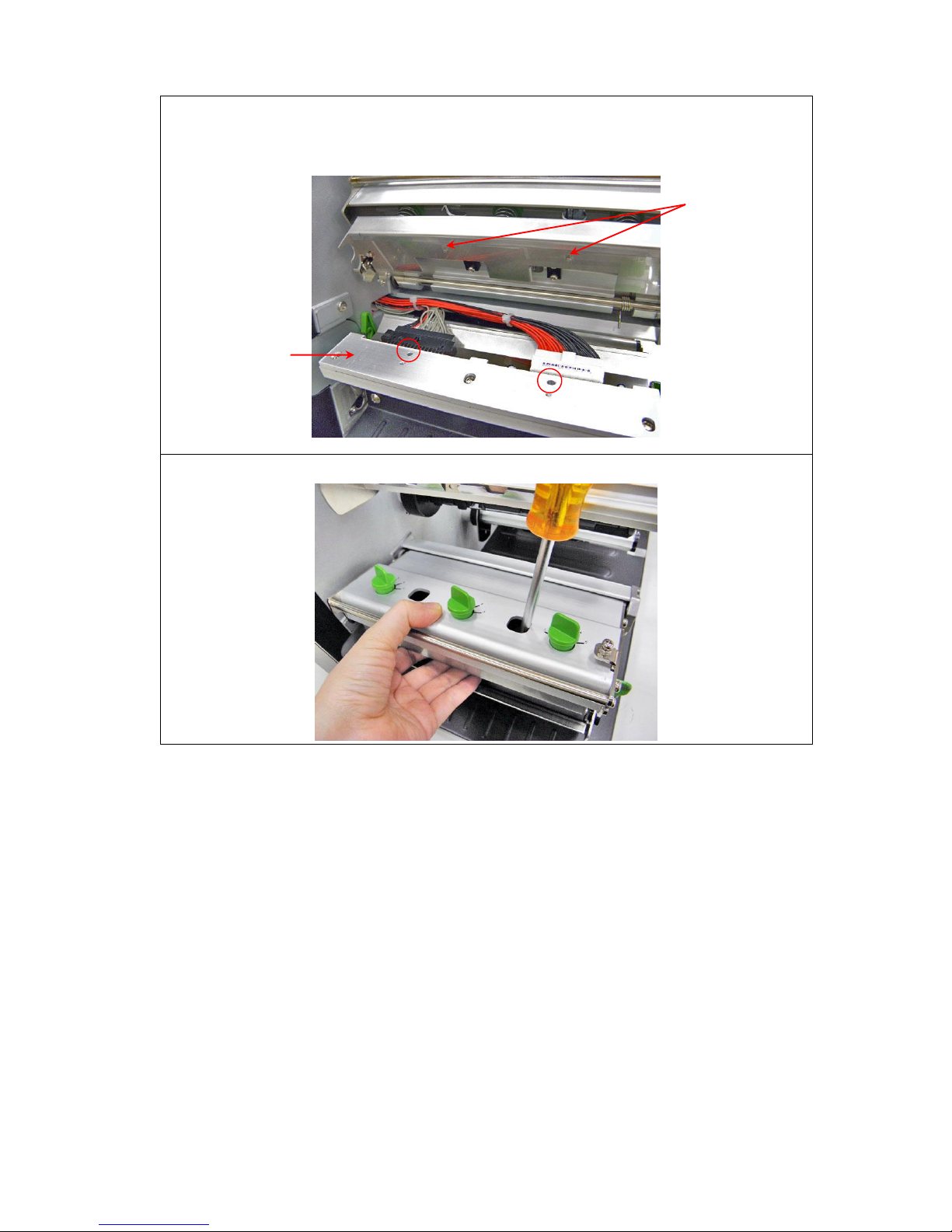
6. Connect the print head cable and carefully slide assembly into the print
mechanism. The holes of print head assembly must align and then insert the
tenons of print mechanism.
7. Reassemble the parts in the reverse procedures.
Print head
ASS'Y
Tenons
Page 26
25
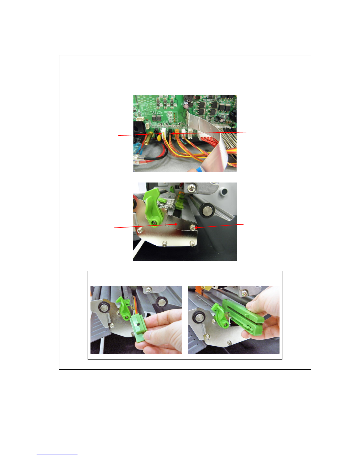
3.9 Replacing the Gap and Black-mark Sensor Module
1. Open the printer right side cover.
2. Disengage print head release lever.
3. Refer to section 3.1 and 3.4 to remove electronics cover and multi-interface board.
4. Disconnect the gap and black-mark sensor connectors from the main board.
5. Remove 1 screw to take off the sensor cover from print head mechanism.
6. Replace the sensor module.
Black-mark sensor module
Gap sensor module
7. Reassemble the parts in the reverse procedures.
Black-mark sensor
module connector
Gap sensor
module connector
Screws
Sensor
cover
Page 27
26
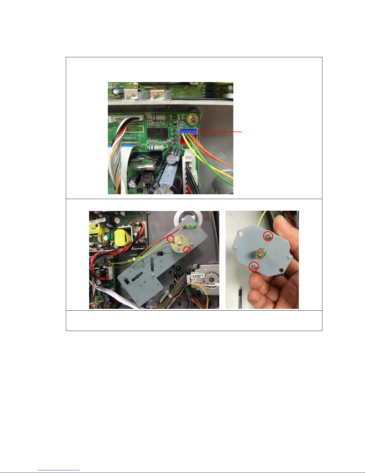
3.10 Replacing the DC Motor Module
1. Refer to section 3.1 to remove the electronics cover.
2. Disconnect the DC motor module connector from the main board.
3. Remove 4 screws from DC motor fixed plate.
4. Replace the DC motor module.
5. Reassemble the parts in the reverse procedures.
DC motor module
connector
Page 28
27
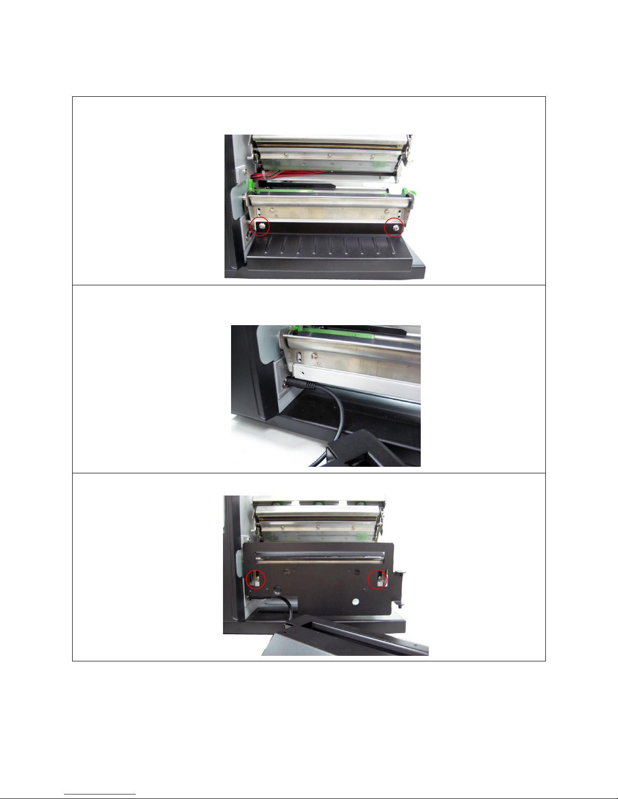
3.11 Cutter Module Installation (Option)
1. Open the printer right side cover.
2. Remove 2 screws to remove the lower front panel.
3. Plug the cutter mini DIN cable connector into the cutter/peel-off connector. The
triangle mark on the connector must be at the upper side.
4. Use 2 screws to lock the cutter fixing plate onto the front printer.
Page 29
28
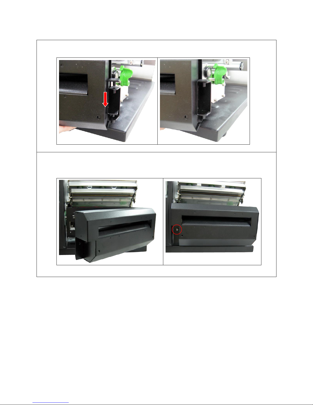
5. Place the cutter module into the cutter fixing plate. Please refer to the following fig.
6. Fasten the 1 screw at the cutter bracket to fix the cutter module to the printer
mechanism.
Page 30
29
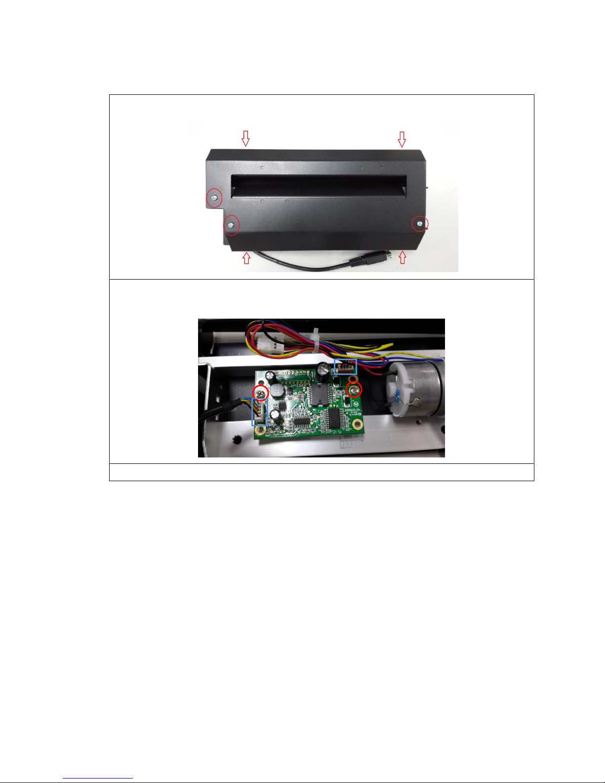
3.12 Replacing the Cutter Driver IC Board (Option)
1. Remove 7 screws on cutter cover.
2. Disconnect 2 connectors on the cutter driver IC board. Remove 2 screws to
replace the cutter driver IC board.
3. Reassemble the parts in the reverse procedures.
Page 31
30
3.13 Peel-off kit Installation
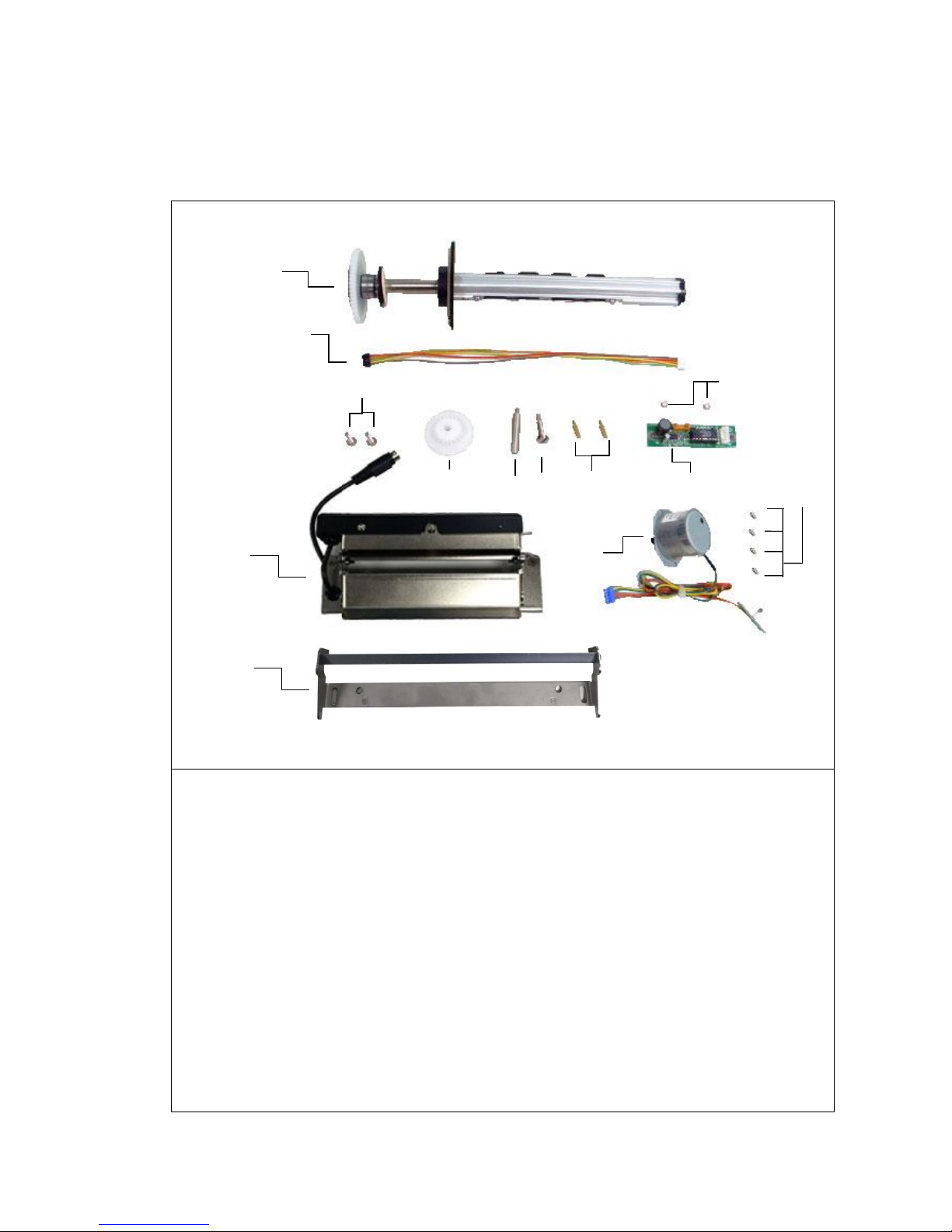
Peel-off kit parts list
1. Internal rewinder spindle
2. Harness for DC motor control board
3. Peel-off cover (Including peel-off sensor assembly)
4. Screw # 1
5. Gear
6. Pillar
7. Screw # 2
8. Copper pillar
9. Screw # 3
10. DC motor control board assembly
11. DC motor kit (Including DC motor and sensor assembly)
12. Screw # 4
13. Platen holder
1
2
3
4
5
6
7
8
9
10
11
12
13
Page 32
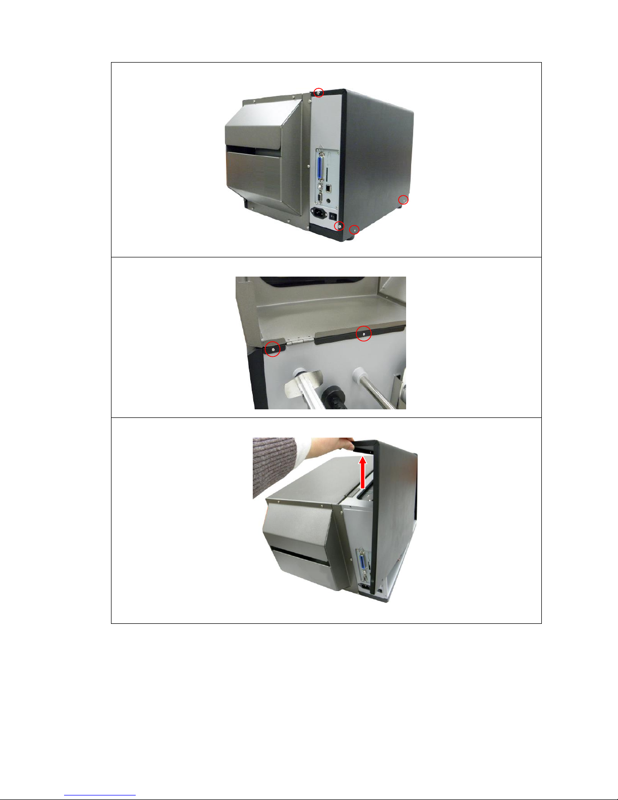
31
1. Remove 4 screws from printer electronics cover.
2. Open printer right side cover and remove two screws then close the cover.
3. Remove the electronics cover.
Page 33
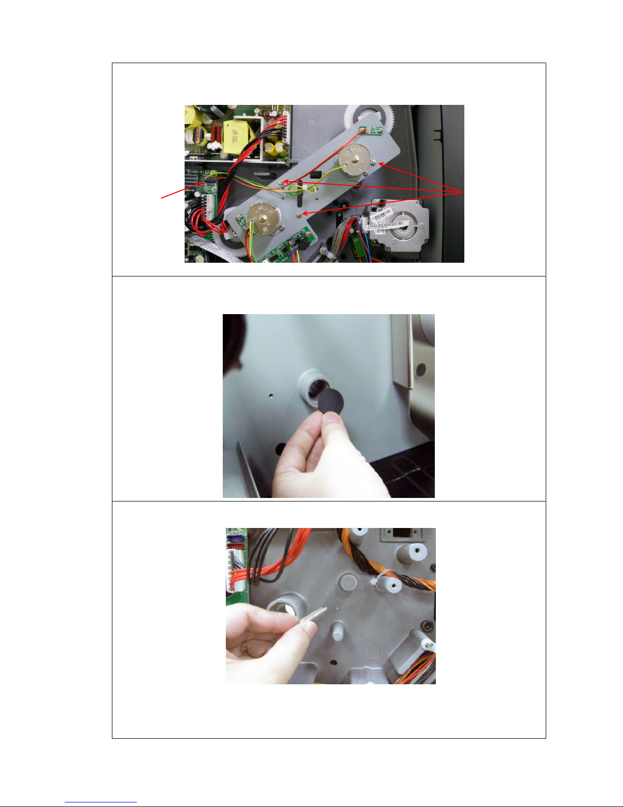
32
4. Remove 3 screws and 1 connector to remove the DC motor assembly. (DC
motor fixing plate)
5. Open the right side printer cover. Remove the dustproof cover from internal
rewinder spindle reserve hole.
6. Install the pillar to the printer. Please refer to the above fig.
Screws
Connector
(Blue)
Page 34
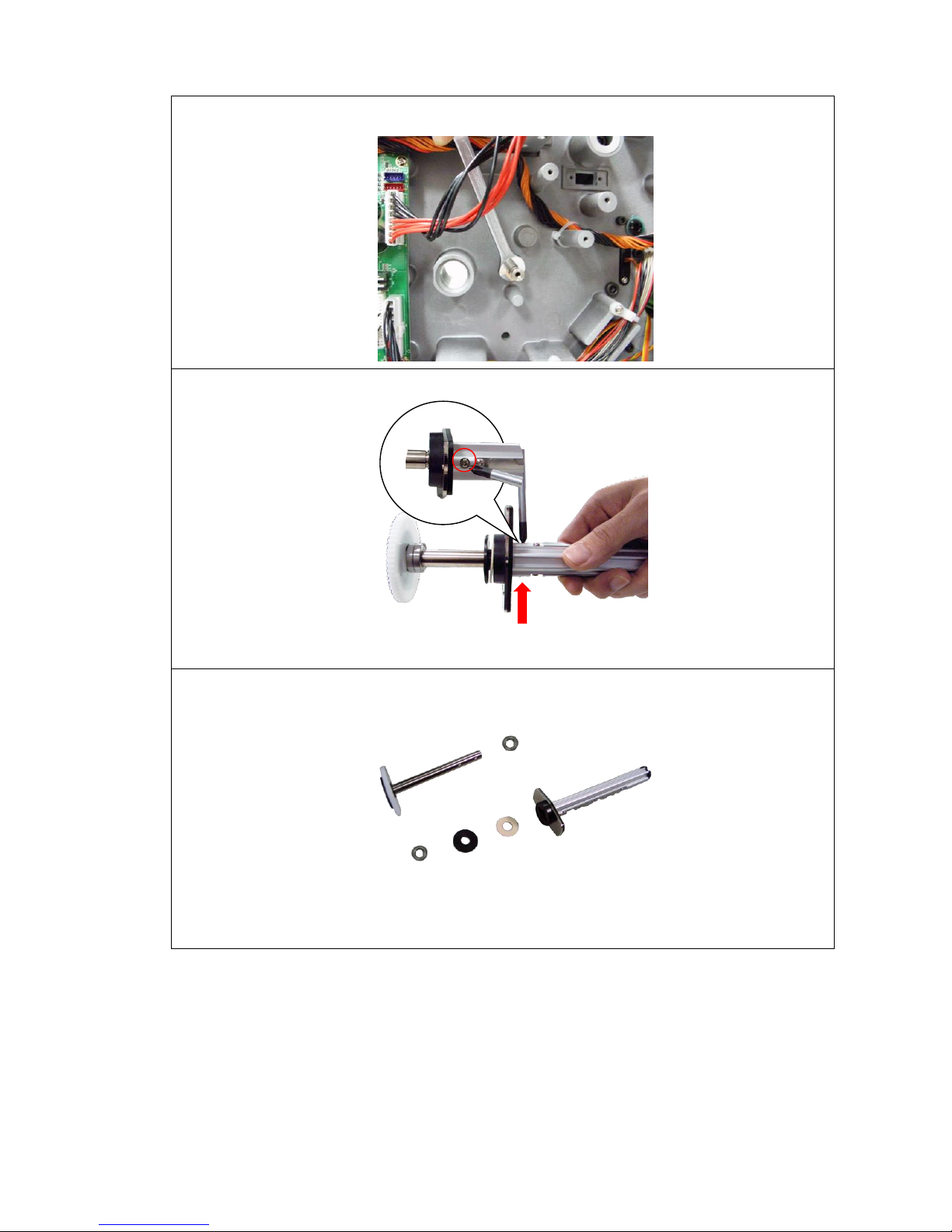
33
7. Use wrench (No. 7) to fasten the pillar.
8. Remove 2 screws from the internal rewinder spindle.
9. Separate the internal rewinder spindle and shaft as picture above.
Page 35
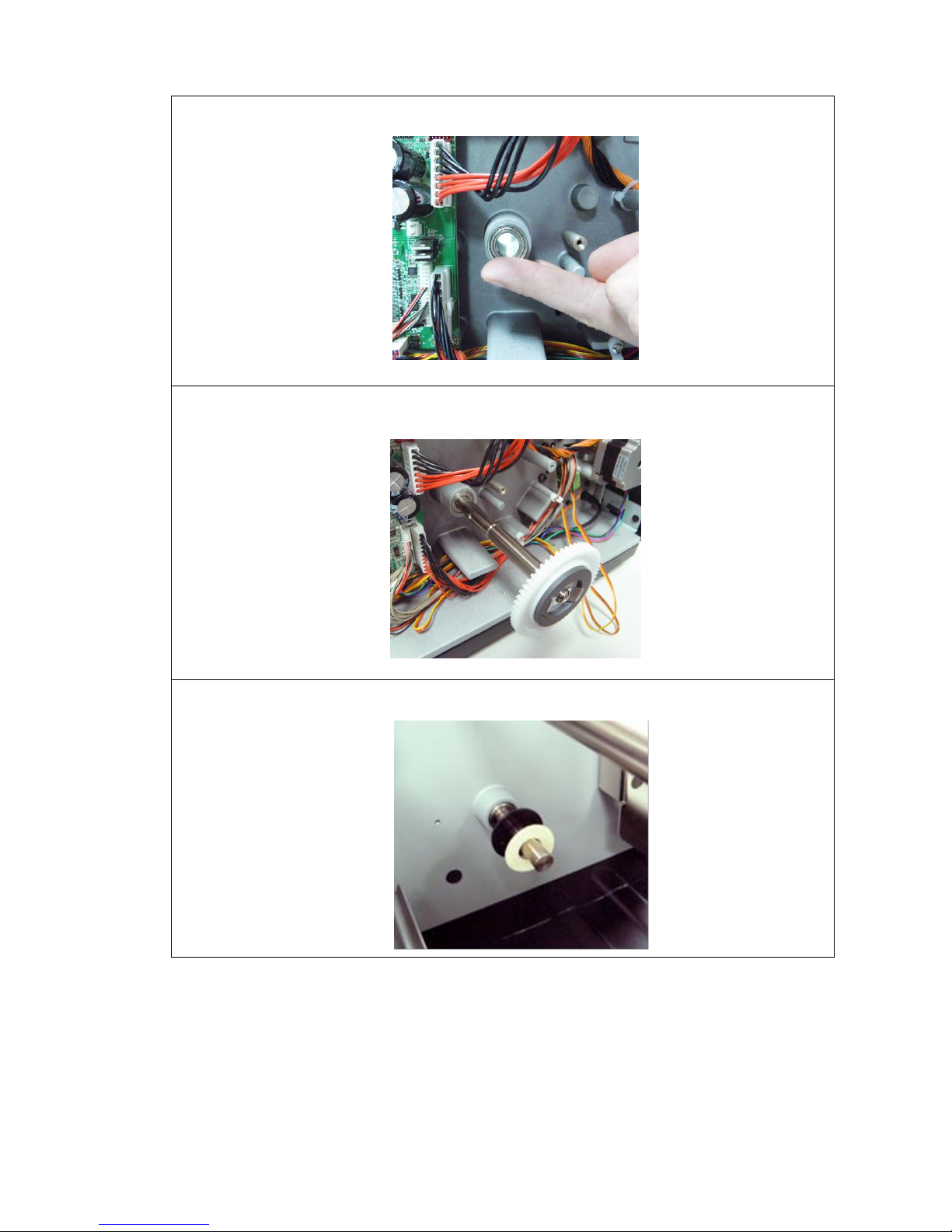
34
10. Put the bearing into the internal rewinder shaft hole. (Left side)
11. Put the bearing into the internal rewinder shaft hole then insert the gear shaft
into it.
12. Put the bearing (right side), felt fabric and gasket onto the shaft.
Page 36
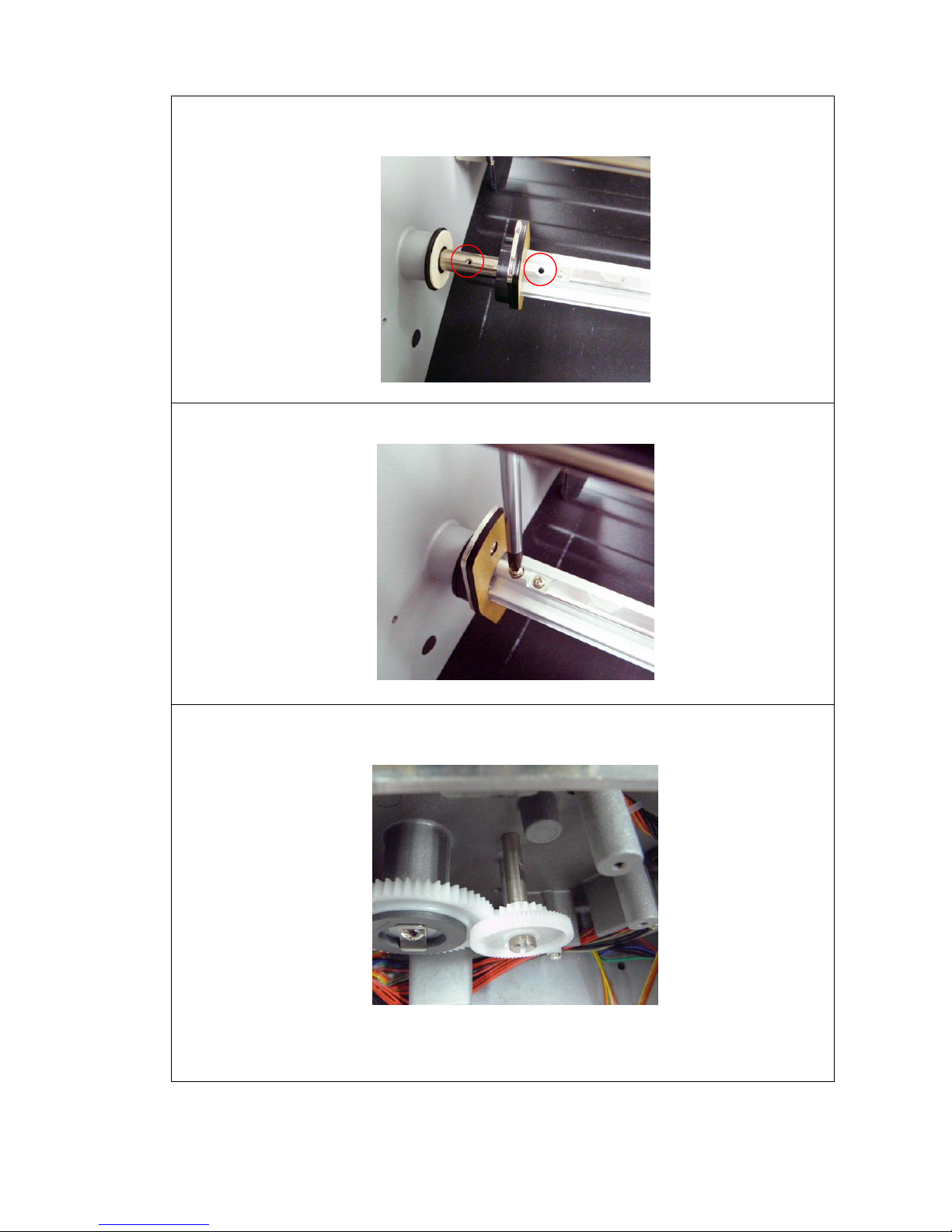
35
13. Insert the internal rewinder spindle to the shaft and fasten the screw.
Note: The spindle screw hole must be in alignment with the screw hole on
rewinder shaft
14. Rotate the spindle 180 degrees and fasten the other screw at the internal
rewinder spindle.
15. Use the screw (#2) to fasten the gear into the pillar by slotted screwdriver.
Note: Turn the gear to confirm that it works with internal rewinder gear.
Page 37
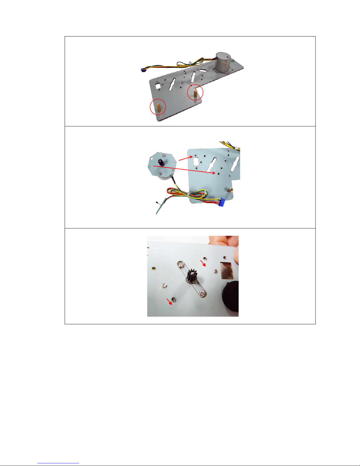
36
16. Install 2 copper pillars to the DC motor fixing plate.
17. Place the two locating protrusions on the motor into the locating holes on the
fixing plate.
18. Make sure the protrusions are at lower position of locating holes.
Page 38
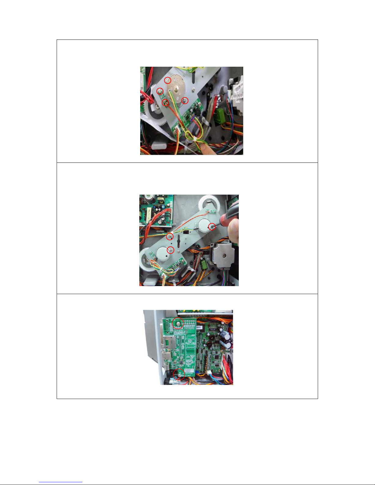
37
19. Use 4 screws (#4) to fix the DC motor and sensor board on the plate. Use
screws (#3) to fix the DC motor control board on the copper pillars. Plug the DC
motor kit harness into the DC motor control board.
20. Use 3 screws to fasten the DC motor plate to the printer mechanism. Plug the
DC motor control board harness into the DC motor control board. (White
connector)
21. Remove 2 screws from multi-interface board to remove the multi-interface
board.
Page 39
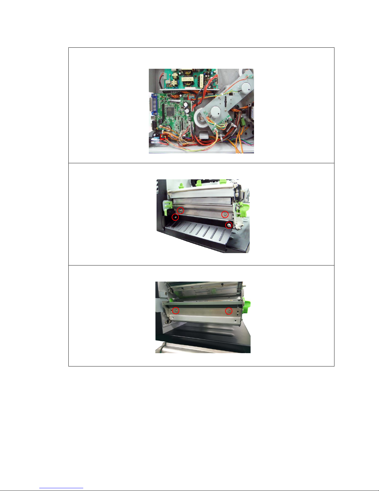
38
22. Connect the DC motor harness and the DC motor control board harness to main
board. Then, reassemble the parts in the reverse procedures.
23. Loosen 4 screws to remove lower front panel and platen holder.
24. Use 2 screws to install the new platen holder (No.13) as indicated.
Page 40
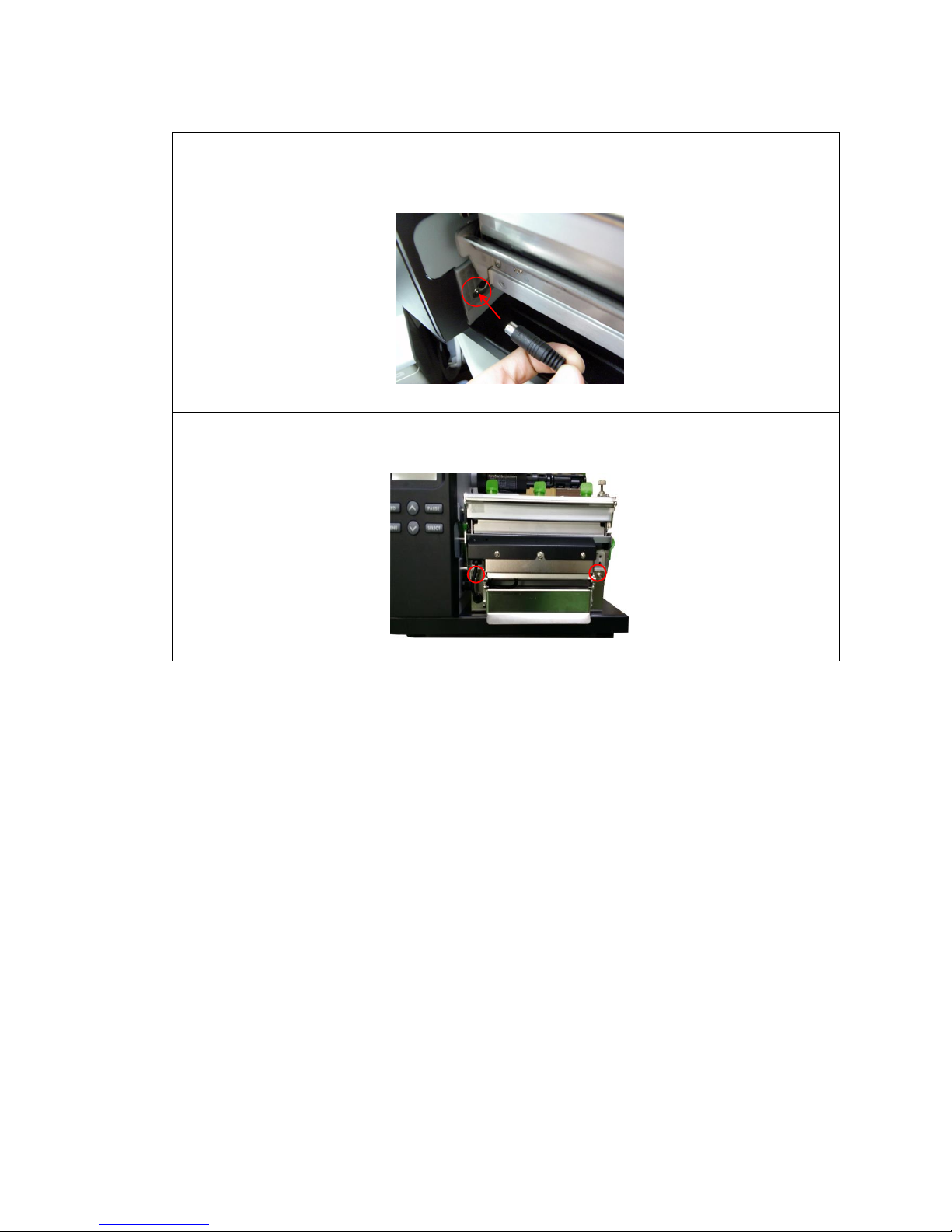
39
25. Plug the peel-off mini DIN cable connector into the peel-off connector and place
the cable in the cable cavity. The triangle mark on the connector must be at the
upper side.
26. Fasten 2 screws at the peel-off module to fix the peel-off module to the printer
mechanism.
Page 41
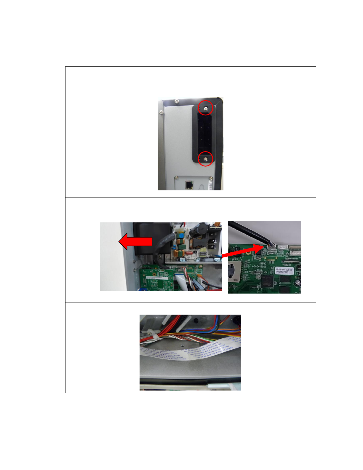
40
3.14 Slot-in Wifi Housing Installation (Option)
1. Fix the WiFi module with machine screw M3*6/ button head screws. Tightening
torque: 5KG
2. Insert the housing board cable to the main board.
3. Please make sure the LCD flat cable (white) is fixed on front of printer by a label.
Pull the cable to left
Page 42

41
4. TROUBLESHOOTING
4.1 Common Problems
The following guide lists the most common problems that might be encountered when
operating this bar code printer. If the printer still does not function after all suggested
solutions have been invoked, please contact the Customer Service Department of your
purchased reseller or distributor for assistance.
Problem
Possible Cause
Recovery Procedure
Power indicator does
not illuminate
* The power cord is not properly
connected.
* Plug the power cord in printer and outlet.
* Switch the printer on.
Carriage Open
* The printer carriage is open.
* Please close the print carriage.
No Ribbon
* Running out of ribbon.
* The ribbon is installed incorrectly.
* Supply a new ribbon roll.
* Please refer to the steps in user’s manual to
reinstall the ribbon.
No Paper
* Running out of label.
* The label is installed incorrectly.
* Gap/black-mark sensor is not
calibrated.
* Supply a new label roll.
* Please refer to the steps in user’s manual to
reinstall the label roll.
* Calibrate the gap/black-mark sensor.
Paper Jam
* Gap/black-mark sensor is not set
properly.
* Make sure label size is set properly.
* Labels may be stuck inside the printer
mechanism.
* Calibrate the gap/black-mark sensor.
* Set label size correctly.
UP: Fwd.
DOWN: Rev.
MENU: Exit
* Cutter jam.
* There is no cutter installed on the
printer.
* Cutter PCB is damaged.
* If the cutter module is installed, please press UP
or DOWN key to rotate the cutter up or down to
make the knife back to the right position.
* Remove the label.
* Make sure the thickness of label is less than
0.254 mm (10mil)
* Replace a cutter PCB.
Page 43

42
Not Printing
* Cable is not well connected to serial or
USB interface or parallel port.
* The serial port cable pin configuration
is not pin to pin connected.
* Re-connect cable to interface.
* If using serial cable,
- Please replace the cable with pin to pin
connected.
- Check the baud rate setting. The default baud
rate setting of printer is 9600,n,8,1.
* If using the Ethernet cable,
- Check if the Ethernet RJ-45 connector green
LED is lit on..
- Check if the Ethernet RJ-45 connector amber
LED is blinking.
- Check if the printer gets the IP address when
using DHCP mode.
- Check if the IP address is correct when using
the static IP address.
- Wait a few seconds let the printer get the
communication with the server then check the
IP address setting again.
* Chang a new cable.
* Ribbon and media are not compatible.
* Verify the ribbon-inked side.
* Reload the ribbon again.
* Clean the printhead.
* The print density setting is incorrect.
* Printhead’s harness connector is not well
connected with printheat. Turn off the printer
and plug the connector again.
* Check if the stepping motor is plugging in the
right connector.
* Check your program if there is a command
PRINT at the end of the file and there must have
CRLF at the end of each command line.
Memory full
( FLASH / DRAM )
* The space of FLASH/DRAM is full.
* Delete unused files in the FLASH/DRAM.
* The max. numbers of file of DRAM is 256 files.
* The max. user addressable memory space of
DRAM is 2048 KB.
* The max. numbers of file of FLASH is 256 files.
* The max. user addressable memory space of
FLASH is 6656KB.
SD card is unable to
use
* SD card is damaged.
* SD card doesn’t insert correctly.
* Use the non-approved SD card
manufacturer.
* Use the supported capacity SD card.
* Insert the SD card again.
* The supported SD card spec.
- 128MB
- 256MB
- 512MB
- 1GB
- 4GB SDHC CLASS 6
* Approved SD card manufacturers; SanDisk,
Transcend
PS/2 port does not
work
* Did not turn off power prior to plug in
the PS/2 keyboard.
* PS/2 keyboard is damaged.
* PS/2 keyboard doesn’t plug-in
correctly.
* There is no BAS file in the printer.
* Turn off printer power prior to plug in the PS/2
keyboard .
* Plug the PS/2 keyboard again.
* Make sure the keyboard is fine.
* Make sure if there is any BAS file downloaded
into printer.
Page 44
43
Poor Print Quality
* Ribbon and media is loaded incorrectly
* Dust or adhesive accumulation on the
printhead.
* Print density is not set properly.
* Printhead element is damaged.
* Ribbon and media are incompatible.
* The printhead pressure is not set
properly.
* Reload the supply.
* Clean the printhead.
* Clean the platen roller.
* Adjust the print density and print speed.
* Run printer self-test and check the printhead
test pattern if there is dot missing in the pattern.
* Change proper ribbon or proper label media.
* Adjust the printhead pressure adjustment knob.
- If the left side printout is too light, please adjust
the left side pressure adjustment knob to the
higher index (higher pressure). If the pressure
adjustment knob has been adjust to index “5”
and the poor print quality is still at the left side
of the printout, please adjust the pressure
adjustment knob to index “1” and use the
Z-axis adjustment knob to fine tune the
pressure.
- If the right side printout is too light, please
adjust the right side pressure adjustment knob
to the higher index (higher pressure) to
improve the print quality.
* If the label thickness is more than 0.22 mm, the
print quality might be not good enough, please
adjust the heater line adjustment screw counter
clockwise to get the best print quality.
* The release lever does not latch the printhead
properly.
LCD panel is dark and
keys are not working
* The cable between main PCB and LCD
panel is loose.
* Check if the cable between main PCB and LCD
is secured or not.
LCD panel is dark but
the LEDs are light
* The printer initialization is
unsuccessful.
* Turn OFF and ON the printer again.
* Initialize the printer.
LCD panel is dark and
LEDs are lit on, but
the label is feeding
forward
* The LCD panel harness connector is
loose.
* The LCD panel harness connector is plugged
upside down.
Ribbon encoder
sensor doesn’t work
* The ribbon encoder sensor connector
is loose.
* Fasten the connector.
Ribbon end sensor
doesn’t work
* The connector is loose.
* The ribbon sensor hole is covered with
dust.
* Check the connector.
* Clear the dust in the sensor hole by the blower.
Cutter is not working
* The connector is loose.
* Plug in the connect cable correctly.
Label feeding is not
stable (skew) when
printing
* The media guide does not touch the
edge of the media.
* If the label is moving to the right side, please
move the label guide to left.
* If the label is moving to the left side, please
move the label guide to right.
Skip labels when
printing
* Label size is not specified properly.
* Sensor sensitivity is not set properly.
* The media sensor is covered with dust.
* Check if label size is setup correctly.
* Calibrate the sensor by Auto Gap or Manual
Gap options.
* Clear the GAP/Black-mark sensor by blower.
The left side printout
position is incorrect
* Wrong label size setup.
* The parameter Shift X in LCD menu is
incorrect.
* Set the correct label size.
* Press [MENU] [SELECT] x 3 [DOWN] x 5
[SELECT] to fine tune the parameter of Shift
X.
Page 45

44
Missing printing on
the left or right side of
label
* Wrong label size setup.
* Set the correct label size.
RTC time is incorrect
when reboot the
printer
* The battery has run down.
* Check if there is a battery on the main board.
Multi interface board
doesn’t work
* The installation is incorrect.
* Check if the board is plugged in the right
connector.
Power and Error LEDs
are blinking fast
* Power switch OFF and ON too fast.
* Turn off the printer and wait all LEDs are dark,
and turn on the printer again.
Wrinkle Problem
* Printhead pressure is incorrect.
* Ribbon installation is incorrect.
* Media installation is incorrect.
* Print density is incorrect.
* Media feeding is incorrect.
* Make sure the label guide touch the edge of the
media guide.
* Make sure label, paper core and ribbon are set
at the center of the spindle.
Gray line on the blank
label
* The printhaed is dirty.
* The platen roller is dirty.
* Clean the printhead.
* Clean the platen roller.
Irregular printing
* The printer is in Hex Dump mode.
* The RS-232 setting is incorrect.
* Turn off and on the printer to skip the dump
mode.
* Re-set the Rs-232 setting.
Page 46
45
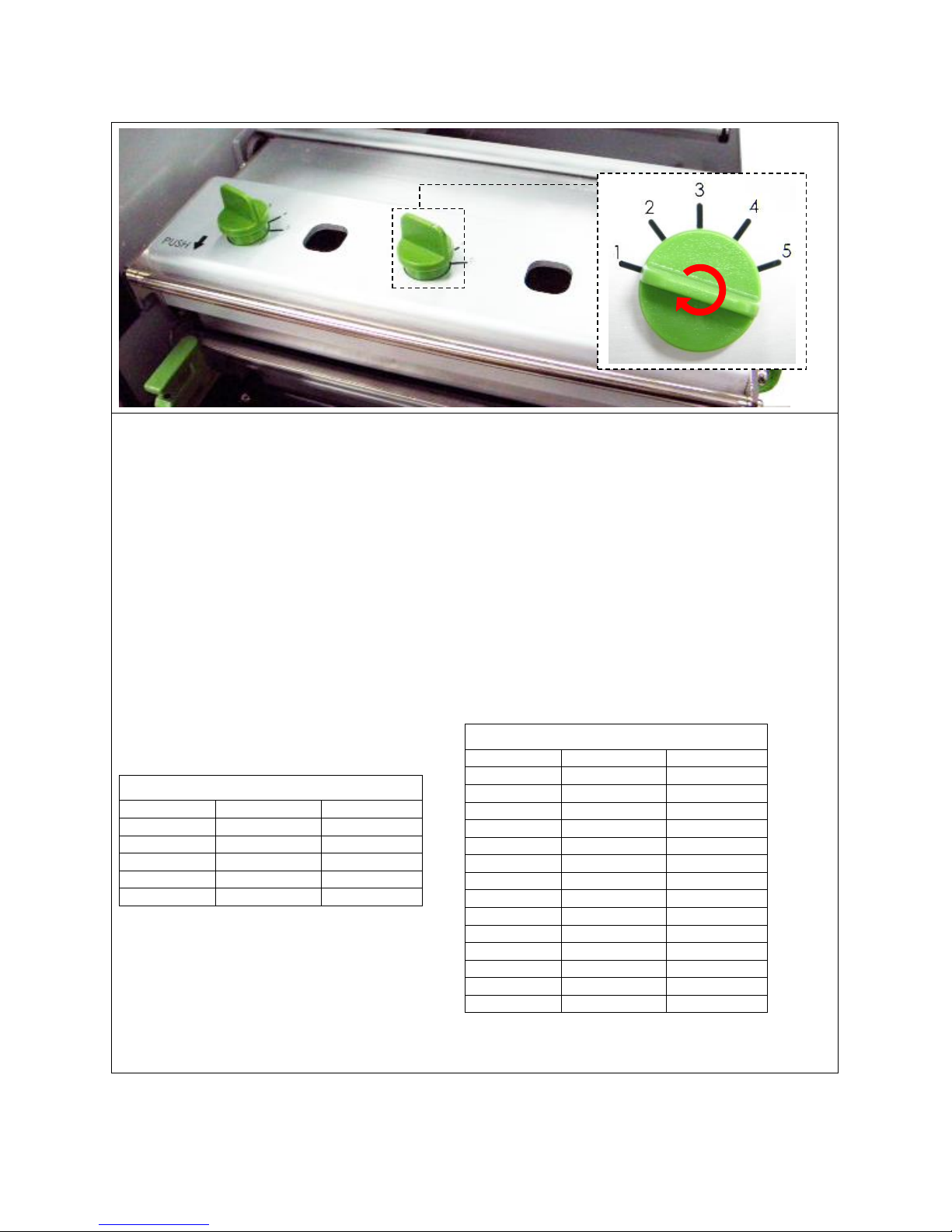
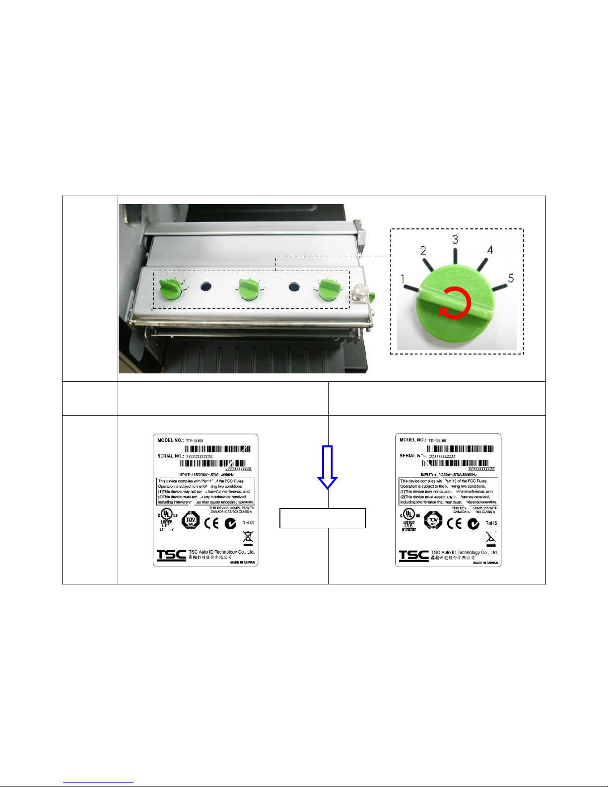
4.2 Print Head Pressure Adjustment Knob
There are two conditions that will need to adjust the print head pressure.
1. Print with thick media
If media thickness is larger than 0.19 mm, the larger pressure is required to get good
quality printout.
2. Edge alignment media
The media alignment is designed at the left edge of mechanism to keep the
pressure balance between print head, media and ribbon.
There are 5 levels of pressure for adjustment. Level 1 is the minimum pressure and level 5 is
the maximum pressure.
For example, if the label width is 6”, adjust both print head pressure adjustment knobs to the
same level. If the label is less than 2” wide, increase the left side print head pressure by
rotating the adjustment knob clockwise and decrease the right side pressure by rotating the
adjustment knob counter-clockwise to level 1. If the left side print head adjustment knob
setting has been set to 5 (the highest pressure index) than increase the middle print head
pressure.
Please refer to the following pressure knob
adjustment recommendation.
6” width label
Left index
Middle index
Right index
1 1 1 2 2 2 3 3 3 4 4 4 5 5 5
2” width label
Left index
Middle index
Right index
2 1 1 3 1 1 4 1 1 5 1 1 2 2 1 3 2 1 3 3 1 4 2
1
4 3 1 4 4 1 5 2 1 5 3 1 5 4 1 5 5
1
Page 47
46
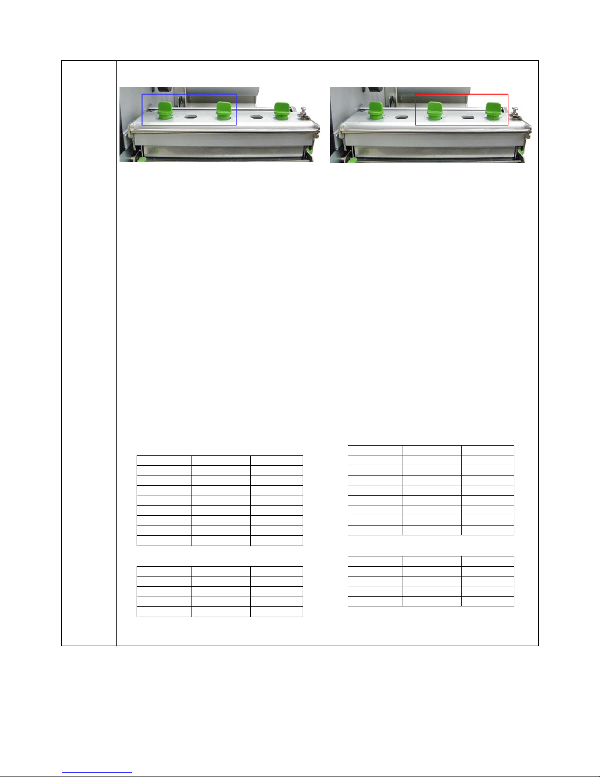
4.3 Mechanism Fine Adjustment to Avoid Ribbon Wrinkles
This printer has been fully tested before delivery. There should be no ribbon wrinkle
presented on the media for general-purpose printing application. Ribbon wrinkle is related to
the media thickness, print head pressure balance, ribbon film characteristics, print darkness
setting…etc. In case the ribbon wrinkle happens, please follow the instructions below to
adjust the printer parts.
Adjustable
Printer
Parts
Symptom
1. Wrinkle happens from label lower left to
upper right direction (“ˊ”)
2. Wrinkle happens from label lower right to
upper left direction (“ˋ”)
Wrinkle
Example
Feed direction
Page 48
47
Adjust the print head pressure adjustment knob
The print head pressure adjustment knob has 5
levels of settings. Clockwise direction adjustment
is to increase the print head pressure. Counter
Clockwise adjustment can decrease the print head
pressure.
If the wrinkle on the label starts from the lower left
side to upper right side, please do following
adjustment.
1. Decrease the right side print head pressure
adjustment knob setting 1 level per each
adjustment then print the label again to check if
wrinkle is gone.
2. If the right side print head adjustment knob
setting has been set to index 1 (the lowest
pressure index), please increase the left side
print head pressure.
3. If the left side print head adjustment knob
setting has been set to 5 (the highest pressure
index) the wrinkle can’t be avoided, please
increase the middle print head pressure knob.
4. If the wrinkle can’t be avoided, please refer to
next chapter to adjust the Z-axis mechanism
adjustment knob.
Pressure knob adjustment reference:
6” label
Left index
Middle index
Right index
2 1 1
3 1 1
4 1 1 5 1 1 5 2 1 5 3
1
5 4 1
5 5 1
3” label
Left index
Middle index
Right index
2 2 1 3 3 1 4 4 1 5 5
1
Adjust the print head pressure adjustment knob
The print head pressure adjustment knob has 5
levels of settings. Clockwise direction adjustment is
to increase the print head pressure. Counter
Clockwise adjustment can decrease the print head
pressure.
If the wrinkle on the label starts from the lower right
side to upper left side, please do following
adjustment.
1. Decrease the left side print head pressure
adjustment knob setting 1 level per each
adjustment then print the label again to check if
wrinkle is gone.
2. If the left side print head adjustment knob level
has been set to index 1 (the lowest index), please
increase the right side print head pressure.
3. If the right side print head adjustment knob setting
has been set to 5 (the highest pressure index) the
wrinkle can’t be avoid, please increase the middle
print head pressure knob.
4. If the wrinkle can’t be avoided, please refer to
next chapter to adjust the Z-axis mechanism
adjustment knob.
Pressure knob adjustment reference:
6” label
Left index
Middle index
Right index
1 1 2 1 1 3 1 1 4 1 1
5
1 2 5
1 3 5 1 4 5 1 5 5
3” label
Left index
Middle index
Right index
1 2 2
1 3 3
1 4 4
1 5 5
Left knob
Right knob
Middle knob
Middle knob
Page 49
48
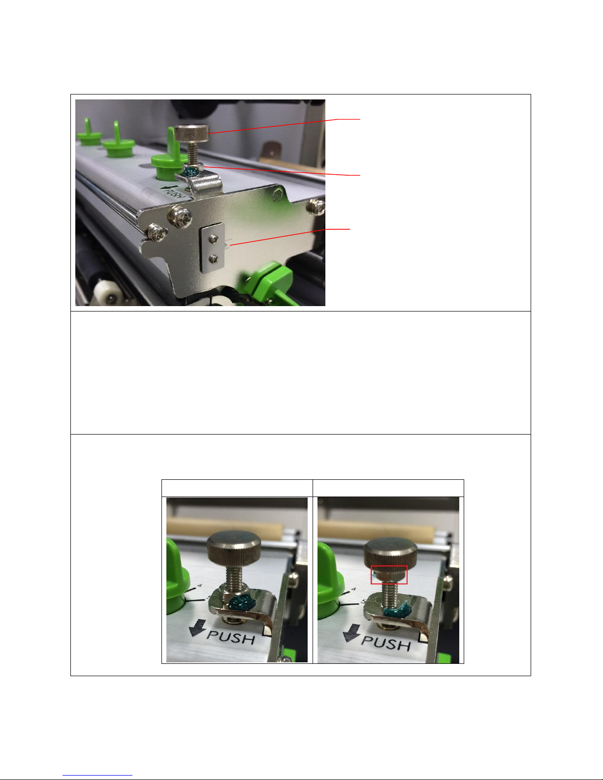
4.4 Z-axis Mechanism Adjustment Knob
For narrow media, If change the print head pressure adjustment knob setting can’t get the
printout without ribbon wrinkle, the Z-axis mechanism adjustment knob should be adjusted
to get the satisfied printout. This Z-axis mechanism adjustment knob is used to fine tune the
right side pressure of print head. Before fine tune the print head right side pressure, please
set the pressure adjustment knob to index “1” then use use the Z-axis adjustment knob to
fine tune the right side print head pressure. Please refer to the adjustment steps as below.
1. Loosen the fixing nut to the top of knob. (Move the nut only.)
Factory default
Loosen the nut to the top
Z-axis mechanism
adjustment knob
Fixing nut
Indicator (The default
position is set at the lowest
line.)
Page 50
49
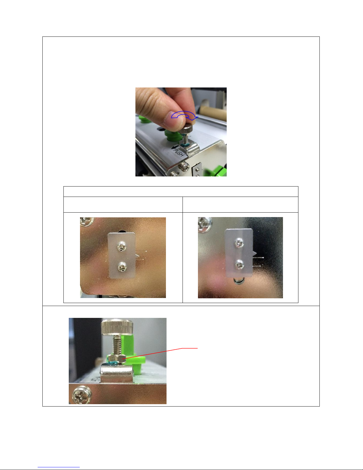
2. Please be noted that print head right pressure find turn should be done by try-and-error.
Rotate the Z-axis mechanism adjustment knob clockwise for a few degrees by
screwdriver and print again to check if the ribbon wrinkle remains. If the wrinkle still
remains, please turn the Z-axis mechanism adjustment knob clockwise about 1/4 circle
each time for adjustment.
Marker position
Factory default position
In Z-axis mechanism adjustment
knob function position
3. Screw the fixing nut for fixed this print head pressure.
Fixing nut
Page 51
50
5. MAINTENANCE
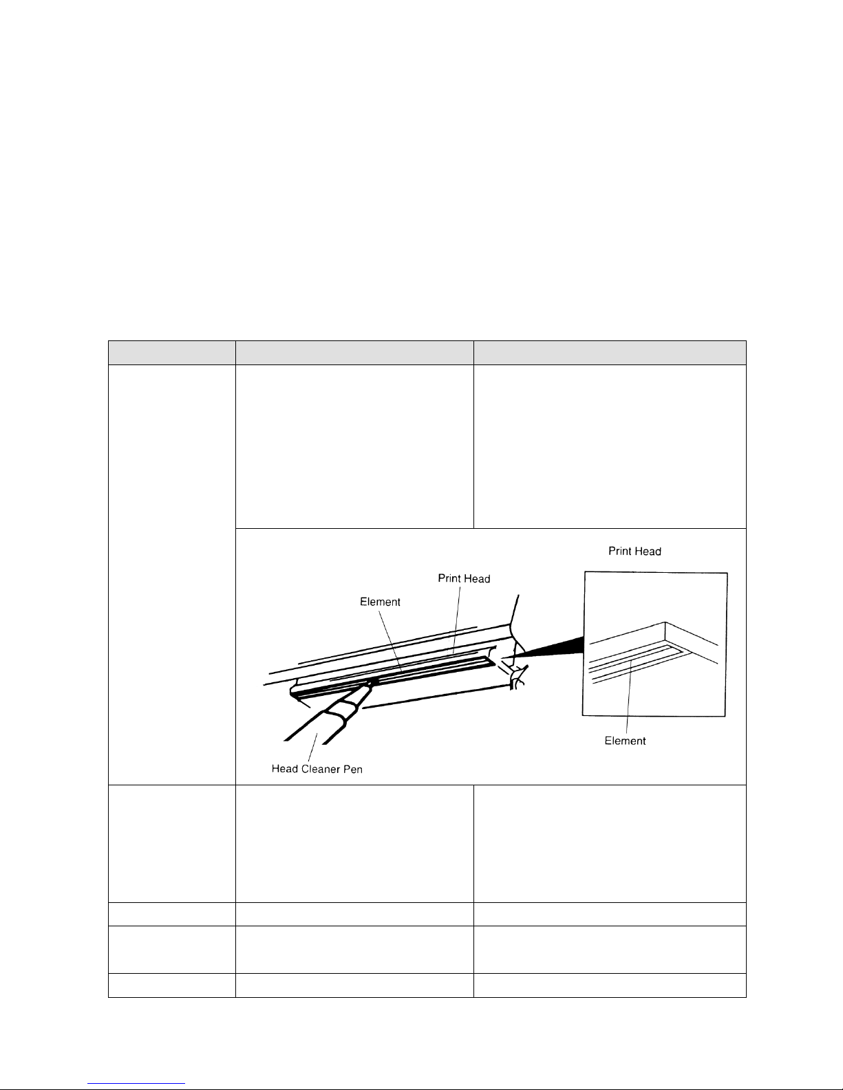
This session presents the clean tools and methods to maintain your printer.
1. Please use one of following material to clean the printer.
Cotton swab (Head cleaner pen)
Lint-free cloth
Vacuum / Blower brush
100% ethanol
2. The cleaning process is described as following
Printer Part
Method
Interval
Print Head
1. Always turn off the printer
before cleaning the print head.
2. Allow the print head to cool for
a minimum of one minute.
3. Use a cotton swab (Head
cleaner pen) and 100% ethanol
to clean the print head surface.
Clean the print head when changing a
new label roll
Platen Roller
1. Turn the power off.
2. Rotate the platen roller and
wipe it thoroughly with 100%
ethanol and a cotton swab, or
lint-free cloth.
Clean the platen roller when changing
a new label roll
Sensor
Compressed air or vacuum
Monthly
Exterior
Wipe it with water-dampened
cloth
As needed
Interior
Brush or vacuum
As needed
Page 52

51
Note:
Do not touch printer head by hand. If you touch it careless, please use ethanol to clean
it.
Please use 100% Ethenol. DO NOT use medical alcohol, which may damage the printer
head.
Regularly clean the print head and supply sensors once change a new ribbon to keep
printer performance and extend printer life.
Page 53
52
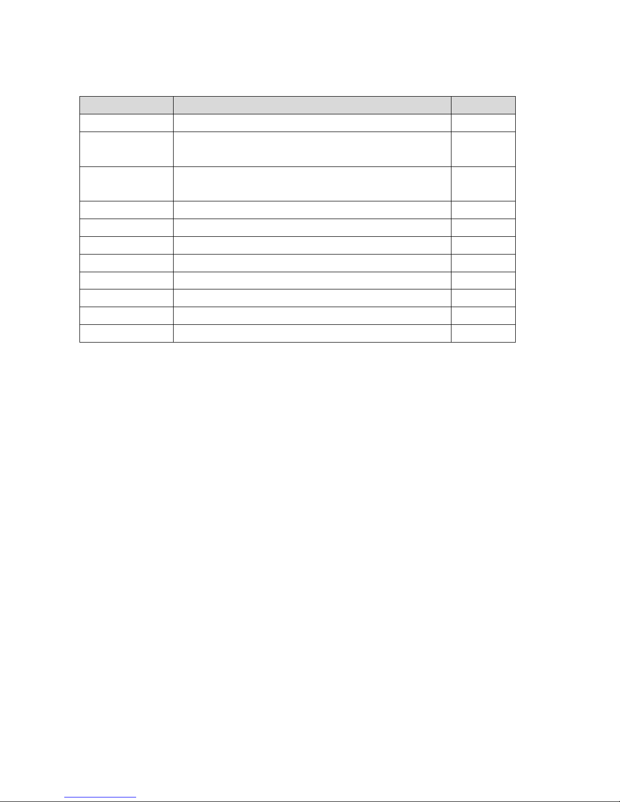
UPDATE HISTORY
Date
Content
Editor
2015/10/2
Add section 3.12 (Replacing the cutter driver IC board)
Camille
2015/10/21
Modify section 1.1 (Recommended SD card
specification)
Camille
2016/04/20
Add section 3.13 (Peel-off kit Installation) & 3.14 (Slot-in Wifi
Housing Installation (Option))
Kate
Page 54

53
Corporate Headquarters Li Ze Plant
9F., No.95, Minquan Rd., Xindian Dist., No.35, Sec. 2, Ligong 1st Rd., Wujie Township,
New Taipei City 23141, Taiwan (R.O.C.) Yilan County 26841, Taiwan (R.O.C.)
TEL: +886-2-2218-6789 TEL: +886-3-990-6677
FAX: +886-2-2218-5678 FAX: +886-3-990-5577
Web site: www.tscprinters.com
E-mail: [email protected]
TSC Auto ID Technology Co., Ltd.
 Loading...