

Page 1

USER’S
MANUAL
TTP-246M/344M
THERMAL TRANSFER / DIRECT THERMAL
BAR CODE PRINTER
Page 2

Page 3

i
CONTENTS
1. PRODUCT INTRODUCTION................................................1
1.1 Compliances..................................................................................................... 1
2. GETTING STARTED.............................................................2
2.1 Unpacking and Inspection.............................................................................. 2
2.2 Equipment Checklist...................................................................................... 2
2.3 Printer Parts .................................................................................................. 3
2.4 Buttons, Indicators and adjustment knobs..................................................... 4
3. Set Up....................................................................................7
3.1 Setting Up the Printer..................................................................................... 7
3.2 Ribbon Installation.......................................................................................... 7
3.3 Label Roll Installation ..................................................................................... 8
3.4 Cutter Module Installation (Option)................................................................. 9
3.5 Peeler Kit Installation (Option)...................................................................... 10
3.6 Loading Label For Peel-off Mode................................................................. 16
3.7 Self-test........................................................................................................ 18
3.8 Dump Mode.................................................................................................. 19
4. USING TTP-246M/344M .....................................................21
4.1 Power-on Utilities ........................................................................................... 21
4.1.1 Gap/Black Mark Sensor Calibration Utility............................................. 21
4.1.2 Printer Initialization................................................................................ 22
4.2 Troubleshooting Guide................................................................................... 24
5. PRINTER CLEANING .........................................................26
5.1 Print Head Cleaning ....................................................................................... 26
5.2 Printer Cover Cleaning................................................................................... 26
5.3 Internal Parts Cleaning................................................................................... 26
APPENDIX LCD Control Panel Operation Map ......................27
Page 4

Page 5

1
1. PRODUCT INTRODUCTION
Thank you very much for purchasing TSC TTP-246M/344M bar code printer.
TTP-246M/344M comes with rugged steel construction and durable metal
mechanism ensuring the ability to work under extreme industrial applications.
TTP-246M/344M is equipped with a 32-bit RISC multi-tasking processor, which
offers up to 6 ips for 246M and 4”/sec for 344M print speed. With back-lit LCD
display, printer status can be managed easier and operated more user friendly.
The moveable sensor design can meet wide range of label media. All of the most
frequently used bar code formats are available in TTP-246M/344M. Fonts and
bar codes can be printed in any one of the four directions. This printer provides a
choice of five different sizes of alphanumeric font, OCR-A, OCR-B and one true
type font.
TTP-246M/344M is the most cost-effective and high performance in its class!
1.1 Compliances
FCC
CFR 47, Part 15/CISPR 22 3
rd
Edition: 1997, Class A
ANSI C63.4: 2003
Canadian ICES-003
CE
EN 55022: 1998 Class A
EN 61000-3-2: 1995 Class A
Amendment 1: 1998
Amendment 2: 1998
Amendment 14: 2000
EN 61000-3-3: 1995
EN55024: 1998
C-TICK
AS/NZS CISPR 22 (Class A)
TUV/GS: EN 60950-1: 2001
UL, CUL
BSMI
CCC
Page 6

2
2. GETTING STARTED
2.1 Unpacking and Inspection
After receiving the bar code printer, carefully inspect the device and its packaging.
The printer is specially packaged to withstand damage in shipping. In case of
evident damage, contact the carrier directly to specify the nature and extent of
damage. Please retain the packaging materials in case you need to reship the
printer.
2.2 Equipment Checklist
One printer unit
One paper core for ribbon take up spindle
One quick installation guide
One power cord
One centronics interface cable
One 3” paper core adapter
One Windows labeling software/Windows driver CD disk
One 1” core label roll fixing tab
Separately purchased items may also be included. These additional items may
include:
Cutter module
Peeler kit module (included peel sensor)
Stand-alone LCD keyboard (KP-200, KU-007 series)
Memory module
Internal Ethernet print server
External 802.11b/g wireless print server
If any part is missing, please contact the Customer Service Department of your
purchased reseller or distributor.
Page 7

3
2.3 Printer Parts
Figure 1. Printer front view
Figure 2. Printer rear view
External Label
Feed Opening
Centronics Port
RS-232C Port
Power Switch
Power Supply
Connector
USB port
LED indicator
LCD Display
Printer Right
Side Cove
r
Buttons
Page 8

4
Figure 3. Printer interior view
2.4 Buttons, Indicators and adjustment knobs
Power Indicator
When the printer is in the power-on condition, the Power indicator is lit on.
On-Line Indicator
This green On-Line indicator is lit on when the printer is ready; the On-Line
indicator blinks when pressing PAUSE button.
Error Indicator
The red Error indicator illuminates in the event of a printer error, such as
memory full, carriage open, cutter error and so forth.
MENU/SELECT Button
Provided with a built-in menu, the printer allows the user to directly set printing
parameters or view printer status on the LCD display.
Print Head Lift Lever
Ribbon Rewind Spindle
Ribbon Supply Spindle
Label Spindle
Media Guide Bar
Label Guide
Ribbon Tension
Adjustment Knob
Print Head Pressure
Adjustment Knob
Page 9

5
Press the MENU button to enter printer setup mode. Press the MENU button
again to proceed the cursor to the next item.
The setup is comprised of these major items: Printer Setup, Sensor Setup,
System Setup, File Setup and Printer Test. For more information, please refer to
Appendix for the structure and operation logic of the menu.
PAUSE/EXE/INC Button
This button combines three functions:
A. PAUSE button if the printer is in the Ready status. By pressing the PAUSE
button: (1) the printer stops at the completion of printing of the current
label,(2) the On-Line LED flashes, and (3) the printer holds all data in
memory. This allows for trouble-free replacement of label stock and thermal
transfer ribbon. A second depression of the PAUSE button will restart the
printer.
B. EXE/INC button if in the setup mode. Press EXE/INC button to increase the
value of parameters, or execute the selected item.
FEED/DEC Button
This button also has dual functions: Feed one label and decrease the value of
parameters.
Press the FEED button, the printer will advance one label.
Press the DEC button to change parameter settings or exit the submenu.
Print Head Lift Lever
When opening the Print Head Lift Lever, On-Line LED is lit off, the LCD display
shows “Carriage Open”. After engage the print head lift lever, press the FEED
button, printer will re-register the label and then shows READY on the LCD
display, and the screen will return to ready condition.
Ribbon Tension Adjustment Knob
The ribbon tension adjustment knob offers 6 levels of tension to adjust for
different widths of ribbon. Turn the ribbon tension knob clockwise and you will
hear a light click sound as the gear changes. The level of rewind ribbon is from
loose to tight, level 0 to level 5. You will hear a louder click for level 1.
Print head Pressure Adjustment Knob
The print head adjustment knobs are used to fine tune print quality for
Page 10

6
different thickness of media. Turning the knobs adjusts the print head’s burn line
forward or backward as it relates to the platen roller.
Print head burn line adjustment knob
The print head adjustment knobs are used to fine tune print quality for different
thickness of media. Turning the knobs adjusts the print head’s burn line forward
or backward as it relates to the platen roller.
Caution: incorrectly adjusting these knobs can lead to poor print quality
and may cause damage to the printer. Proceed with caution.
The print head burn line default is set for general purpose printing media (plain
paper and paper thickness less than 0.20mm). The adjustment knobs default is
screwed to the end of thread.
Poor print quality when using paper thicker than 0.20mm may be due to the print
head burn line not being at the optimized position. To correct this, increase the
head pressure and adjust the knobs counter-clockwise to move print head burn
line forward then print again. Continue to adjust and test print as necessary until
the image is clear.
Note: The print head moves 0.7 mm for each 360 degree turn.
Figure 4. Print head adjustment knobs
***print head adjustment knobs
Page 11
7
3. Set Up
3.1 Setting Up the Printer
1. Place the printer on a flat, secure surface.
2. Make sure the POWER switch is off.
3. Connect the printer to the computer with the provided Centronics cable.
4. Plug the power cord into the AC power cord socket at the rear of the printer,
and then plug the power cord into a properly grounded power outlet.
3.2 Ribbon Installation
1. Open printer right side cover and lower front panel.
2. Disengage print head lift lever.
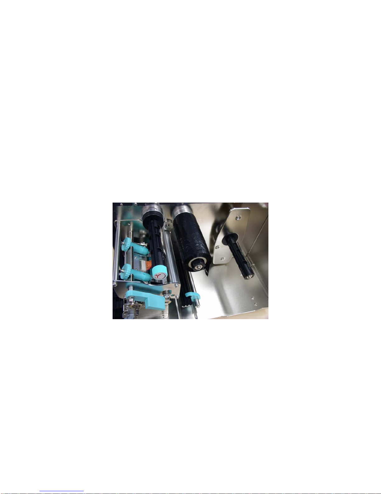
3. Install a new ribbon roll onto the ribbon supply spindle.
Notice : Ribbon should be placed to the left end of spindle.
Figure 5. Ribbon supply spindle installation
4. Place an empty paper core onto the ribbon rewind spindle. (The diameter of
empty paper core must be larger then 34 mm)
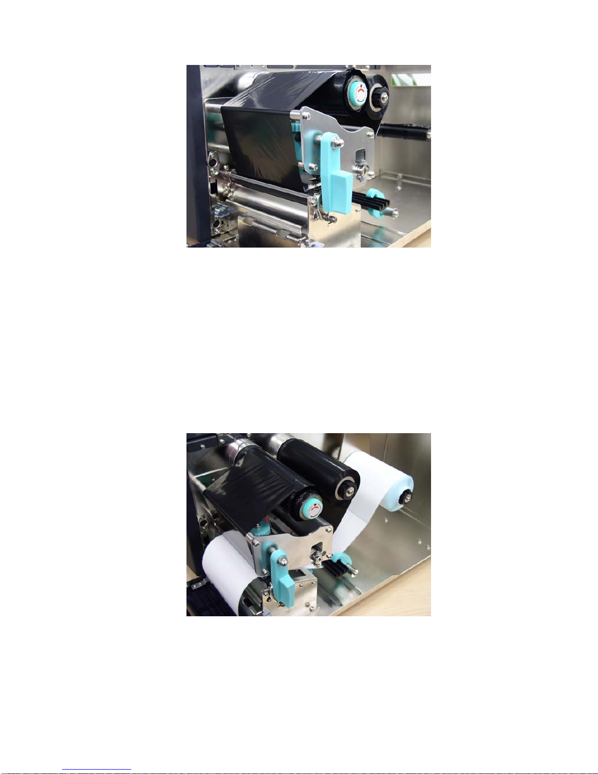
5. Pull the ribbon roll leading edge forward through the ribbon sensor, and
attach the ribbon leading edge (with a tape) to the empty paper core.
6. Manually rotate the ribbon rewind roll until the ribbon is properly stretched.
Page 12
8
Figure 6. Installation of thermal transfer ribbon
3.3 Label Roll Installation
1. Insert a new label roll into the label spindle.
2. Pull label roll leading edge forward through the black media guide bar,
gap/black mark sensor and place the label leading edge onto the platen
roller.
3. Adjust the label guide to meet the width of the label, and buckle it onto the
black media guide bar.
4. Engage the print head lift lever.
5. Close the lower front panel and printer cover.
6. Switch on the power. Now, the printer is ready to print.
Figure 7. Insert a label roll into label spindle.
Page 13
9
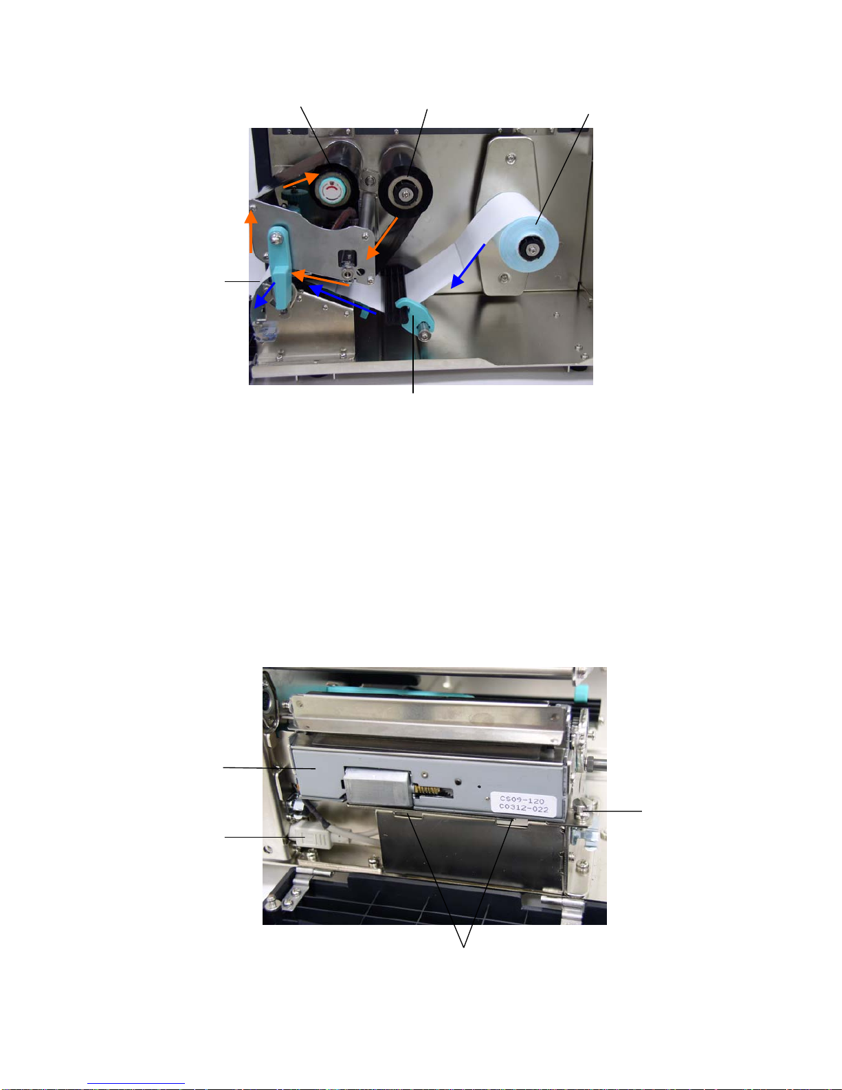
Figure 8. Ribbon & label installation path
3.4 Cutter Module Installation (Option)
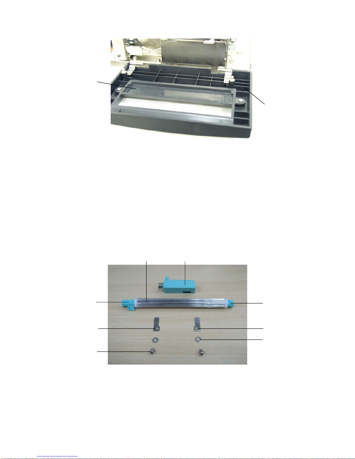
1. Remove the 2 screws of the peel-off panel and uninstall the peel-off panel if
it is installed in the front panel.
2. Plug the mini DIN cable into the socket of the cutter connector.
3. Install the cutter module.
Notice : The cutter module bracket should be mounted into the slots.
4. Fix the cutter module onto the printer cutter mount with a screw.
5. Install the Cutter Module Panel with 2 screws to the front panel.
Cutter Module
Ribbon Rewind Spindle
Ribbon Supply Spindle
Label Supply Roll
Label Guide
Screw
Mini Din Cable
Label
Slots
Page 14
10
Figure 9. Cutter module installation
3.5 Peeler Kit Installation (Option)
Checklist:
Cutter Module
Panel
Lower Front
panel
Peel off sensor assembly
Peel off roller
Left side spring leaf
Right side spring leaf
Washer
Screw
Peel off roller
right side bush
Peel off roller
left side bush
Page 15
11
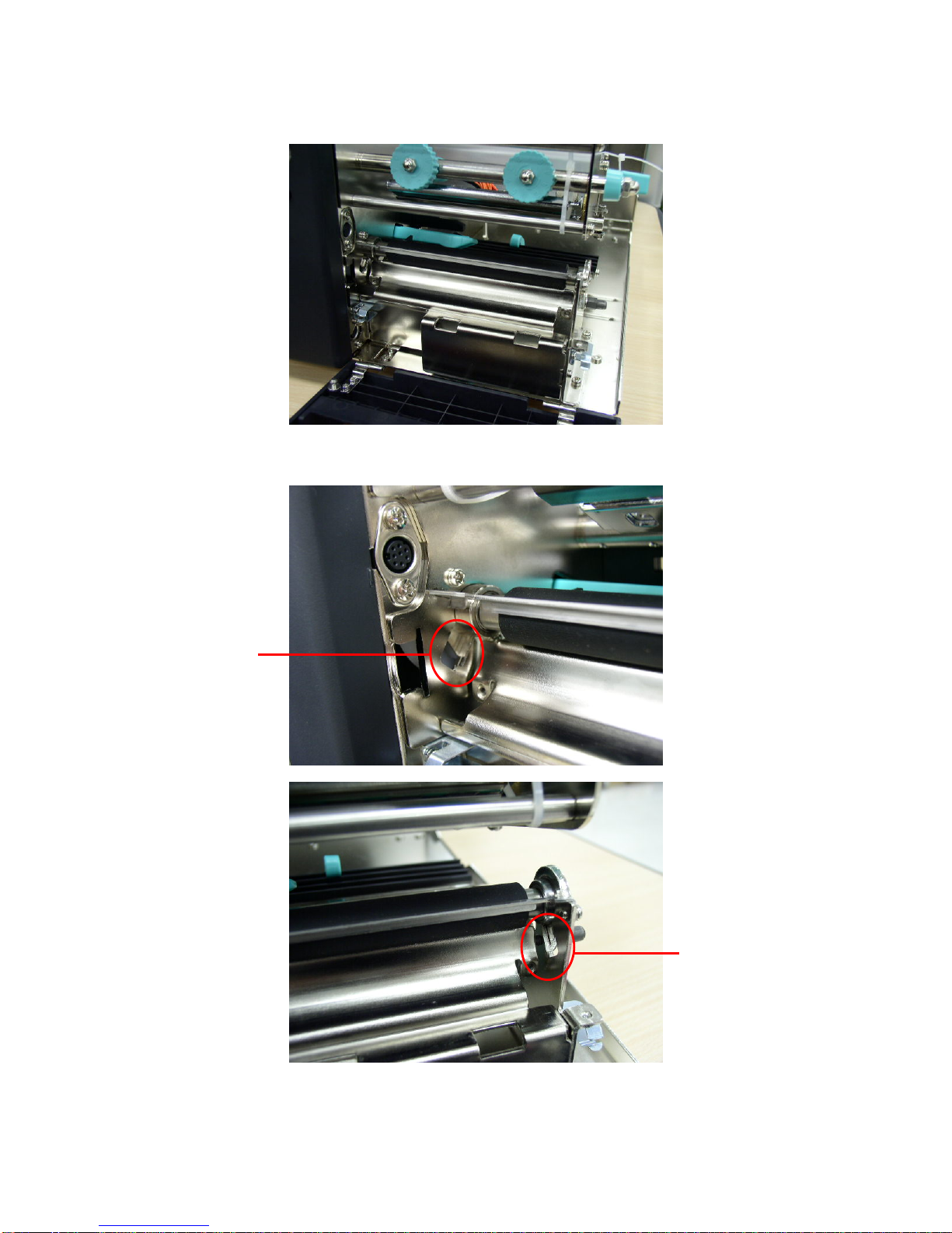
1. Open the lower front panel and the printer right side cover.
2. There is a notch near by the platen roller bearing.
Notch for peel off
roller left side
bush
Notch for peel off roller
right side bush
Page 16
12
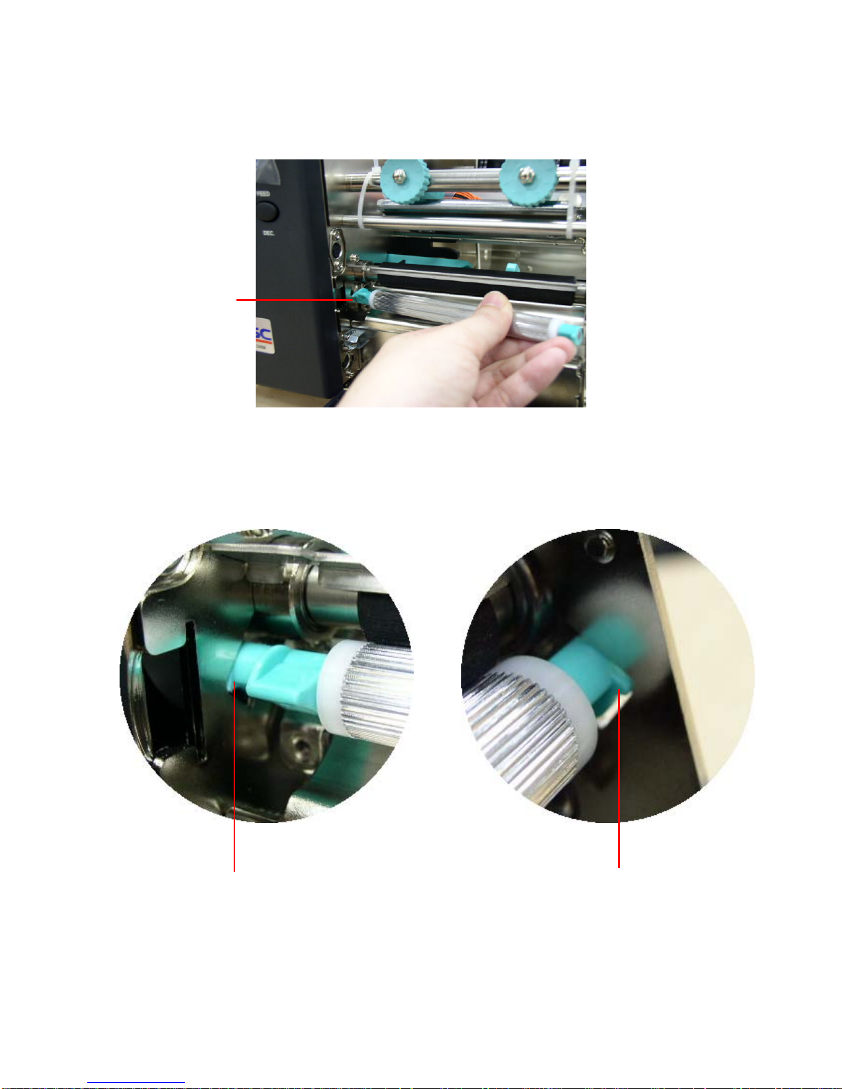
3.
Insert the peel off roller left side bush to the notch at the middle plate and insert
the peel off roller right side bush to the notch at the right frame. Please refer to
the magnified left and right side bush location for installation.
Insert the
left side
first.
Left side
Right side
Bush location
Bush location
Page 17
13
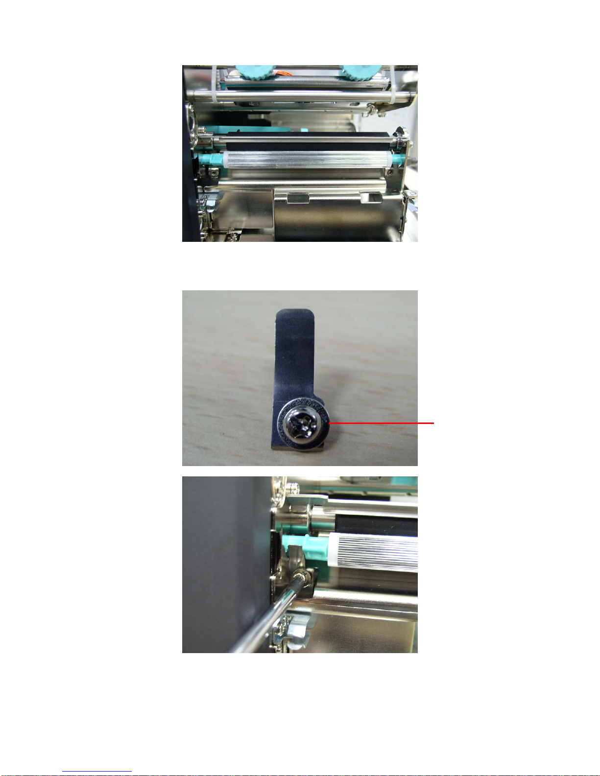
4. Fasten the leaf springs and washers with screws to fix the left and right side
bush.
Washer is placed
between leaf spring
and screw.
Page 18
14
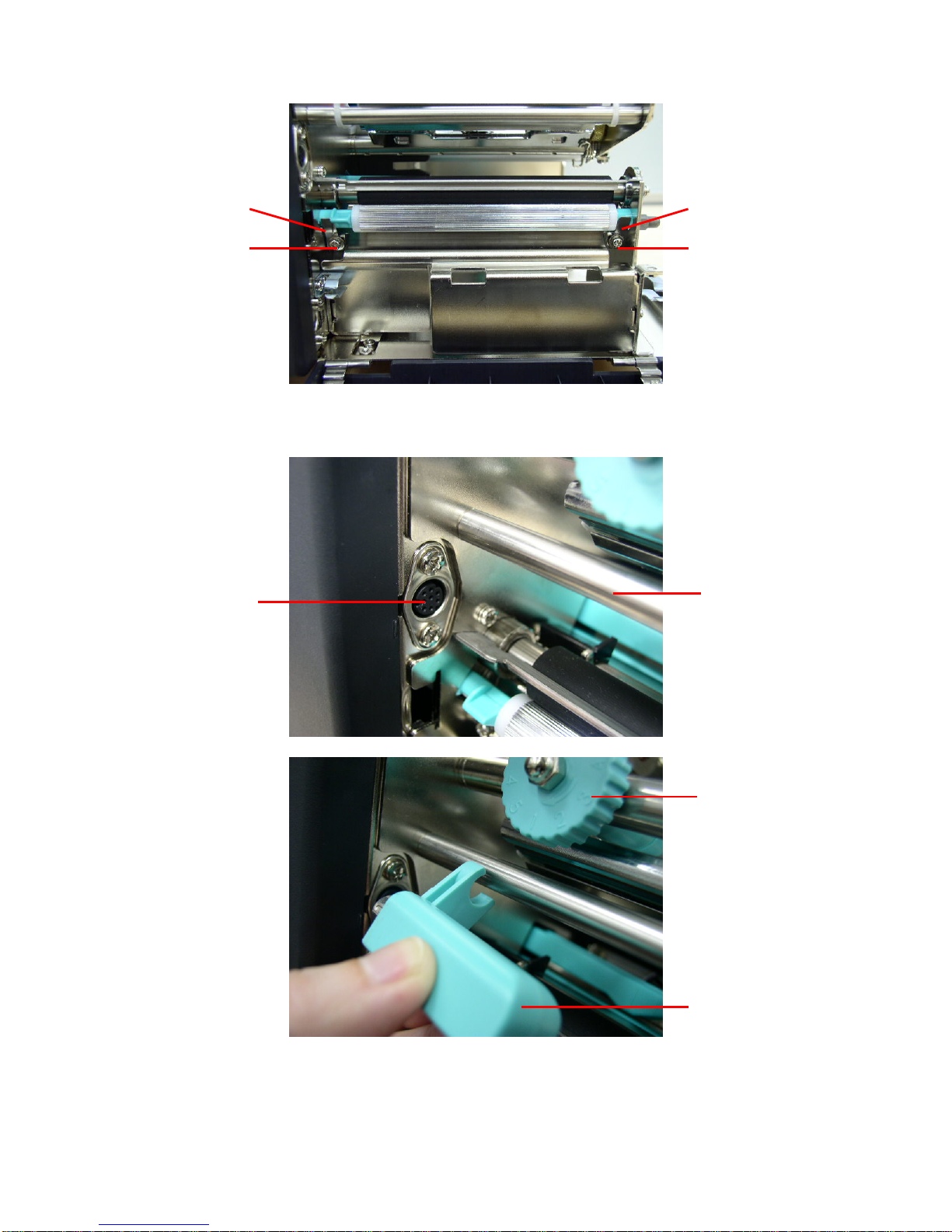
5.
Hook the peel-off sensor on the bar which is near by the peel off sensor
connector. Plug in the peel-off sensor assembly to the connector.
Peel-off sensor assembly
Bar
Peel-off sensor
assembly connector
Screw
Screw
Print head pressure
adjustment knob
Right side leaf spring
Left side leaf spring
Page 19
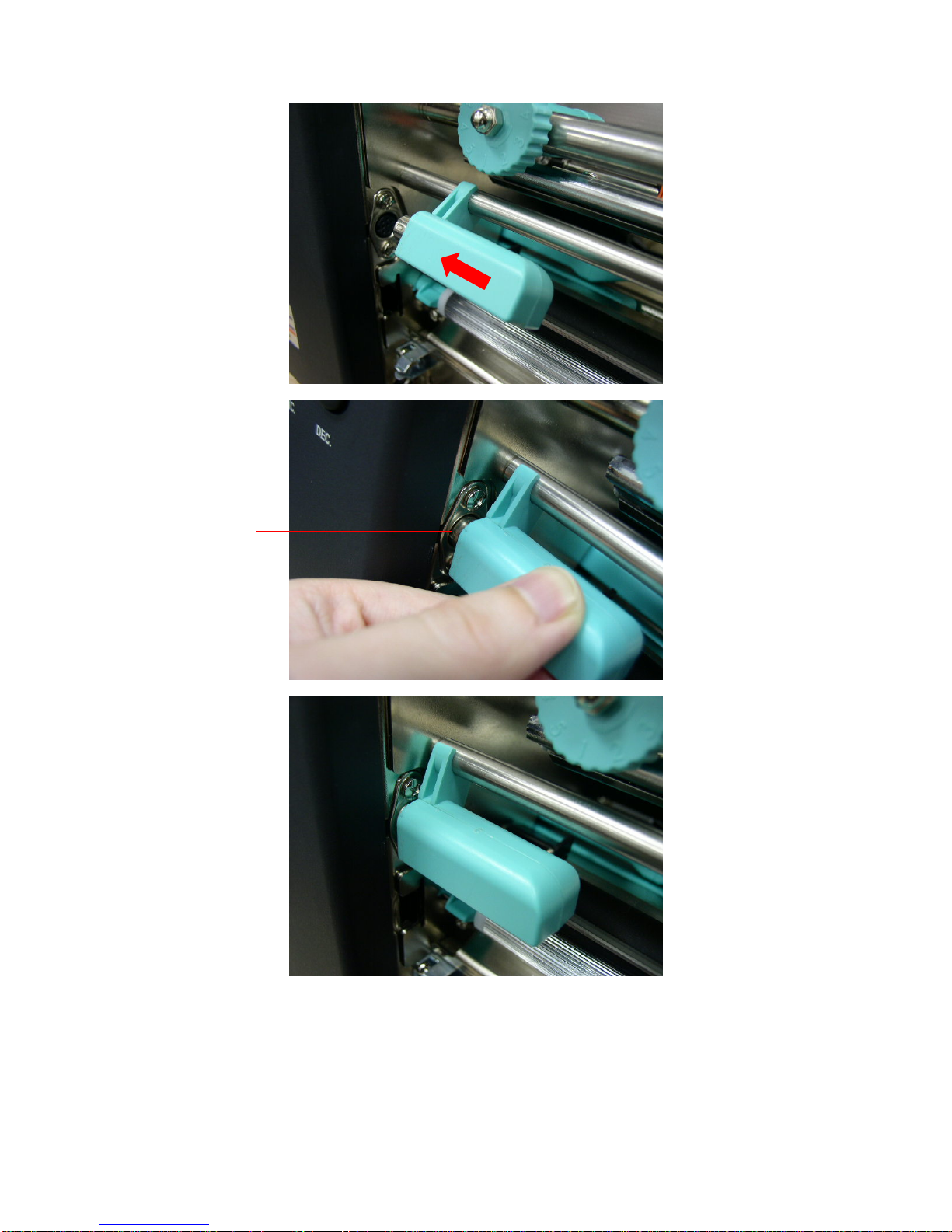
15
Plug in the peel-off
sensor assembly to
the connector.
Page 20
16
3.6 Loading Label For Peel-off Mode
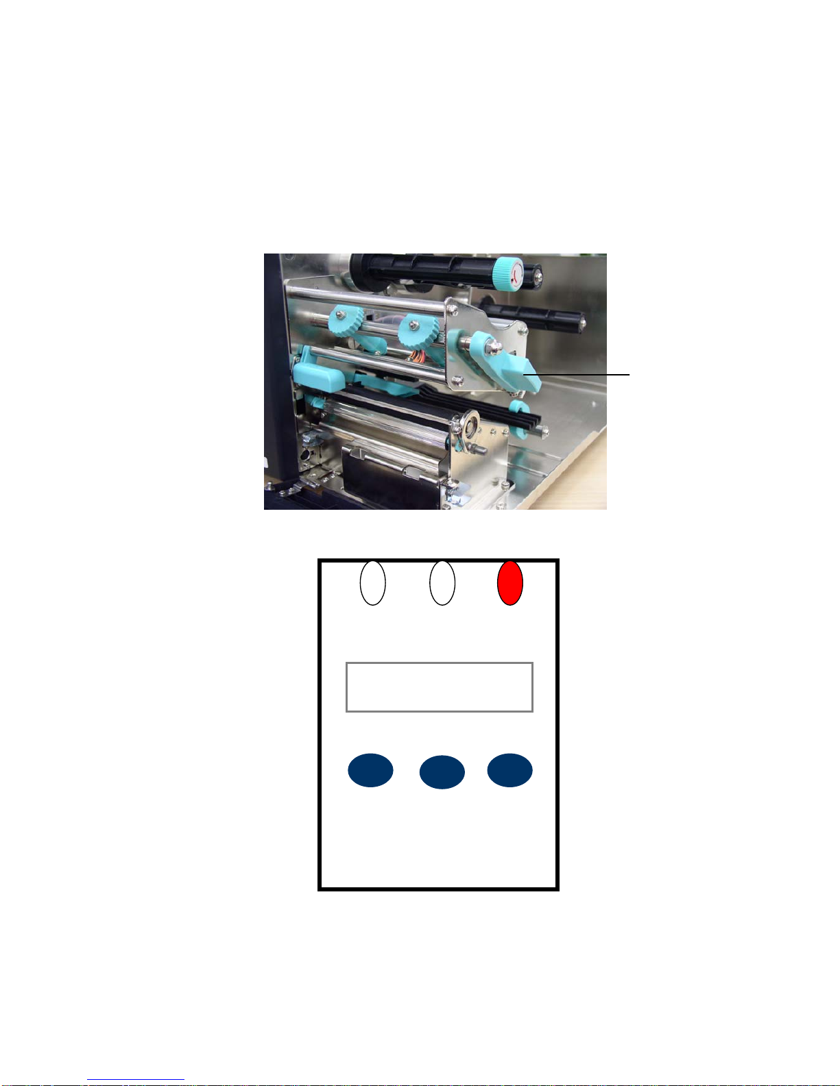
1. Open the Print Head Lift Lever. The message “CARRIAGE OPEN” will be
shown on the LCD screen, and the RED LED is on. The LCD panel shown
as below.
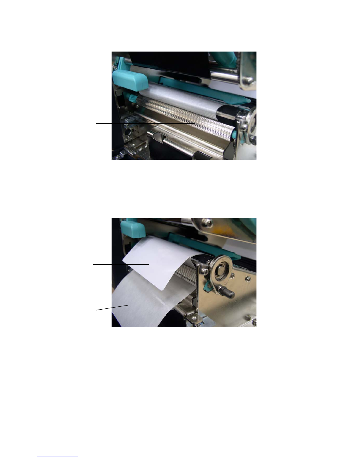
2. Remove the first one label from the liner. Insert the liner into the gap
Print Head Lift
Lever
ERRORON-LINE
MENU
CARRIAGE OPEN
Fwd. Rev.
POWER
PAUSE
FEED
SELECT
POWER
EXE./INC.
DEC.
Page 21
17
between Platen and Pee-off roller.
3. Press the button (MENU, SELECT) under the message “Fwd.” to feed the
label forward a little bit. Press the button (PAUSE, EXE./INC.) under the
message “Rev.” to reverse the label if it is necessary for adjusting the label.
Pull the liner outward tightly. Close the Print Head Lift Lever.
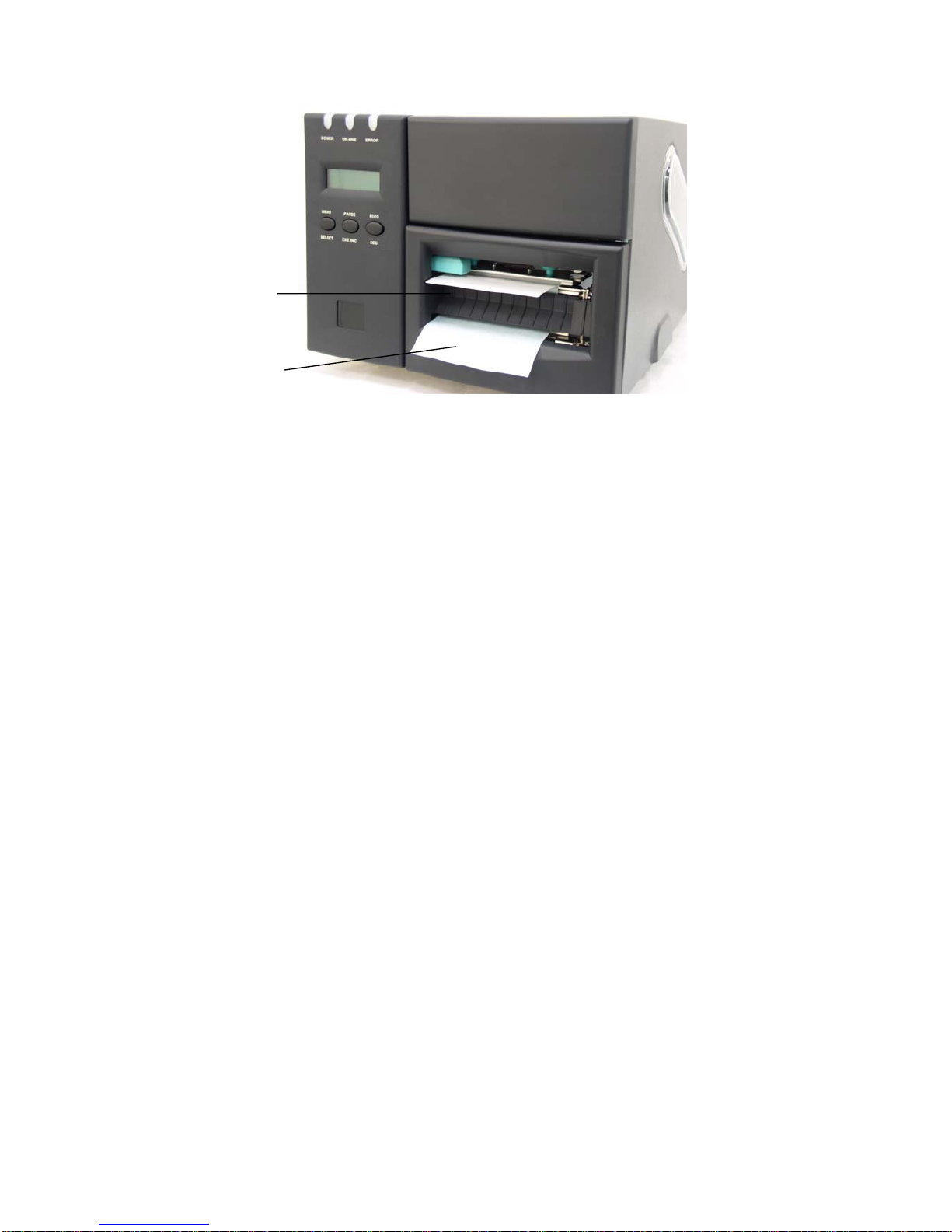
4. Close the lower front panel. Pull the label through the Peel-off panel upper
opening; pull the liner through the Peel-off panel upper opening.
Label
Liner
Peel-off roller
Liner
Page 22
18
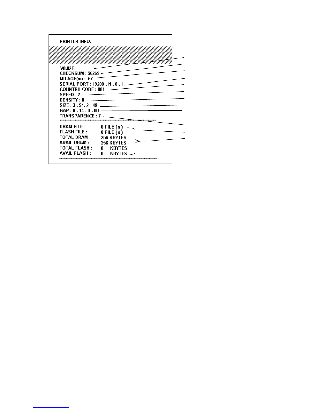
3.7 Self-test
To initiate the self-test mode, depress the MENU button. Press MENU button to
scroll the cursor to Printer test. Press EXE button to enter the submenu and
press MENU button to “Printer Config”. item. Press EXE button to print printer
internal setting. In self-test, a check pattern is used to check the performance of
the thermal print head. Following the check pattern, the printer prints internal
settings as listed below:
1. Firmware version
2. Check sum
3. Serial port setting
4. Code page setting
5. Country code setting
6. Print speed setting
7. Print density setting
8. Label size setting
9. Gap (Bline) width and offset setting
10. Backing paper transparence
11. File list
12. Memory available
Label
Liner
Page 23
19
Figure 10. Printout of self-test
Note:
1. The physical flash memory for RoHS compliant version is 2MB Flash and
2MB DRAM.
2. System occupies 960 KB in Flash memory so total flash memory space
for user downloading is 1088 KB
3. System occupies 1792 KB in DRAM so total DRAM memory space for
user downloading is 256 KB
3.8 Dump Mode
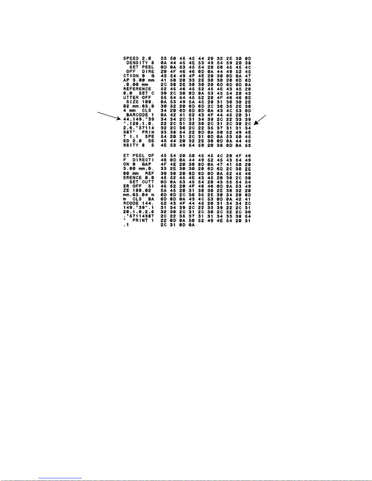
To enter dump mode, press MENU button to scroll the cursor to “Printer Test”
then press EXE button to enter the submenu. Press MENU button to scroll dump
mode. Press EXE button to select line dump mode or page dump mode. Press
MENU button to select EXIT to enter dump mode. In this mode, any character
sent from the host computer will be printed in two columns, as shown in Figure
10.
The characters received will be printed in two columns as below.
On the left side of the paper are the characters received, and on the right side
are the corresponding hexadecimal values. This is very helpful to users for the
verification of programming commands or debugging of printer programs. Reset
the printer by pressing the FEED button.
Print head check pattern
Firmware version
Firmware checksum
Printed mileage (meter)
Serial port configuration
Country code
Print speed (inch/sec)
Print density
Label size (inch)
Gap distance (inch)
Gap/black mark sensor sensitivity
Backing paper transparence
Numbers of download files
Total & available memory space
Page 24
20
Figure 11. Printout of dump mode
ASCII Data
Hex decimal data
related to left
column of ASCII
data
Page 25

21
4. USING TTP-246M/344M
4.1 Power-on Utilities
There are two power-on utilities to calibrate sensor and initialize TTP-246M/344M
hardware. These utilities are activated by pressing the PAUSE button, PAUSE
and FEED buttons and turning on the printer power simultaneously. The utilities
are listed as below :
1. Gap/black mark sensor calibration
2. Printer initialization
4.1.1 Gap/Black Mark Sensor Calibration Utility
This utility is used to calibrate the sensitivity of the gap/black mark sensor. The
gap/black mark sensor must be calibrated whenever changing the label media
or executing printer initialization.
Please follow the steps below to calibrate the gap sensor.
1. Install the ribbon and label roll as the above-mentioned procedures, and
engage the print head lift lever.
2. Turn off printer power.
3. Press PAUSE key and then turning on printer power. Release the PAUSE
key when “GAP/BLINE sensor calibrating….” Message is shown on the LCD
display. The printer will calibrate the gap/black mark sensor automatically.
Page 26
22
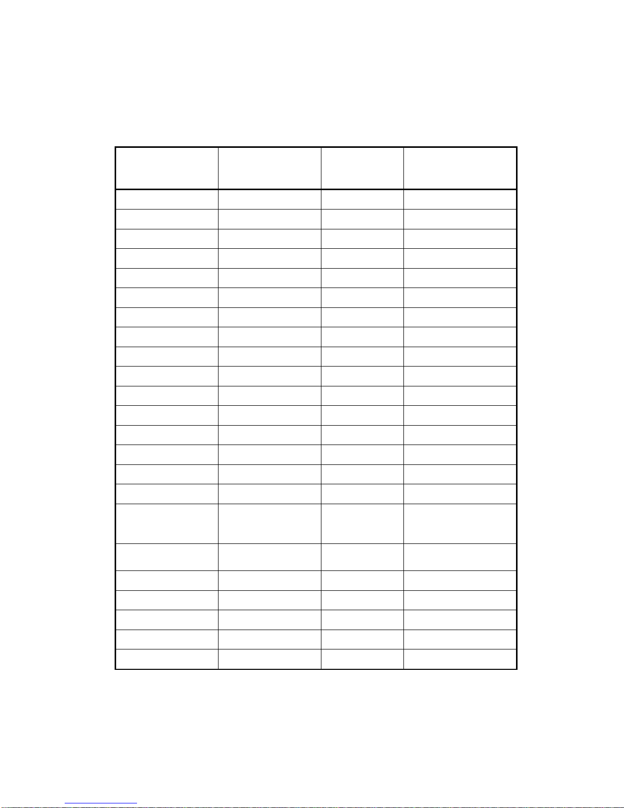
4.1.2 Printer Initialization
Printer Initialization will restore printer settings to defaults.
Default settings are listed as below.
Item Default Value
Cleared by
Initialization
Property Saved
when Turning off
Power
Mileage N/A No Yes
Check Sum N/A No Yes
Serial Port 9600,n,8,1 Yes Yes
Code Page 437 Yes Yes
Country Code 001 Yes Yes
Tear Mode On Yes Yes
Peel Mode Off Yes Yes
Cutter Mode Off Yes Yes
Offset 0 Yes Yes
Reference Point 0,0 Yes Yes
Print Direction 1 Yes Yes
Speed 4 inch/sec Yes Yes
Density 07 Yes Yes
Label Size 4 x 2.5” Yes Yes
Gap/Bline Sensor Gap Sensor Yes Yes
Gap(Bline) 0.12” (3 mm) Yes Yes
Transparency
Will be reset. Need
to re-calibrate the
gap sensor
Yes Yes
Ribbon Sensor
Sensitivity
1 Yes Yes
LCD Language English Yes Yes
Aux. LED Off Yes Yes
Aux. Buzzer Off Yes Yes
Download Files N/A No Yes
RTC N/A No No
Please follow the steps below to initialize the printer:
1. Turn off the printer power.
Page 27

23
2. Hold down the PAUSE and FEED buttons and turn on the printer power.
3. Do not release the buttons until the Red LED flash in turn.
Note1: Printing method (thermal transfer or thermal direct printing ) will be
set automatically at the activation of printer power.
Note2: When printer initialization is done, please calibrate the gap sensor
again.
Page 28

24
4.2 Troubleshooting Guide
The following guide lists the most common problems that may be encountered
when operating this bar code printer. If the printer still does not function after all
suggested solutions have been invoked, please contact the Customer Service
Department of your purchased reseller or distributor for assistance
Phenomenon Reasons Solutions
No ribbon
1. Running out of ribbon
2. The ribbon is installed
incorrectly.
3. The ribbon sensor is not
been well calibrated.
1. Supply a new ribbon roll.
2. Please refer to the steps in
section 3.2 Ribbon
Installation to reinstall the
ribbon.
3. Please calibrate the ribbon
sensor
No paper
1. Running out of label
2. The label is installed
incorrectly.
3. The moveable gap/black
mark sensor is not placed in
the proper location.
1. Supply a new label roll.
2. Please refer to the steps in
section 3.3 Label Roll
Installation to reinstall the
label roll.
3. Please move the sensor to the
proper location.
Poor printing
quality
1. Dirt is accumulated on the
print head.
2. The density setting is not
set properly
3. Ribbon and media are
incompatible.
4. The pressure of print head
is not set properly
1. Please refer to the steps in the
section 5.1 Print Head
Cleaning to clear the print
head.
2. Adjust the print density and
speed.
3. Change proper ribbon or
proper label roll.
4. Adjust the print head pressure
adjustment knob.
Power indicator
does not
illuminate
1. The power cord is not
properly connected.
2. The voltage setting of power
supply in the rear of printer is
set incorrectly.
1. Please check whether the
power cord is well connected
between printer and outlet.
2. Please set the voltage setting
of power supply at the rear of
printer to the proper voltage.
Paper jam
1. The label size is not set
properly.
2. Labels may be stuck in side
print mechanism.
1. a. Reset the label size.
b. Re-calibrate the
gap/black mark sensor.
2. Remove the stuck label.
Carriage open
The printer carriage is open. Please close the print carriage.
Page 29

25
Memory full
(FLASH / DRAM)
The space of FLASH/DRAM is
full.
Delete unused files in the
FLASH/DRAM.
Maximum 50 files saved in DRAM.
Maximum 100 files saved in Flash
Files.
No printout
printing through
serial port
1. The serial port setting is not
consistent between host and
printer.
2. The serial port cable pin
configuration is not pin to pin
assignment.
1. Please reset the serial port
setting.
2. Please replace the cable with
pin to pin assignment.
Page 30

26
5. PRINTER CLEANING
The printer should be cleaned regularly to retain high quality and optimum
performance.
5.1 Print Head Cleaning
1. Always turn off the printer before cleaning the print head. Allow the printhead
to cool for a minimum of one minute.
2. Open the printer cover.
3. Remove the screw by the side of the print head lift lever.
4. Open the printer print head lift lever.
5. Remove the media and ribbon. (If loaded)
6. Use a cotton swab and 100% ethanol to clean the print head surface.
7. Do not close the print head until the alcohol volatilizing.
8. Close the printer cover.
Note:
* Do not touch printer head by hand. If you touch it careless, please use ethanol
to clean it.
*It’s industry alcohol. Please do not use regular alcohol, which may damage the
printer head.
5.2 Printer Cover Cleaning
1. Switch off and unplug the printer.
2. Using a lint-free cloth soaked in the water or mild detergent, wipe the printer
cover light.
※ Do not use harsh or abrasive cloth and solvent.
5.3 Internal Parts Cleaning
1. Switch off and unplug the printer.
2. Open the printer right side cover.
3. Remove the media and ribbon (If loaded).
4. Open the printer print head lift lever.
5. Using a soft cloth soaked in the alcohol or mild detergent to wipe the internal
parts.
6. The rubber roller should be clean by cloth soaked in water.
7. Install the ribbon and label, close the print head lift lever.
8. Close the printer right side cover.
Page 31

27
APPENDIX LCD Control Panel Operation Map
1. Print Setup
0~999 (*0)
Auto. Ribbon
Manual Bline
Auto Bline
2. Sensor Calib.
Speed
Auto. Gap
Cutter Batch* Tear Mode Peel On
Manual Ribbon
Cutter On
Manual Gap
Exit
Reference Y
Reference X
Offset
Density
Direction
Lang.
3. System Setup
簡體中文繁體中文
* English
日本語
Code Page
SPA ITA DAN
FREGER
SWI
SWE
850* 437 852
860863865
BRIUSA
2 "/sec * 3"/sec 4"/sec
0~15 (*7)
0 * 1
0~999 (*0)
0~999 (*0)
Note:
1. Defaults are marked with asterisk (*)
2. The parameter of shaded area can be accessed by
pressing the INC. or DEC. key to set the value.
Exit
Page 32

28
Country
* 87
* NoneParity
Data Bit
OddEven
Baud
2* 1Stop Bit(s)
57600 56000 38400
* 19200960048002400
Restore Defaults
Exit
Avail. Memory
File List
4. File Mngment
DRAM:
512KB free
PAUSE: Del. All
FEED: Exit
Delete File(s)
Exit
* 001 002 003 031 032
033034036038039
041 042 046045044
061 055 047048049
351 358
Self Test
5. Printer Test
Rotate Cutter
* Dump Mode Off Dump Mode On
Exit
MENU: Fwd.
PAUSE: Rev.
3. System Setup
FLASH:
1000KB free
Mileage Info.
Mileage:(m)
000000000
Lables:(pcs)
000000000
Page 33

Headquarters / Factory
Taipei Office
No. 35, Sec. 2, Ligong 1st Rd., Wujie Town 11F, No. 205, Sec. 3, Beishin Rd., Shindian City,
, I-Lan County
268, Taiwan, R.O.C. Taipei 231, Taiwan, R.O.C.
TEL: +886-3-990-6677
TEL: +886-2-8913-1308
FAX: +886-3-990-5577
FAX: +886-2-8913-1808
Web site: w
ww.tscprinters.com
E-mail: [email protected]
TSC Auto ID Technology Co., Ltd.
 Loading...