

Page 1
Quick Installation Guide
1. Printer Installation
Place this printer on a flat stable surface and make sure the power switch is turned off.
1. Connect the printer to the host computer with a Parallel Centronics, Serial RS-232C or USB cable.
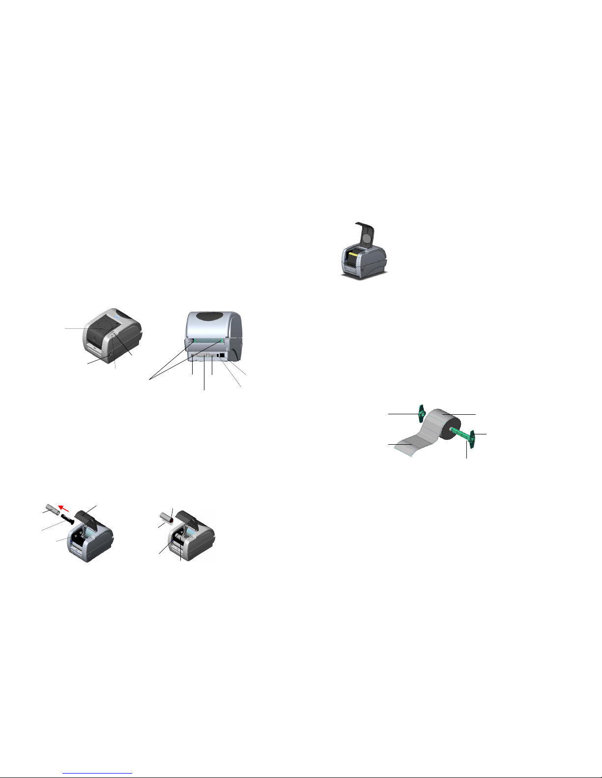
2. Plug the power cord into the power jack connector at the rear of the printer, then plug the power cord into a
properly grounded outlet (refer to figure 2).
2. Loading the Ribbon
Note: The printer automatically detects if a ribbon is installed after power on and will switch to thermal transfer or
direct thermal printing mode. If the printer does not detect a ribbon (direct thermal mode), the motor that drives the
ribbon spindles will be turned off. Make sure both the ribbon access window and the printer top cover are closed
when powering the printer up.
1. Push down on the ribbon access window to unlock and open the cover (refer to figure 3).
2. Place a paper core on a ribbon rewind spindle.
3. Mount the ribbon rewind paper core on the front hubs.
4. Install a ribbon on the ribbon supply spindle.
5. Mount the ribbon supply spindle on the rear hubs (refer to figure 4).
6. Pull the ribbon from the ribbon supply spindle and cross the print head, stick the ribbon onto the Ribbon
Rewind Paper Core (refer to figure 5).
7. Attach the ribbon leader to the ribbon rewind paper core.
8. Rotate the ribbon rewind paper core until the ribbon leader is thoroughly, firmly encompassed by the black
section of the ribbon.
9. Close the ribbon access window.
3. Loading the Label
1. Insert a 1” label spindle into a paper roll ( * If your paper core is 1 inch, remove the 1.5” core adapter from the
fixed tab).
2. Open the printer’s top cover by releasing the green Top cover open levers located on each side of the printer
and lifting the top cover. A Top Cover support at the rear of the printer will hold the printer top cover open.
3. Place a roll of paper onto the center of the paper roll mount (refer to figure 7).
4. Feed the paper, printing side face up, through the Teflon bar and the paper guide and pass over the platen.
5. Adjust the green center-biased paper guides in or out so they are slightly touch the edges of the label backing.
6. To close the printer top cover, lift the cover slightly and pull the bottom of the Top Cover support forward
toward the front of the printer. Close the printer top cover slowly and make sure the cover locks latch securely.
Note: failure to securely close and lock the cover will result in poor print quality.
Centronics
RS-232
Power Jack
Power Switch
Ribbon Access
Window
Feed Button
Ribbon Rewind
Spindle
Paper Core
Rear Paper Guide
LED Indicator
Ribbon Access
Window
Front Hub
Ribbon
Leader
Rear Hub
Paper Roll
1” label spindle
Printing Side
Face Up
1.5” Core
Adapter*
USB
Figure 1
Figure 2
Figure 3
Figure 4
Figure 6
Fixed Tab
Ribbon Supply Spindle
Ribbon Rewind Paper Core
Top Cover Open
Lever
Page 1 of 2
Figure 5
Page 2
4. Button Functions
This printer has one button and one three-color LED indicator. By indicating the LED with different color and
pressing the button, printer can feed labels, pause the printing job, select and calibrate the media sensor, print
printer self-test report, reset printer to defaults (initialization). Please refer to the button operation below for different
functions.
Regular button function
1. Feed labels
When the printer is ready, press the button to feed one label to the beginning of next label.
2. Pause the printing job
When the printer is printing, press the button to pause a printing job. When the printer is paused the LED is green
with blinking. Press the button again to continue the printing job.
Power on utilities
There are six power-on utilities to set up and test printer hardware. These utilities are activated by pressing FEED
button then turning on the printer power simultaneously and release the button at different color of LED.
Please follow the steps below for different power-on utilities.
1. Turn off the power switch.
2. Hold on the button then turn on the power switch.
3. Release the button when LED indicates with different color for different functions.
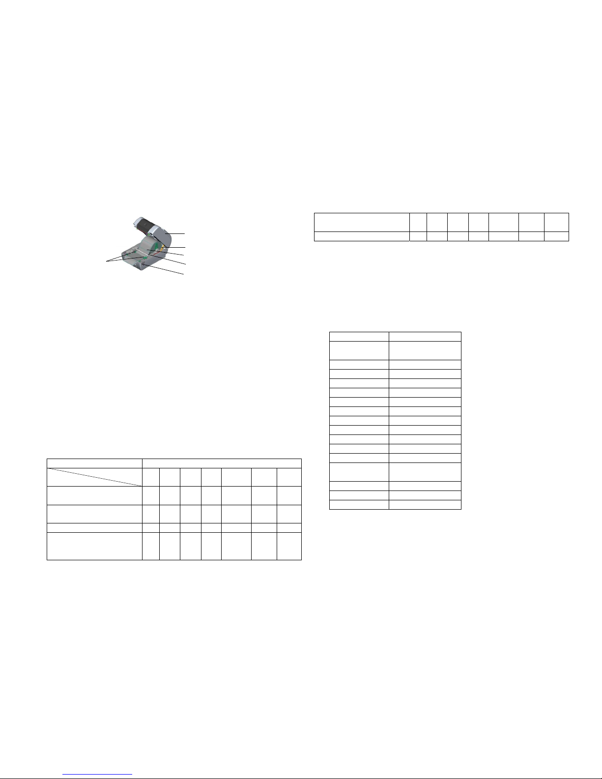
Power on utilities The LED color will be changed as following pattern:
LED color
Functions
Amber Red
(5 blinks)
Amber
(5 blinks)
Green
(5 blinks)
Green/Amber
(5 blinks)
Red/Amber
(5 blinks)
Solid green
1. Ribbon Sensor Calibration and Gap /
black mark sensor calibration
Release
2. Gap / black mark sensor calibration,
Self-test and enter dump mode
Release
3. Printer initialization
Release
4. Set black mark sensor as media
sensor and calibrate the black mark
sensor
Release
5. Set gap sensor as media sensor and
calibrate the gap sensor
Release
6. Skip AUTO.BAS
Release
Note:
1. Please select gap or black mark sensor by GAP or BLINE command or by power-on utility function 4 or 5
prior to calibrate the sensor. For more information about GAP and BLINE command, please refer to
TSPL2 programming manual.
2. After dump mode, turn off / on the power to resume printer for normal printing.
3. Always do gap/black mark sensor calibration after printer initialization or after changing different type of
media.
4. Printer default settings are listed as below:
Item Settings
Speed 127 mm/sec (5 ips) (203 DPI)
76 mm/sec (3 ips) (300 DPI)
Density 7
Label Width 4.25” (108.0 mm)
Label Height 2.5” (63.4 mm)
Sensor Type Gap sensor
Gap Setting 0.12” (3.0 mm)
Print Direction 0
Reference Point 0,0 (upper left corner)
Offset 0
Tear Mode On
Peel off Mode Off
Cutter Mode Off
Serial Port Settings
9600 bps, none parity,
8 data bits, 1 stop bit.
Code Page 850
Country Code 001
Clear Flash Memory No
Paper Guide
Top Cover Open Lever
Top Cover Support
Paper Roll Mount
Teflon Bar
Printer Top Cover
Figure 7
Page 2 of 2
P/N:39-0000112-10LF
 Loading...