

Page 1

TTP 243 Plus/ 243E Plus/ 342 Plus
Service Manual
THERMAL TRANSFER / DIRECT THERMAL
BAR CODE PRINTER
Page 2

i
TTP-243 Plus/ 243E Plus/
342 Plus Bar Code Printer
Table of Contents
1. FUNDAMENTALS ABOUT THE SYSTEM .................................................................. 1
1.1 Features of the TTP-243 Series ................................................................................. 1
1.2 Model Naming Syntax ................................................................................................. 1
1.3 Overview .................................................................................................................... 2
1.3.1 Front View ........................................................................................................... 2
1.3.2 Rear View ........................................................................................................... 3
1.4 Basic Specifications .................................................................................................... 4
1.5 Effective Print Area ..................................................................................................... 6
1.6 Available Bar Codes ................................................................................................... 6
1.7 Various Sensors ......................................................................................................... 7
2. SUPPLY SPECIFICATIONS ............................................................................................. 9
2.1 Types of Paper ........................................................................................................... 9
2.2 Specifications ................................................................ ............................................. 9
2.3 Ribbon Sizes and Shapes ........................................................................................ 11
3. ELECTRONICS .............................................................................................................. 12
3.1 Circuit Description .................................................................................................... 12
3.2 MCU Pin Description ................................................................ ................................ 14
3.3 Reset Circuit ............................................................................................................. 16
3.4 Memory System........................................................................................................ 16
3.5 Sensor&Key ............................................................................................................. 17
3.6 Real-Time Clock Circuit ............................................................................................ 18
3.7 Decode Circuit .......................................................................................................... 19
3.8 Thermal Head Drive/ Protection and History Control Circuit ..................................... 21
3.9 24V/5V Converter Circuit .......................................................................................... 22
3.10 Stepping Motor And DC Motor Driver/ Protection Circuit ........................................ 23
3.11 Communication (Serial & Parallel Port) Circuit........................................................ 24
3.12 Cutter Drive Circuit ................................................................................................. 25
3.13 Cutter & Peel Translate Board ................................................................................ 25
3.14 Mainboard Replacement ......................................................................................... 26
Page 3

ii
TTP-243 Plus/ 243E Plus/
342 Plus Bar Code Printer
3.15 Cutter, DC Motor, Stepping Motor Driver IC Replacement ...................................... 30
4. MECHANISM .................................................................................................................. 31
4.1 Cutter Installation ..................................................................................................... 31
4.2 Print Head Replacement .......................................................................................... 32
4.3 DC Motor Replacement ............................................................................................ 34
4.4 Ribbon Rewind Spindle Encoder Replacement ........................................................ 34
4.5 Felt Fabric Replacement .......................................................................................... 36
4.6 Stepping Motor Replacement ................................................................................... 38
4.7 Black Mark Sensor / Gap Sensor (Receiver) Replacement ...................................... 39
4.8 Ribbon Sensor (Receiver) Replacement ................................................................... 39
4.9 Ribbon Sensor (Transmitter) / Gap Sensor (Transmitter) Replacement ................... 42
4.10 Platen Replacement ............................................................................................... 43
5. TROUBLE SHOOTING ................................................................................................... 46
5.1 Error Messages ........................................................................................................ 46
5.2 Trouble Shooting ...................................................................................................... 47
5.3 Calibrate the Gap Register ....................................................................................... 48
5.4 Self-test .................................................................................................................... 48
5.5 Ram Clear ................................................................................................................ 48
5.6 Diagnosis Operation Procedure ................................ ................................................ 48
5.7 Testing Sensors ....................................................................................................... 49
5.8 Cleaning the Print Head ........................................................................................... 51
Page 4

1
TTP-243 Plus/ 243E Plus/
342 Plus Bar Code Printer
1. FUNDAMENTALS ABOUT THE SYSTEM
1.1 Features of the TTP-243 Series
1. This bar code printer prints bar codes, characters, logos, on various types of labels and tickets
by direct thermal or thermal transfer printing.
2 This printer adopts a “BASIC-like” high level programming language to help users programme
the desired label forms with ease.
3. This bar code printer can be connected to a personal computer or an optional LCD keyboard
to execute the programs downloaded in the printer‟s memory. The printer is equipped with the
following standard devices: black mark sensor, peel off module and real time clock.
4. This bar code printer provides a selection of optional features, including cutter module,
memory module, portable LCD keyboard, etc.
5. The user friendly labeling software package is bundled with printer.
1.2 Model Naming Syntax
T T P – 2 4 3
(1) (2) (3) (4)
(1) Print method:
TTP – Thermal Transfer Printing
TDP – Thermal Direct Printing
(2) Resolution of print head (DPI)
(3) Maximum print width (Inch)
(4) Maximum print speed (Inch/Sec)
Page 5

2
TTP-243 Plus/ 243E Plus/
342 Plus Bar Code Printer
1.3 Overview
1.3.1 Front View
Fig. 1.1 Front View
Note: The one difference between TTP model and TDP model is the ribbon mechanism.
Front Panel
Cover Release Button
Top Cover
Operation Panel
Page 6

3
TTP-243 Plus/ 243E Plus/
342 Plus Bar Code Printer
1.3.2 Rear View
Fig. 1.2 Rear view
DC Power Jack
Centronics Interface
Label
Entrance
(External
Mount Use)
Power
Switch
Page 7

4
TTP-243 Plus/ 243E Plus/
342 Plus Bar Code Printer
1.4 Basic Specifications
Thermal transfer and direct thermal printing
High dot density printing (203 dots/inch)
Selectable print speeds at 1.5”, 2.0” or 3.0” per second
Supports parallel and serial interface
Maximum media width up to 4.4” (114 mm)
Adjustable label edge guide
International character sets
Print area:TTP-243 Plus/243E Plus:4.09” W x 39” L;TTP-342 Plus:4.09”W x 18”L (without
any file downloaded in the printer memory)
User selectable bar code ratios and heights
Prints on labels or tickets
Equipped with black mark sensor
Equipped with Real Time Clock (243 Plus only)
Comes with self-peeling function (243 Plus only)
Buzzer provided to warn of possible errors (243 Plus only)
Label stock and thermal transfer ribbon are easy to install
Internal label print counter
Self test and hex dump mode
Downloadable fonts from label design software
Electronics/Communication Specifications
Electrical
CPU: Hitachi SH2 7040
TPH: ROHM 4” KF-2004-GC17B
Stepping Motor: Mitsumi
DC Motor: DC24V
Memory:
─DRAM: 2 Mb
─Flash: 2 Mb
Adapter 100~240VAC10%, 50~60Hz
Regulations: CE, FCC,TÜ V-GS
Communications Interface:
Serial port: RS-232C (DB-9) at 2400, 4800, 9600 or 19200 baud rate
─Word Length: 7 or 8 data bits, 1 or 2 stop bits, selectable parity
─Handshaking: XON/XOFF and DSR/DTR
Parallel port: Standard parallel interface
Input Buffer: 60KB
RS-232 Interface Pin Configuration:
Page 8

5
TTP-243 Plus/ 243E Plus/
342 Plus Bar Code Printer
Host Function
9 Pin
25 Pin
9 Pin
Printer Function
1 +5V
RxD
2 3 2 TxD
TxD
3 2 3 RxD
DTR
4
20 4
DSR
GND
5 7 5 GND
DSR
6 6 6 RDY
RTS
7 4 7 N/C
CTS
8 5 8 RDY
9
+5V
Page 9

6
TTP-243 Plus/ 243E Plus/
342 Plus Bar Code Printer
1.5 Effective Print Area
Label/Ticket Length
12mm~2286mm
Effective Print
Length
10mm~2284mm
Label/Ticket Width
25mm~103mm
Effective Print Width
23mm~101mm
No Print Area
1mm
1.6 Available Bar Codes
Code 39
Code 93
Code 128 UCC
Code 128, Subsets A, B, and C
Codabar
Interleaved 2 of 5
EAN-8, EAN-13, EAN-128
UPC-A, UPC-E
EAN and UPC with 2 or 5 digits add-on
UPC Shipping container code
Postnet
Maxicode
PDF-417
DataMatrix
Page 10

7
TTP-243 Plus/ 243E Plus/
342 Plus Bar Code Printer
1.7 Various Sensors
Feed Gap Sensor
The feed gap sensor detects a label gap to locate the starting print position of the next
label. The sensor is mounted 4 mm off the center line of the main mechanism.
.
In case of Label
Black Mark Sensor
The black mark sensor locates the position of label by emitting infrared rays onto the
black mark at the back of the ticket. The sensor is mounted 5.75 mm off the center line
of the ticket roll width on the mechanism.
Page 11

8
TTP-243 Plus/ 243E Plus/
342 Plus Bar Code Printer
In case of Ticket
The default sensor position is (1) as shown on the figure below. To change to the (2)
position, the customer should notify the manufacturer in advance. There can be only
one position for the sensor. Once the sensor position is agreed upon, it can not be
changed afterwards.
Ribbon End Sensor
The sensor detects the end portion of the ribbon. The ribbon end must be transparent.
Label End Sensor
The sensor detects the end portion of the label.
Peel off Sensor
The sensor detects the backing paper of a label.
Ribbon encoder
The encoder is used to detect if the ribbon is broken.
Page 12

9
TTP-243 Plus/ 243E Plus/
342 Plus Bar Code Printer
2. SUPPLY SPECIFICATIONS
2.1 Types of Paper
Two types of media are available for TTP-243: label and ticket.
In TTP-243, there are two types of sensors for paper: gap sensor and black mark
sensor.
Label and ticket can be further classified into direct thermal type or thermal transfer
type.
2.2 Specifications
Items
Label
Paper Width
Max.114mm
Min. 25mm
Length (Pitch)
12~2286mm
Paper
Thickness
0.20 mm
Paper Weight
Max 240 g/m2
Max. Roll
Diameter
(1” core)
Inner roll diameter. Max 4.3” (110mm)
External roll diameter. Max 8.4”
(214mm)
Roll Up Method
Print surface wound outside as
standard
Paper Core ID.
25.7±0.3mm
Note:
(1). The width and thickness quoted above are said of the label plus its backing paper.
(2). Likewise, the approval of label entails that of its backing paper.
(3). In the peel off mode, the minimum pitch is 35mm.
(4). In the cutter mode, it is required the paper be wound outside. Otherwise, paper jam
tends to result.
(5). In the cutter mode, the paper thickness is 0.2 mm at maximum, and the paper weight is
100 g/m2 at maximum.
(6). Paper shape is as shown on next page.
(7) Tag is 0.2mm in thickness, and is less than 100g/m2 in weight.
Page 13

10
TTP-243 Plus/ 243E Plus/
342 Plus Bar Code Printer
Page 14

11
TTP-243 Plus/ 243E Plus/
342 Plus Bar Code Printer
2.3 Ribbon Sizes and Shapes
Item
Specifications
Ribbon shape
Spool type
Ribbon width
Max. 110mm
Min. 40mm
Ribbon winding width
Max. 110mm
Min. 40mm
Leading tape
Polyester film, 3355mm long
End tape
Polyester film (transparent), 2505mm
long
Max. ribbon OD.
67mm
Winding method
Ink surface to be wound outside
Note: The maximum length of ribbon depends on its thickness and core outside diameter.
The formula below defines the correlation between ribbon roll length and ribbon core
diameter.
t4
)d(D
= L
22
, where
L = Ribbon length
D = Max. roll diameter
d = Ribbon core outside diameter
t = Ribbon thickness
Page 15

12
TTP-243 Plus/ 243E Plus/
342 Plus Bar Code Printer
3. ELECTRONICS
3.1 Circuit Description
Fig. 3.1 MCU Circuit Diagram
The above is the MCU circuit diagram.
The main board includes seven system blocks:
A: MCU & Decode System
B. Memory System
C. Motor System (stepping motor, DC motor and cutter block)
D. Print head System
E. Communication System (serial & parallel port block)
F. Sensor & Key System
Page 16

13
TTP-243 Plus/ 243E Plus/
342 Plus Bar Code Printer
G. Power System
The figure below shows the PCB system area.
Motor
System
Communication Port
Real Time
Clock
Memory
Decoder
System
Print
Head
Cutter
Memory
System
External
Memory
Connector
Power
Page 17

14
TTP-243 Plus/ 243E Plus/
342 Plus Bar Code Printer
3.2 MCU Pin Description
Port
I/O
Initial
High
Low
Function
Instruction
PA0
I
Pull Up
RXD0
RXD for RS232
PA1 O
TXD0
TXD for RS232
PA2
I
Pull Up
PA2
RTS for RS232
PA3 O
PA3
CTS for RS232
PA4 O
TXD1
DI for TPH
PA5 O
SCK1
CLK for TPH
PA6
O
Pull Up
Active
/CS2
/CS2
PA7
O
Pull Up
Active
/CS3
/CS3
PA8 I Active
IRQ2
Power down
PA9
I
Pull Up
Active
IRQ3
USB_INT
PA10
O
Pull Up
Active
/CS0
/CS0
PA11
O
Pull Up
Active
/CS1
/CS1
PA12 O
/WRL
/WRL
PA13 O
/WRH
No use
PA14 O
/RD
/RD
PA15
O
Pull Up
Enable
PA15
/LAT for TPH
PB0 O
A16
A16
PB1 O
A17
A17
PB2 O
/RAS
/RAS
PB3 O
/CASL
/CASL
PB4 O
/CASH
/CASH
PB5 O
RDWR
RDWR
PB6 O
A18
A18
PB7 O
A19
A19
PB8 O
A20
A20
PB9 O
A21
A21
PC0~PC15
O
A0~A15
A0~A15
PD0~PD15
I/O
D0~D15
D0~D15
PE0 O PWM
Enable
TIOC0A
GAP LEVEL
PE1
I
Pull Up
PE1
KEY3
PE2
I
Pull Up
Enable
PE2
CASE OPEN
PE3
I
Pull Up
Enable
PE3
/STTOBE for Centronic port
PE4 O PWM
Enable
TIOC1A
DCM for DC motor enable
PE5
O
Pull Up
Enable
PE5
STB1 for TPH
PE6
I
Pull Up
Enable
PE6
DC SENS for DC sensor
PE7
O
Pull Up
Enable
PE7
STB2 for TPH
PE8
I
Pull Up
PE8
KEY2
PE9
I
Pull Up
PE9
KEY1
PE10
O
Pull Up
Enable
PE10
STB3 for TPH
PE11
I
Pull Up
Enable
PE11
CT SENS for cutter sensor
PE12
I/O
Pull Up
PE12
SUSPEND for USB
PE13
O
Pull Up
Enable
PE13
STB4 for TPH
PE14
I/O
PE14
RTC I/O
PE15
I
Pull Up
Enable
PE15
HEAD SENS
PF0 I
PF0
Vdet for TPH Voltage detect
PF1 I
PF1
TM for TPH temperture
Page 18
15
TTP-243 Plus/ 243E Plus/
342 Plus Bar Code Printer
PF2 I Enable
PF2
MEM load & Hardware version
PF3 I
PF3
CT DETECT
PF4 I
PF4
PEEL SENS
PF5 I
PF5
RIBBON SENS
PF6 I
PF6
BM SENS
PF7 I
PF7
GAP SENS
NMI
I
Pull Up
NMI
No use
/RESETP
I
Pull Up
Active
/RESETP
/RESET
/WDTOVF
O
/WDTOVF
No use
IRQ0: NO USE
IRQ1: NO USE
IRQ2: POWER DOWN
IRQ3: USB_INT
IRQ4: NO USE
IRQ5: NO USE
IRQ6: NO USE
IRQ7: NO USE
Other define
1. System Crystal is 16 MHz.
2. USB Crystal is 48MHz.
3. RTC Crystal 32.768KHz.
4. MCU mode is mode 1.(16-bit space) ( MD0 is high, MD1 is low. )
5. Clock mode is PLL ON x 4. (MD2 is low, MD3 is High.)
Page 19
16
TTP-243 Plus/ 243E Plus/
342 Plus Bar Code Printer
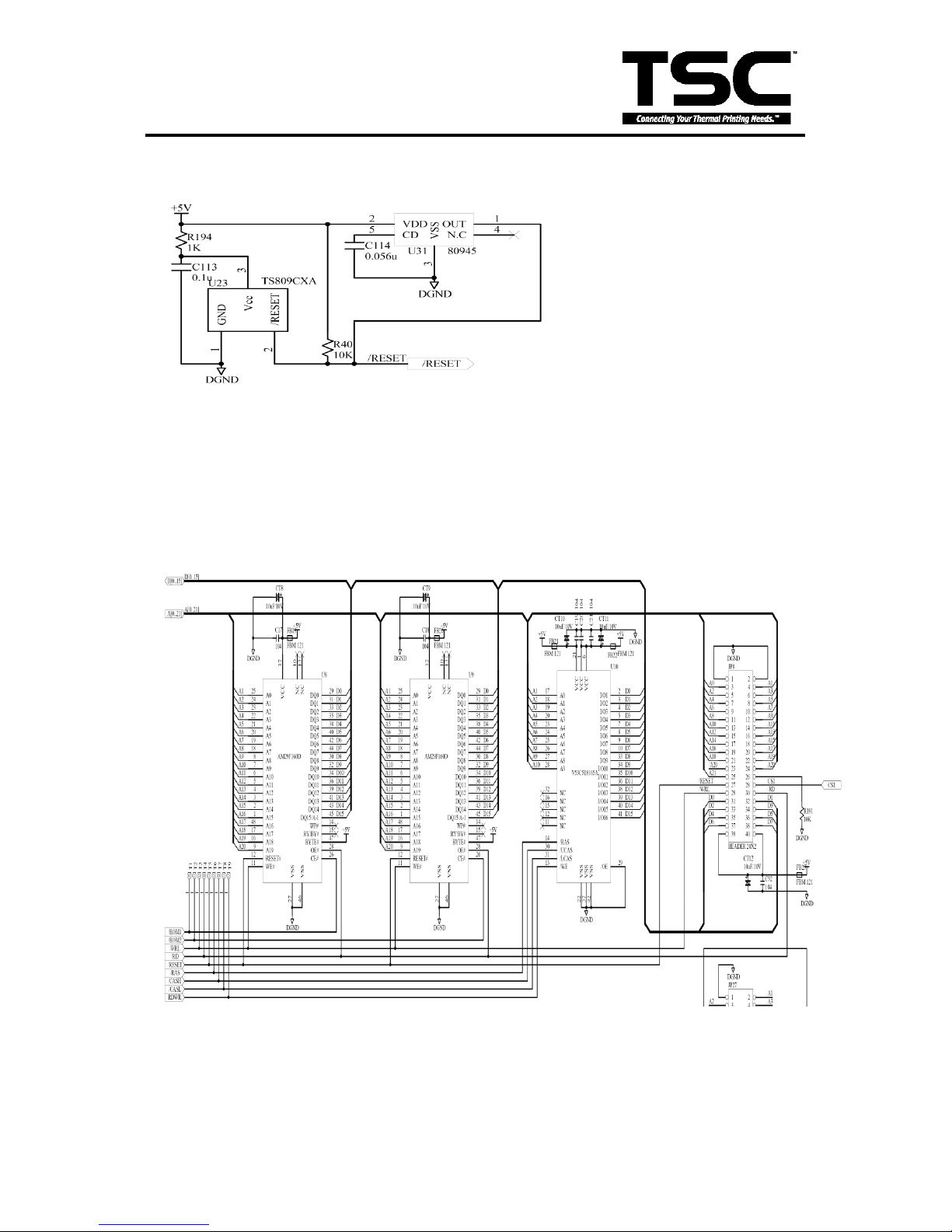
3.3 Reset Circuit
Fig. 3.3 Reset Circuit
This is the reset circuit .The TS809CXA IC outputs the system reset signal of “LOW”
when the driving voltage is lower than 4.63V (Typical),U31 NO use.
3.4 Memory System
Fig. 3.4 FLASH ROMS and DRAM Diagram
This is the memory circuit. The U8 & U9 are 2M Byte FLASH ROM and U10 is 2M Byte
DRAM .
Page 20
17
TTP-243 Plus/ 243E Plus/
342 Plus Bar Code Printer
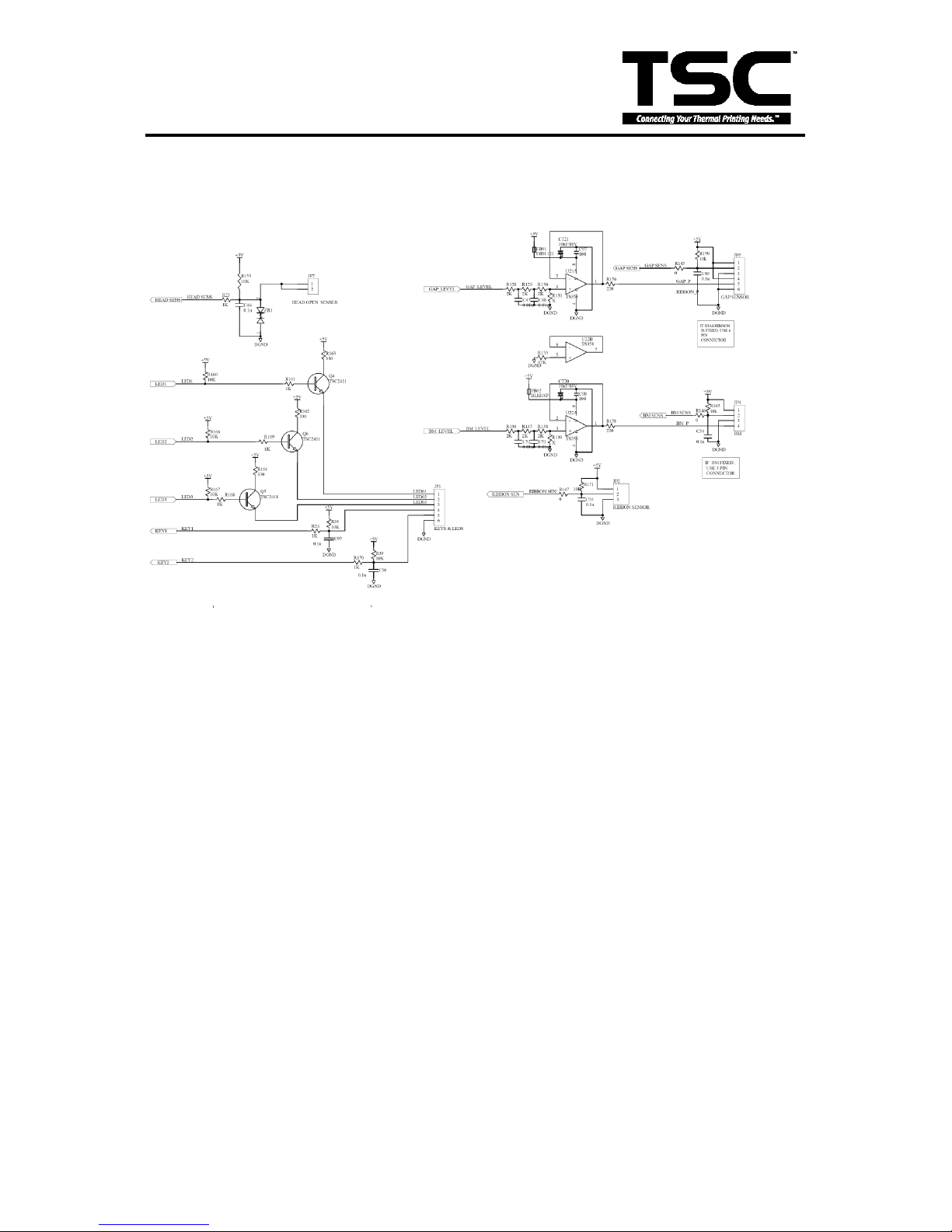
3.5 Sensor&Key
Fig. 3.5 Sensor&Key
JP1 is the connector which connects to the LEDs and Keys. The signal of LED is High when
the LED is bright; otherwise, it is low.
JP2 is the connector of the head open sensor. The Head open sensor is a micro switch. the
voltage is High when the print head open; otherwise, it is low.
The signal of the key is “LOW” when the keys is press; otherwise, t is “HIGH”.
P4 is the connector which connects to the block mark sensor.
The block mark sensor is a reflect in sensor. the block mark sensor signal voltage is “HIGH
“ when the block mark is detected; otherwise, it is “LOW”.
JP5 is the connector which connects to the gap sensor and the gap emitter level. The gap
level is a emitter source intensity control signal. signal. The gap sensor is a penetrable
sensor. the gap sensor signal voltage is low when the gap is detected; otherwise, it is high.
JP7 is the connector of the HEAD-OPEN sensor. When the printhead open,
The HEAD SENS signal is “High” ; When the printhead close, The HEAD SENS Signal
is ”LOW”.
Memory card
Memory card
Page 21
18
TTP-243 Plus/ 243E Plus/
342 Plus Bar Code Printer
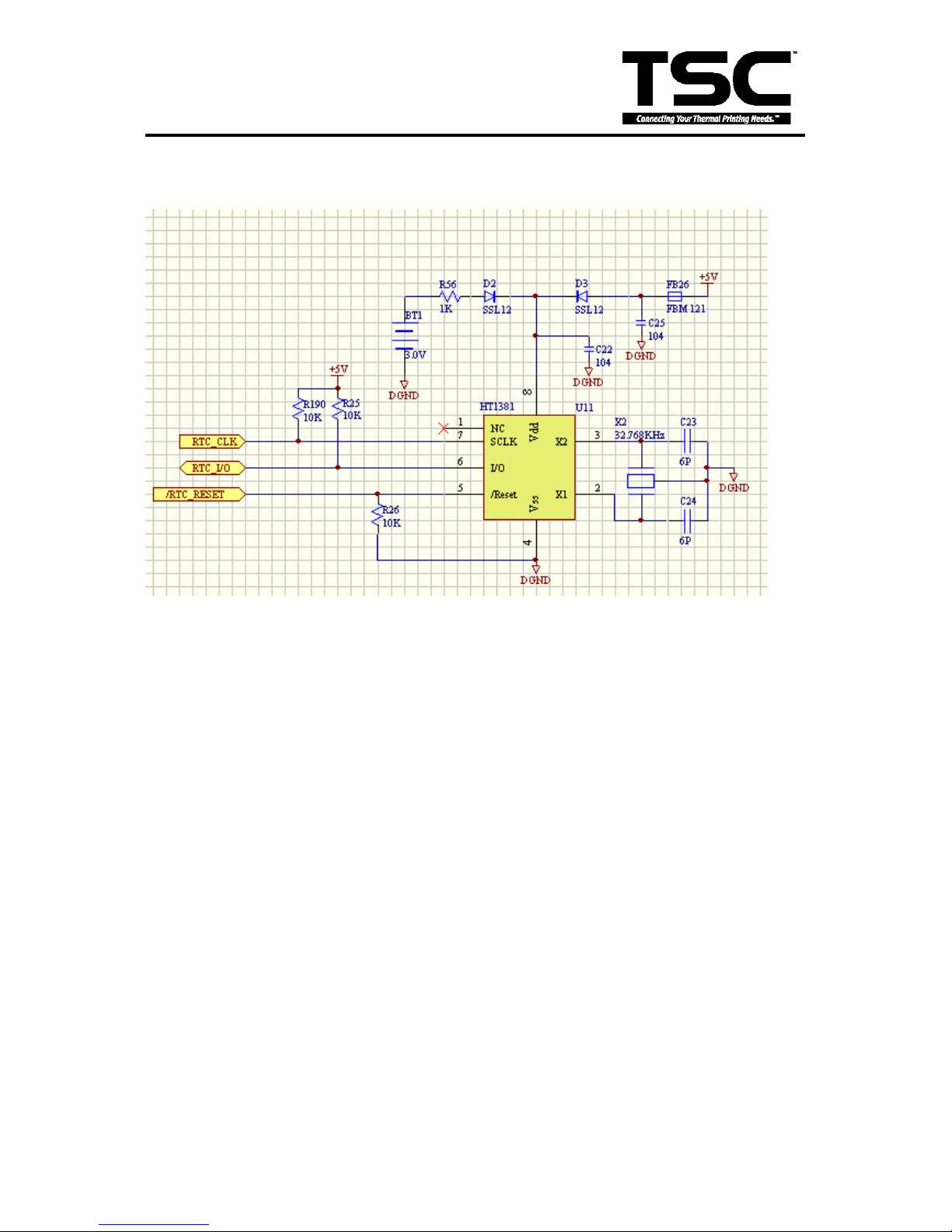
3.6 Real-Time Clock Circuit
Fig. 3.6 Real-Time Clock Circuit
HT1381 is serial time Keeper.
Page 22
19
TTP-243 Plus/ 243E Plus/
342 Plus Bar Code Printer
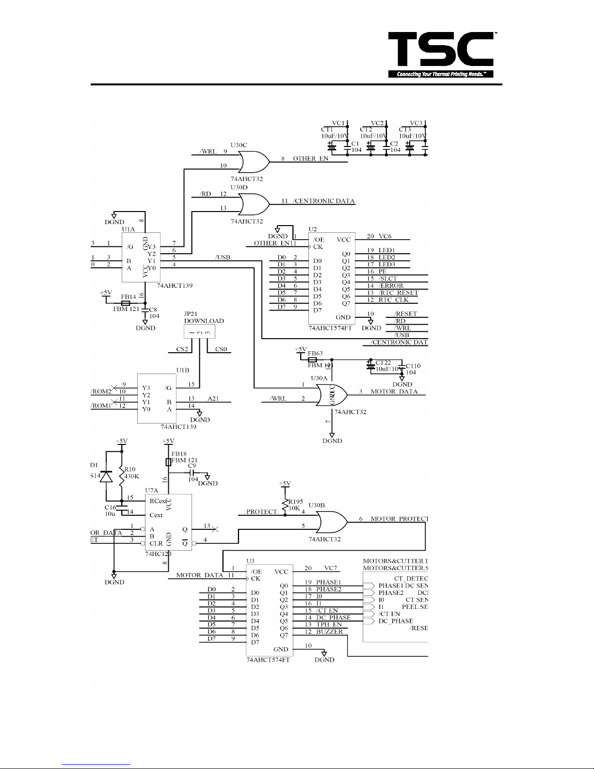
3.7 Decode Circuit
Page 23
20
TTP-243 Plus/ 243E Plus/
342 Plus Bar Code Printer
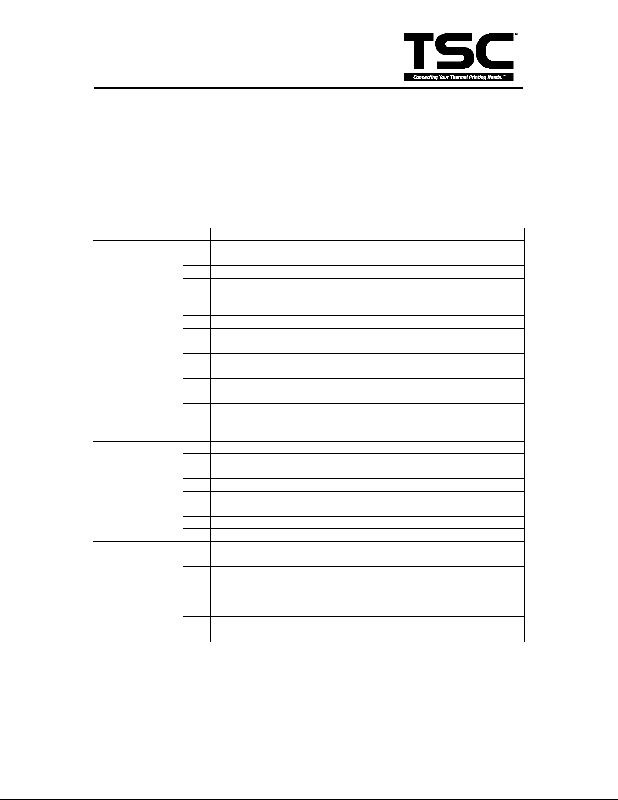
CS0: (0000 0000 ~ 003F FFFF)
CS1: (0040 0000 ~ 007F FFFF)
CS2: (0080 0000 ~ 00BF FFFF)
CS3: (00C0 0000 ~ 0FFF FFFF)
ROM1: (0000 0000 ~ 001F FFFF)
ROM2: (0020 0000 ~ 003F FFFF)
Memory card :(0040 0000~007F FFFF)
Download ROM: (0800 0000 ~ 09F FFFF)
DRAM: (0100 0000~011F~FFFF)
Other Map
Address
Bit
Function
00C0 0000
MOTOR DATA
0
PHASE1
1
PHASE2
2
I0 3 I1 4 /CT EN
5
DC PHASE
6
TPH EN
7
BUZZER
00D0 0000
/USB
0
USB_D0
1
USB_D1
2
USB_D2
3
USB_D3
4
USB_D4
5
USB_D5
6
USB_D6
7
USB_D7
00E0 0000
/CENTRONIC
DATA
0
P_D0
1
P_D1
2
P_D2
3
P_D3
4
P_D4
5
P_D5
6
P_D6
7
P_D7
00F0 0000
OTHER ENABLE
0
LED1
1
LED2
2
LED3
3
PE 4 /SLCT
5
/ERROR
6
/RTC RESET
7
RTC CLK
Page 24
21
TTP-243 Plus/ 243E Plus/
342 Plus Bar Code Printer
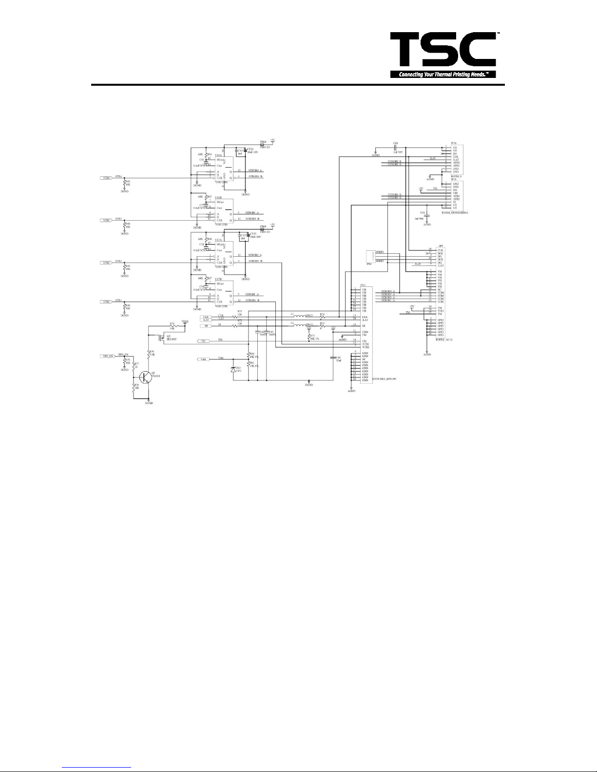
3.8 Thermal Head Drive/ Protection and History Control Circuit
Fig. 3.9 Thermal Head Drive/ Protection and History Control Circuit
This is the thermal head drive circuit. CLK and /LAT connected to thermal head control clock
and data latch respectively. TPH_EN controls the DC24V voltage of the thermal head.
When TPH_EN is “LOW”, the thermal head will be separated from 24V (VMM). STB1-STB4
determines whether to heat the thermal head or not. DI sends the printer data to the print
head. TM is the temperature for thermal head. Vdet feeds back the voltage and
compensates the heat time for voltage accuracy when printing.
Page 25
22
TTP-243 Plus/ 243E Plus/
342 Plus Bar Code Printer
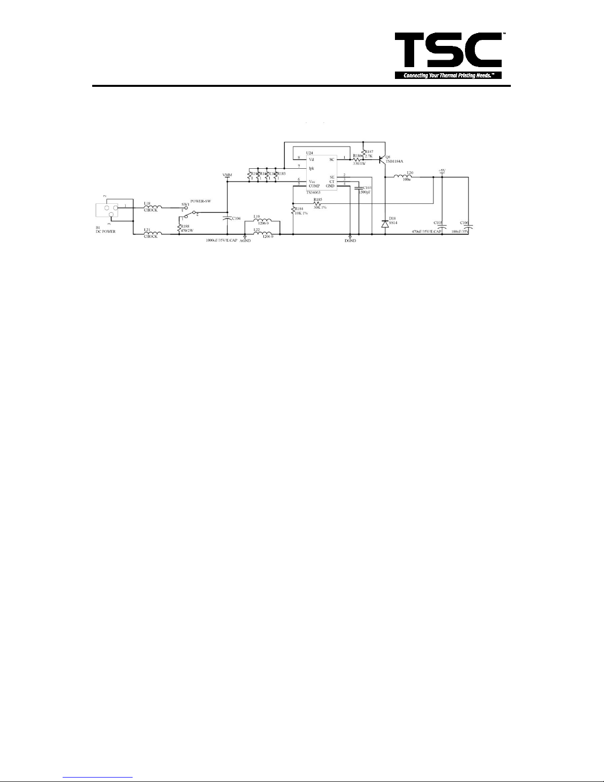
3.9 24V/5V Converter Circuit
Fig. 3.10 24V/5V Converter Circuit
Figure 3.9 is the DC-TO-DC (DC24V to DC 5V) converter circuit, which is a step-down
system circuit structure. U24 is the DC-TO-DC converter IC, which can convert voltage by
using PWM control mode. The output voltage is dependent on R3 and R4.
Page 26
23
TTP-243 Plus/ 243E Plus/
342 Plus Bar Code Printer
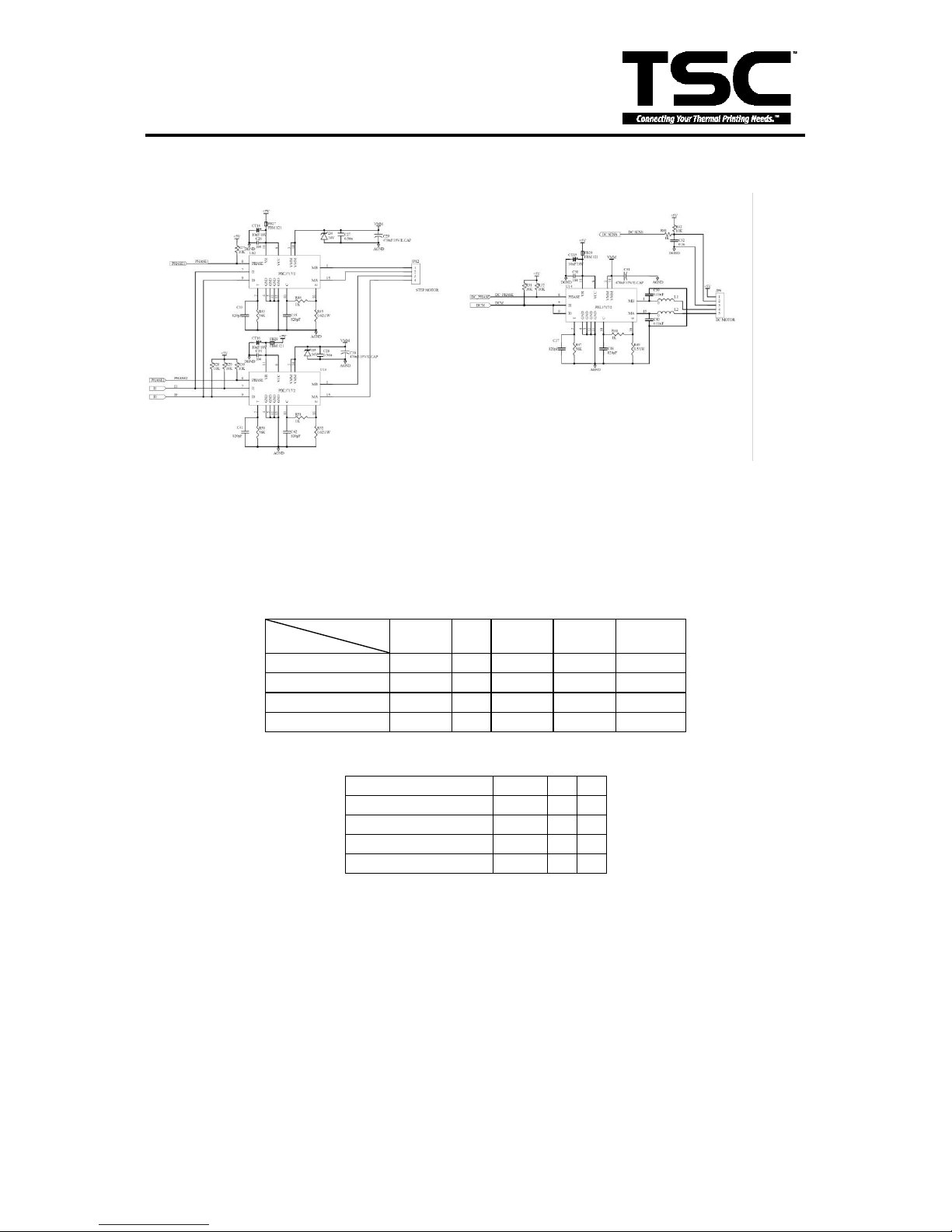
3.10 Stepping Motor And DC Motor Driver/ Protection Circuit
Fig. 3.10 Stepping Motor And DC Motor Driver/ Protection Circuit
This is the Stepping Motor Drive. Connector JP12 sends the pattern as shown in table1. The
status of I0 & I1 determines the stepping motor power level, the power level pattern is
shown in table2. PHASE1 and PHASE2 determine the pattern of stepping motor drive circuit.
For example, the sequence of PHASE1/PHASE2 in full step mode is 0/0 → 0/1 → 1/1 →
1/0.
Step
Pin on JP12
1 2 3 4 PHASE
1
ON
ON ON
A
2 ON
ON /A
3
ON ON
ON
/B 4
ON
ON B
Table1 Stepping Motor Pattern
MOTOR CURRENT
I0
I1
HIGH LEVEL
100%
L L MEDIUM LEVEL
60%
H L LOW LEVEL
20%
L H ZERO CURRENT
0% H H
Table2 Stepping motor power pattern
The power of DC motor is on when DCM pin is at ‟LOW‟ level. DC-PHASE determines the
DC motor run direction (forward or backward).
Page 27
24
TTP-243 Plus/ 243E Plus/
342 Plus Bar Code Printer
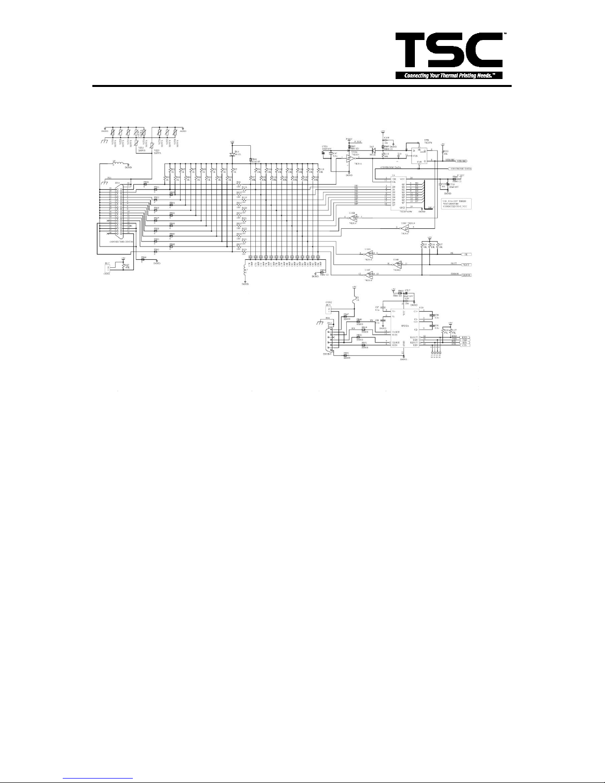
3.11 Communication (Serial & Parallel Port) Circuit
Fig. 3.11 Parallel port and RS-232 Circuit
The RS-232 Circuit is for use with the externally connected personal computer and
keyboard unit. JP13 connects to PC serial port through the RS-232 cable. RxD is the
data receive pin of MCU. CTS is the Clear To Send of MCU, which sends the signal
from the external device. TxD is the data output pin of MCU. RTS is the Request To
Send signal which MCU sends to the external device.
The parallel port circuit is for use with the externally connected personal computer
parallel port through the printer cable. When PC‟s strobe signal comes in, the printer
responds the „busy status‟ until it reads the data from parallel port. Printer will respond
the „error signal‟ to PC when it is in error status.
Page 28
25
TTP-243 Plus/ 243E Plus/
342 Plus Bar Code Printer
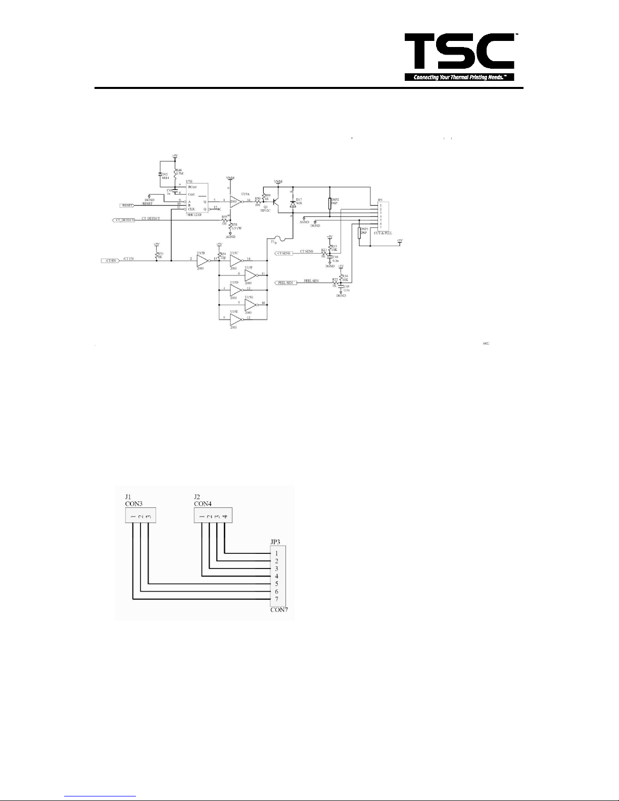
3.12 Cutter Drive Circuit
Fig. 3.12 Cutter Drive Circuit
This is the cutter drive circuit. The RESET signal is 1 when the printer is turned on.
/CT_EN controls the activation of the cutter. The cutter is activated when CUTTER
signal is “low”. The sensor of cutter sends the “Hi-Lo” signal to MCU through CT_SENS
that detects the action of cutter.
3.13 Cutter & Peel Translate Board
Cutter and peel connector circuit.
JP1 connect to peel module.
JP2 connect to cutter module.
JP3 connect to main board JP3.
Page 29
26
TTP-243 Plus/ 243E Plus/
342 Plus Bar Code Printer
3.14 Mainboard Replacement
1. Turn off the printer power.
2. Remove the power cord and RS-232 and/or parallel port cable.
3. Open the top cover of the printer.
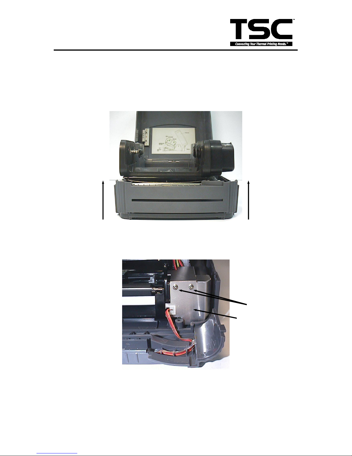
4. Remove the printer front panel.
Fig. 3.14 Remove the front cover
in the direction of the arrows
5. Remove the two screws and the metal cover.
Fig. 3.15 Remove the screws
and metal cover
Screws
Metal Cover
Page 30
27
TTP-243 Plus/ 243E Plus/
342 Plus Bar Code Printer
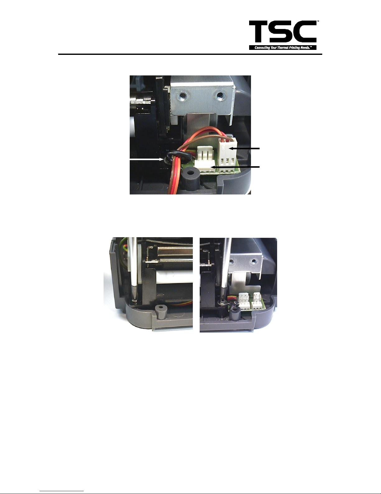
6. Release the cable tie and remove the peel-off sensor connector.
Fig. 3.16 Cable tie and peel-off sensor connector
7. Remove the screws on the lower left and lower right corners of main mechanism.
Fig. 3.17 Remove the screws in the lower left, lower
right corners of the main mechanism.
Peel-Off Sensor
Connector
Cutter Connector
Page 31
28
TTP-243 Plus/ 243E Plus/
342 Plus Bar Code Printer
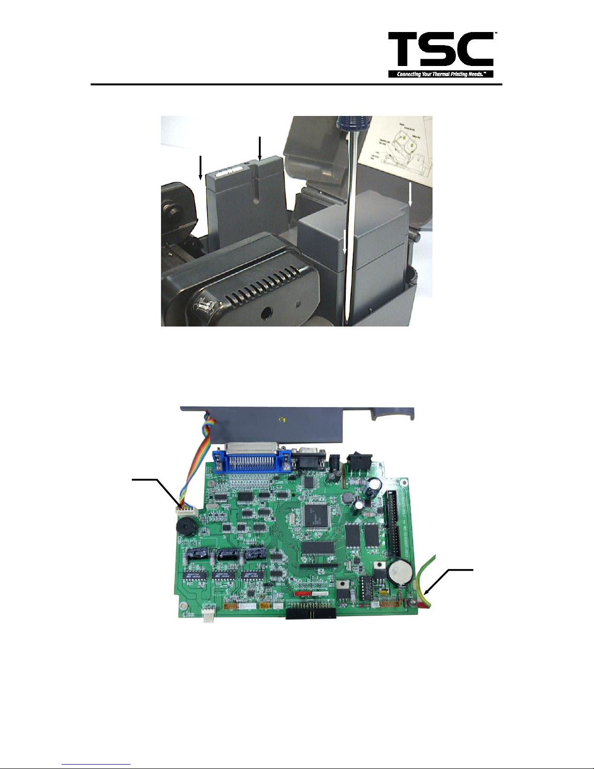
8. Remove the four screws of the internal label roll mount.
Fig. 3.18 Remove screws of the label roll mount
9. Move the mechanism about 5 mm in the label feed direction.
10. Take out the internal label roll mount and remove the connector.
Fig. 3.19 Take out the internal label roll
mount and remove the connector
Ground Wire
Push Button
Connector
Page 32
29
TTP-243 Plus/ 243E Plus/
342 Plus Bar Code Printer
11. Remove the screw of ground wire on the mainboard.
12. Remove all connectors on the mainboard. (JP1, JP2, JP3, JP4, JP5, JP6, JP7, JP11, JP7,
JP9, JP12)
Connector
Description
JP1
External button, LED connector
JP2
Ribbon sensor receiver connector
JP3
Cutter and Peel off sensor connector
JP4
Black mark sensor connector
JP5
Gap / ribbon transmit sensor
connector
JP6
DC motor and encoder connector
JP7
TPH head up switch connector
JP8
Memory cartridge connector
JP9
TPH connector
JP12
Stepping motor connector
13. Take out the mechanism.
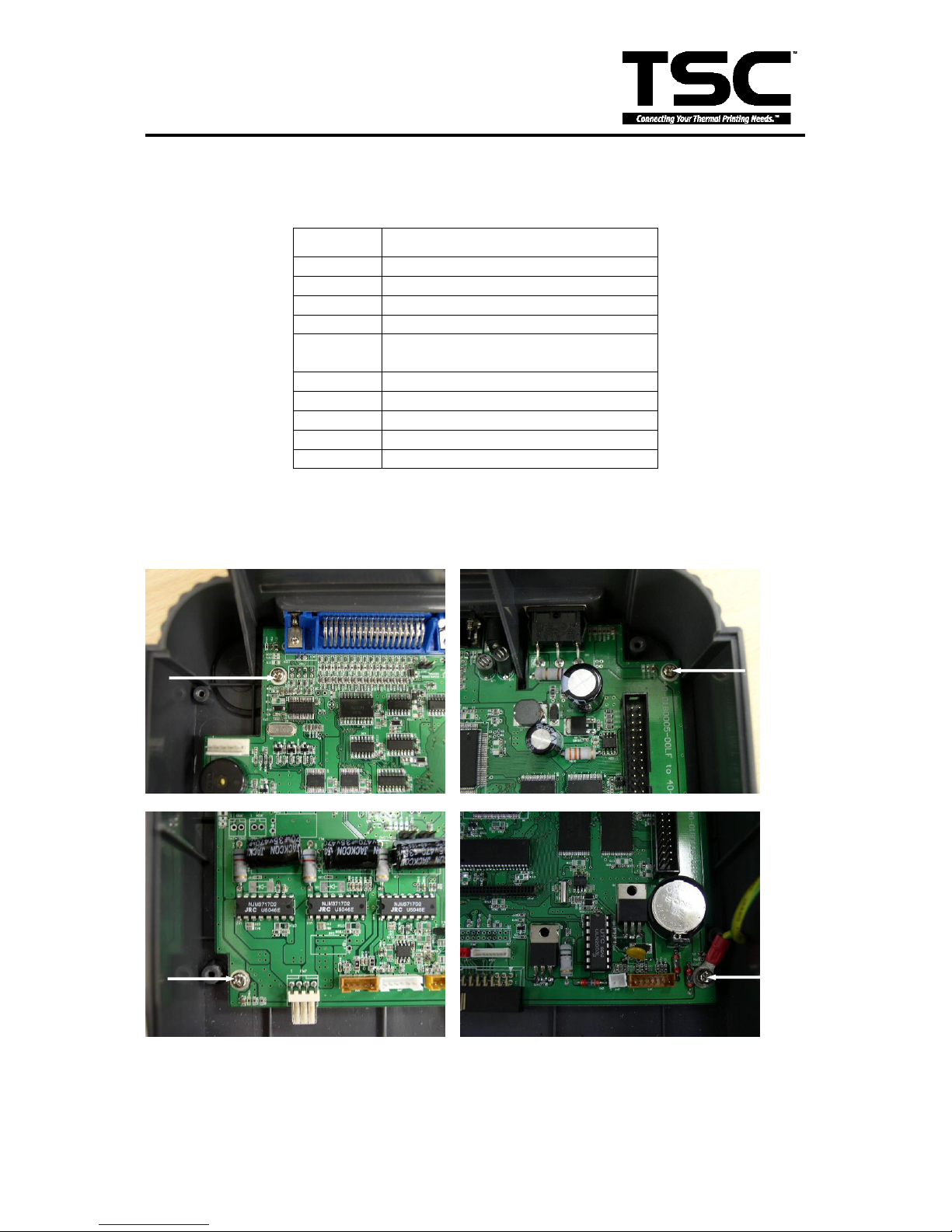
14. Remove the rest three screws on the mainboard.
Fig. 3.20 Upper-Left, Upper-Right, Lower-Right Corner Screw
15. Replace the mainboard.
16. Reassemble the mechanism and internal label roll mount in the reverse procedures of the removal.
Page 33
30
TTP-243 Plus/ 243E Plus/
342 Plus Bar Code Printer
3.15 Cutter, DC Motor, Stepping Motor Driver IC Replacement
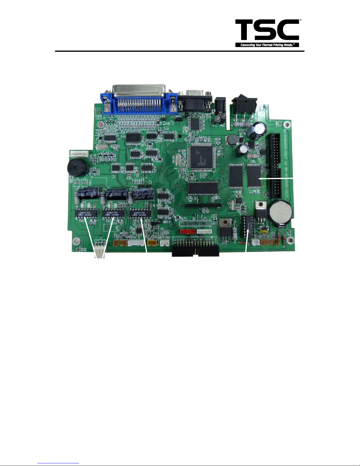
Fig. 3.22 Driver IC Locations
If the DC motor (ribbon rewind spindle) rotates back and forth, please check the DC
motor driver IC, make sure it is firmly inserted in the IC socket and is not burned.
If the cutter does not work, please check that the software or program has been
switched to the cutter mode. If the cutter still does not function, please check the cutter
driver IC, make sure it is firmly inserted in the IC socket and is not burned.
The stepping motor driver IC is burned if the stepping motor makes noises but does not
feed labels when the FEED key is pressed. In this case, please replace with a new
driver IC.
Use an IC clamp to remove the damaged IC.
Stepping
Motor Driver IC
DC Motor
Driver IC
FLASH
Memory
Cutter Driver IC
Page 34
31
TTP-243 Plus/ 243E Plus/
342 Plus Bar Code Printer
4. MECHANISM
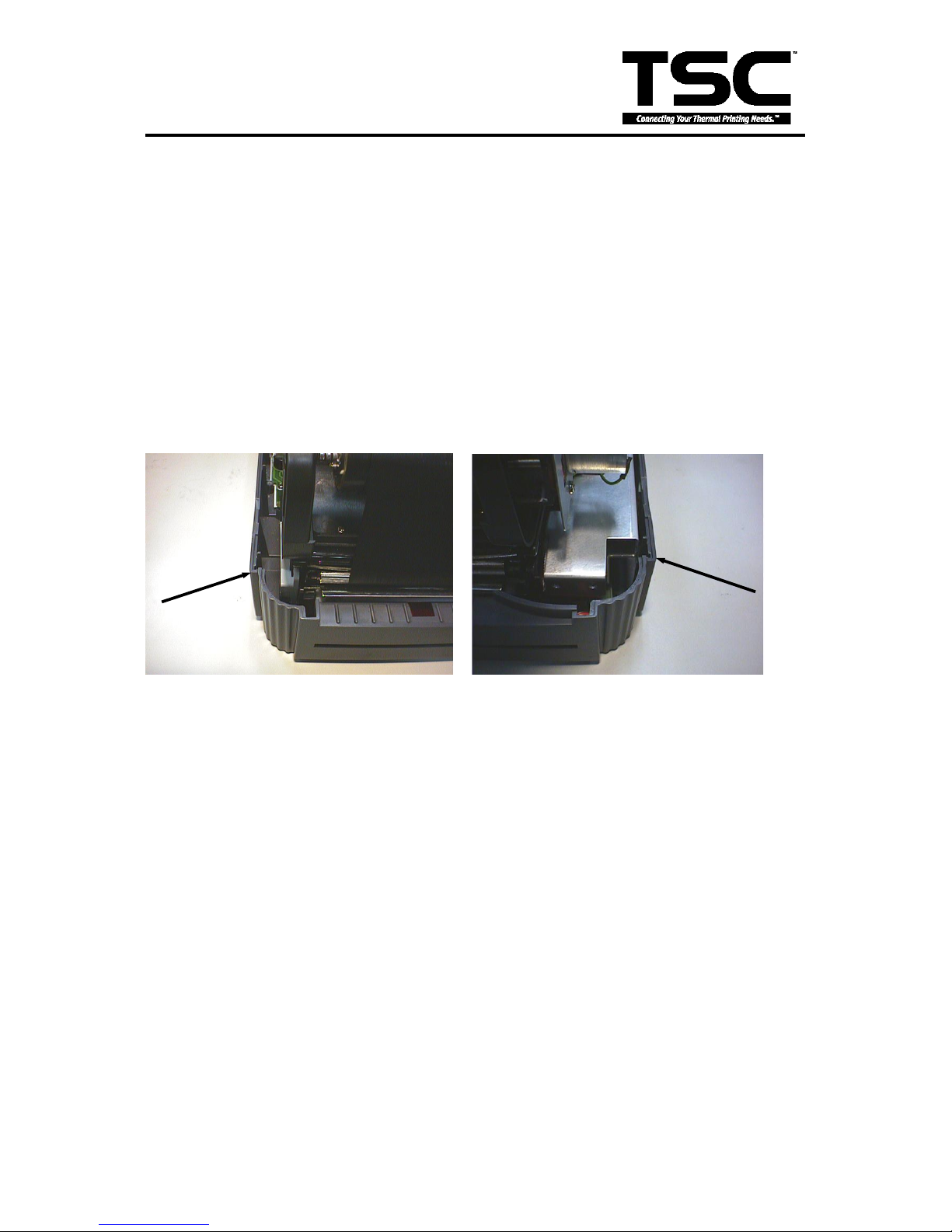
4.1 Cutter Installation
1. Turn off the printer power.
2. Open the top cover of the printer.
3. Remove the printer front panel slowly and carefully. (Cf. Fig. 3.14)
4. Remove the two screws and the metal cover. (Cf. Fig. 3.15)
5. Release the cable tie and remove the peel-off sensor connector. (Cf. Fig. 3.16)
6. Remove the peel-off sensor connector.
7. Plug in the cutter connector.
8. Insert the right and left side flange of cutter into the slot.
Fig. 4.1 Cutter Installation
9. Fasten the cutter from the bottom of the printer with the provided screw.
10. Make sure no screws or other parts are left in the printer.
11. Reassemble the mechanism and internal label roll mount in the reverse procedures of the
removal.
Right Flange
Left Flange
Page 35
32
TTP-243 Plus/ 243E Plus/
342 Plus Bar Code Printer
4.2 Print Head Replacement
1. Turn off the printer power.
2. Remove the RS-232 cable and power cord.
3. Open the top cover.
4. Remove the ribbon and label roll.
5. Open the print carriage.
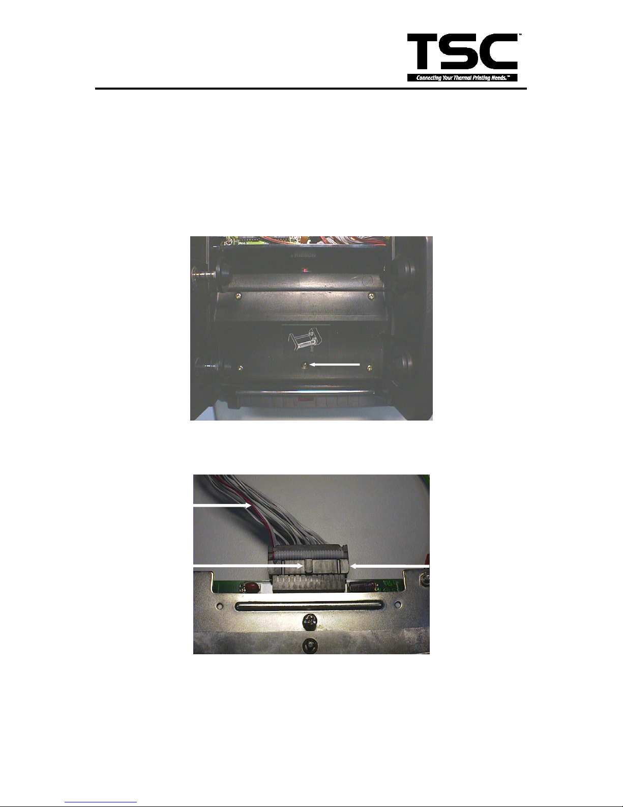
6. Remove the screw at the top front center of the mechanism, as shown.
Fig. 4.2 The Print Head Screw
7. Disconnect the print head cable.
Fig. 4.3 Printhead and the Cable
Print Head
Connector
Key of the
Connector
Print Head
Cable
Page 36

33
TTP-243 Plus/ 243E Plus/
342 Plus Bar Code Printer
Note: The key of connector must be positioned upward.
Do not touch the elements of the print head.
Do not disassemble the print head.
8. Tidy up the cable so that it does not protrude or interfere with the ribbon.
9. Reassemble the removed parts in the reverse order of removal.
Page 37
34
TTP-243 Plus/ 243E Plus/
342 Plus Bar Code Printer
4.3 DC Motor Replacement
1. Turn off the printer power.
2. Remove the power cord and RS-232 and/or parallel port cable.
3. Open the top cover of the printer.
4. Remove the printer front panel. (Cf. Fig. 3.14)
5. Remove the two screws and the metal cover. (Cf. Fig. 3.15)
6. Release the cable tie and remove the peel-off sensor connector. (Cf. Fig. 3.16)
7. Remove the screw on the PCB of peel-off and cutter connector.
8. Remove the screws in the lower left, lower right corners of the main mechanism. (Cf. Fig. 3.17)
9. Remove all four screws of the internal label roll mount. (Cf. Fig. 3.18)
10. Move the mechanism in the label feed direction about 5 mm.
11. Take out the internal label roll mount and remove connector JP1. (Cf. Fig. 3.19)
12. Remove the screw of ground wire on the mainboard.
13. Remove all connectors on the mainboard.
14. Take out the mechanism.
15. Remove the cable tie.
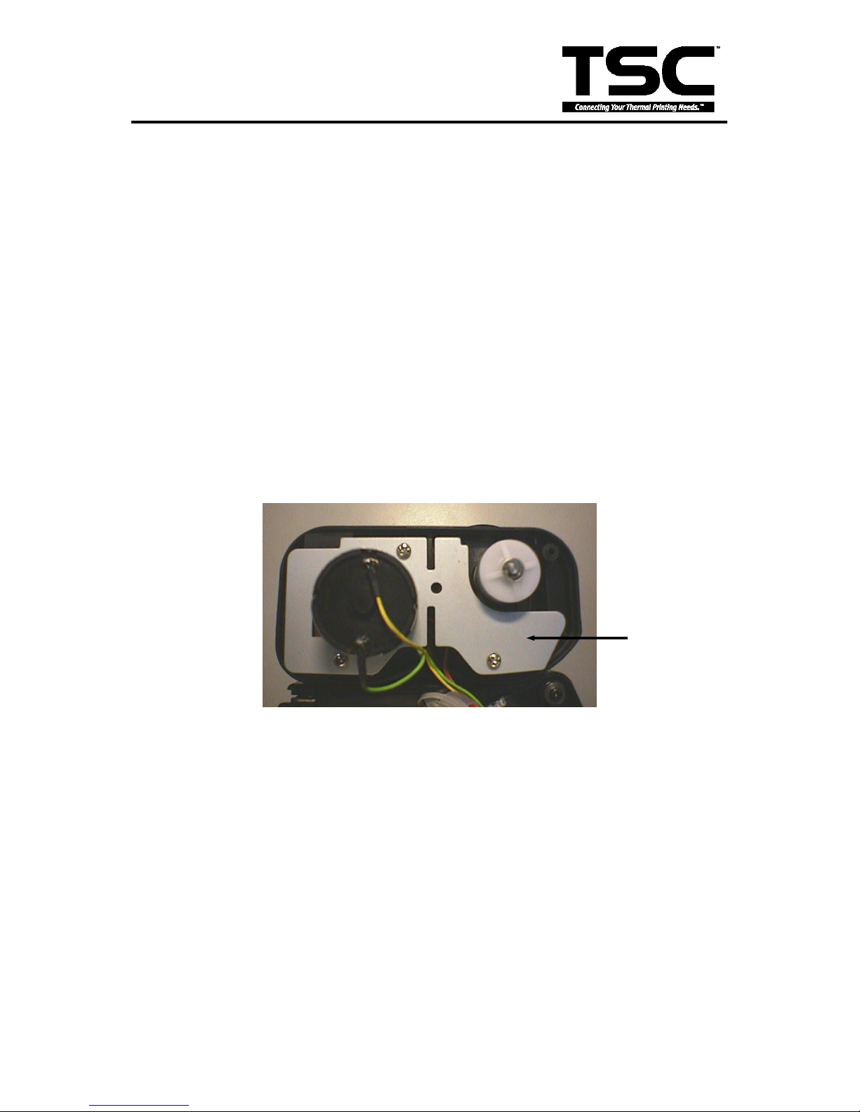
16. Remove the three screws on DC motor fixture.
Fig. 4.4 DC Motor Fixture
17. Remove the two screws used to fix DC motor on the fixture.
18. Replace the DC motor and pull out the cables in connector No. 6.
Note: The colors of DC motor wires in connector No. 6 are yellow (outside) and green
(inside).
19. Reassemble the removed parts in the reverse order of the removal.
4.4 Ribbon Rewind Spindle Encoder Replacement
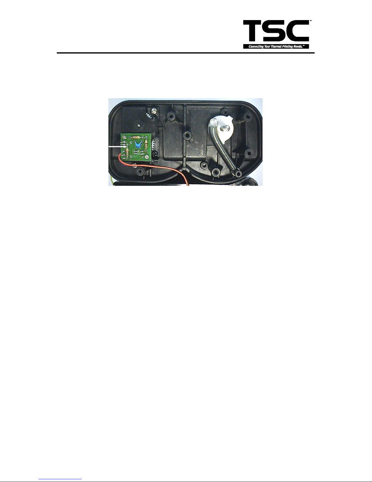
The encoder is installed on the gear box of DC motor, and is used to detect if the ribbon
is unerringly rewound by the spindle. The encoder is connected to JP6 on the
mainboard. Please switch the printer to thermal transfer mode. The multi-meter is used
DC Motor
Fixture
Page 38
35
TTP-243 Plus/ 243E Plus/
342 Plus Bar Code Printer
to measure the voltage of Pin2 (+5V). If the voltage changes continuously from 0 to 5
volts DC, the encoder is in condition. Otherwise, please follow the steps below to
replace the encoder PCB
1. Follow directions in Section 4.3 to remove DC motor and DC motor fixture.
Fig. 4.5 DC Motor Encoder
2. Remove the two flat tap screws and cable tie.
3. Replace the Encoder PCB.
4. Reassemble the removed parts in the reverse order of removal.
DC Motor
Encoder
Page 39
36
TTP-243 Plus/ 243E Plus/
342 Plus Bar Code Printer
4.5 Felt Fabric Replacement
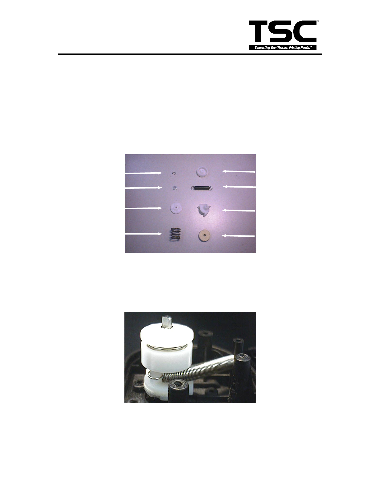
Felt Fabric is located in the ribbon supply spindle. It is used to tighten the ribbon to
prevent it from getting wrinkled during printing. If the ribbon can not be tightened when
label back feeds during printing, please replace with a new felt to secure the best
printing quality. Follow the steps below to replace the felt fabric.
1. Follow the instructions in Section 4.3 to remove DC motor and DC motor fixture.
2. Remove the E-ring and washer on ribbon supply spindle.
Fig. 4.6 Components of the
Ribbon Supply Spindle
3. Remove the spring cover, compression spring and spring holder.
4. Remove the spring, felt clutch and felt fabric.
5. Replace with a new felt.
Fig. 4.7 Side View of the
Ribbon Supply Spindle Assembly
E Ring
Washer
Spring Cover
Compression
Spring
Spring Holder
Spring
Felt Clutch
Felt Fabric
Page 40
37
TTP-243 Plus/ 243E Plus/
342 Plus Bar Code Printer
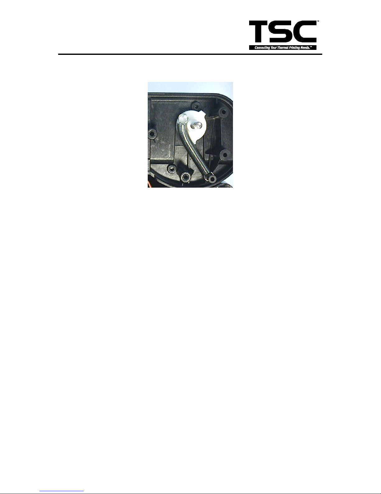
6. Reassemble the removed parts in the reverse order of removal.
Fig. 4.8 Front View of the
Ribbon Supply Spindle
Page 41
38
TTP-243 Plus/ 243E Plus/
342 Plus Bar Code Printer
4.6 Stepping Motor Replacement
1. Turn off the printer power.
2. Remove the power cord and RS-232 and/or Parallel port cable.
3. Open the top cover of the printer.
4. Remove the printer front panel. (Cf. Fig. 3.14)
5. Remove the two screws and the metal cover. (Cf. Fig. 3.15)
6. Release the cable tie and remove the peel-off sensor connector. (Cf. Fig. 3.16)
7. Remove the screw on the PCB of peel-off and cutter connector.
8. Remove the screws in the lower left, lower right corners of the main mechanism. (Cf. Fig.
3.17)
9. Remove all four screws of the internal label roll mount. (Cf. Fig. 3.18)
10. Move the mechanism in the label feed direction about 5 mm.
11. Take out the internal label roll mount and remove the connector. (Cf. Fig. 3.19)
12. Remove the screw of ground wire on the mainboard.
13. Remove all the connectors on mainboard. (JP1, JP2, JP3, JP4, JP5, JP6, JP7, JP11, JP7,
JP9, JP12)
14. Take out the mechanism.
15. Remove the rest three screws on the mainboard.
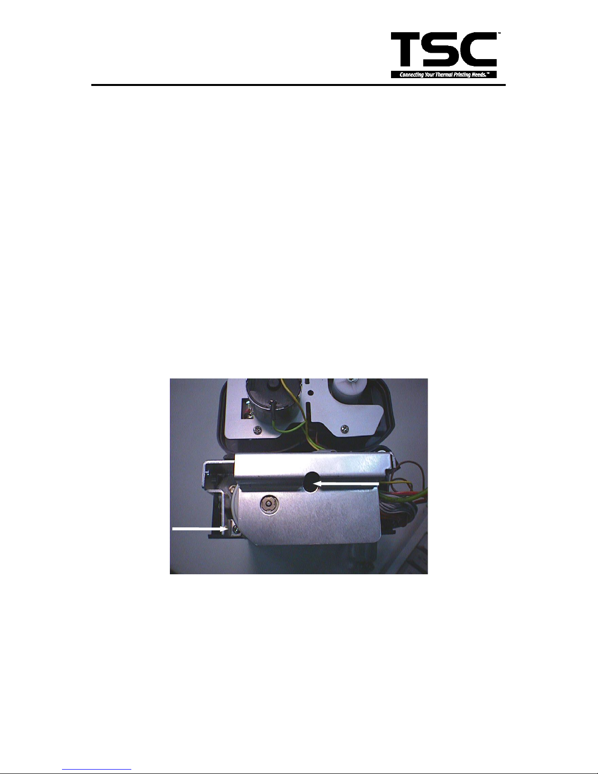
16. Remove the two screws of the stepping motor.
Fig. 4.9 Stepping Motor
17. Replace the stepping motor and reassemble the removed parts in the reverse order of
removal.
Page 42
39
TTP-243 Plus/ 243E Plus/
342 Plus Bar Code Printer
4.7 Black Mark Sensor / Gap Sensor (Receiver) Replacement
Black mark sensor is reflection type sensor. It is connected to JP4 (3 pin connector). A
multi-meter is used to measure the signal of Pin2 to see if there is voltage variation
when black mark is detected. Before conducting the test, please issue the BLINE
command first. The printer will switch from gap sensor to black mark sensor. If there is
no voltage variation, please follow steps below to replace the black mark sensor / gap
sensor (receiver) PCB.
1. Turn off the printer power.
2. Remove the power cord and RS-232 and/or parallel port cable.
3. Open the top cover of the printer.
4. Remove the printer front panel. (Cf. Fig. 3.14)
5. Remove the two screws and the metal cover. (Cf. Fig. 3.15)
6. Release the cable tie and remove the peel-off sensor connector. (Cf. Fig. 3.16)
7. Remove the screw on the PCB of peel-off and cutter connector.
8. Remove the screws in the lower left, lower right corners of the main mechanism. (Cf. Fig.
3.17)
9. Remove all four screws of the internal label roll mount. (Cf. Fig. 3.18)
10. Move the mechanism in the label feed direction about 5 mm.
11. Take out the internal label roll mount and remove the connector. (Cf. Fig. 3.19)
12. Remove the screw of ground wire on the mainboard.
13. Remove all the connectors on mainboard. (JP1, JP2, JP3, JP4, JP5, JP6, JP7, JP11, JP7,
JP9, JP12)
14. Take out the mechanism.
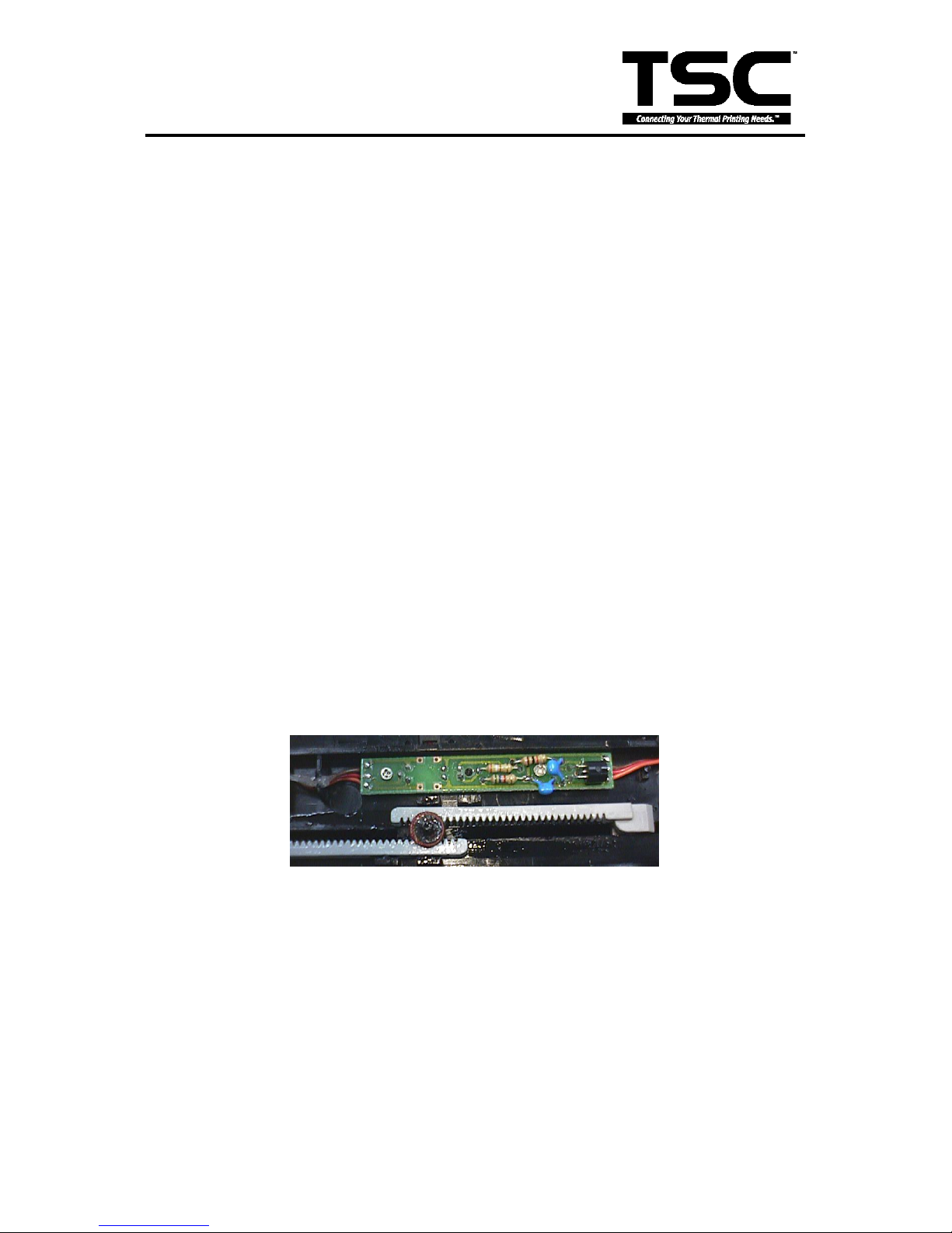
15. Remove one flat tap screws and black mark sensor PCB.
Fig. 4.10 Black Mark Sensor and Gap Receiver Sensor
16. Reassemble the removed parts in the reverse order of removal.
4.8 Ribbon Sensor (Receiver) Replacement
1. Turn off the printer power.
2. Remove the power cord and RS-232 and/or parallel port cable.
3. Open the top cover of the printer.
4. Remove the printer front panel. (Cf. Fig. 3.14)
Page 43
40
TTP-243 Plus/ 243E Plus/
342 Plus Bar Code Printer
5. Remove the two screws and the metal cover. (Cf. Fig. 3.15)
6. Release the cable tie and remove the peel-off sensor connector. (Cf. Fig. 3.16)
7. Remove the screw on the PCB of peel-off and cutter connector.
8. Remove the screws in the lower left, lower right corners of the main mechanism. (Cf. Fig. 3.17)
9. Remove all four screws of the internal label roll mount. (Cf. Fig. 3.18)
10. Move the mechanism in the label feed direction about 5 mm.
11. Take out the internal label roll mount and remove the connector. (Cf. Fig. 3.19)
12. Remove the screw of ground wire on the mainboard.
13. Remove all the connectors on mainboard. (JP1, JP2, JP3, JP4, JP5, JP6, JP7, JP11, JP7,
JP9, JP12)
14. Take out the mechanism.
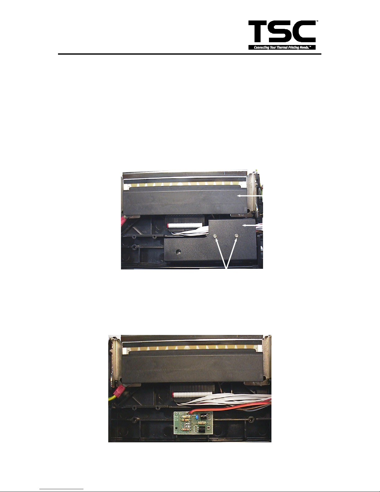
15. Remove the screws, springs and spring bushing on both sides of the mechanism.
Fig. 4.11 Ribbon Sensor Cover
Flat Tap Screw
Sensor Cover
Print Head
Page 44
41
TTP-243 Plus/ 243E Plus/
342 Plus Bar Code Printer
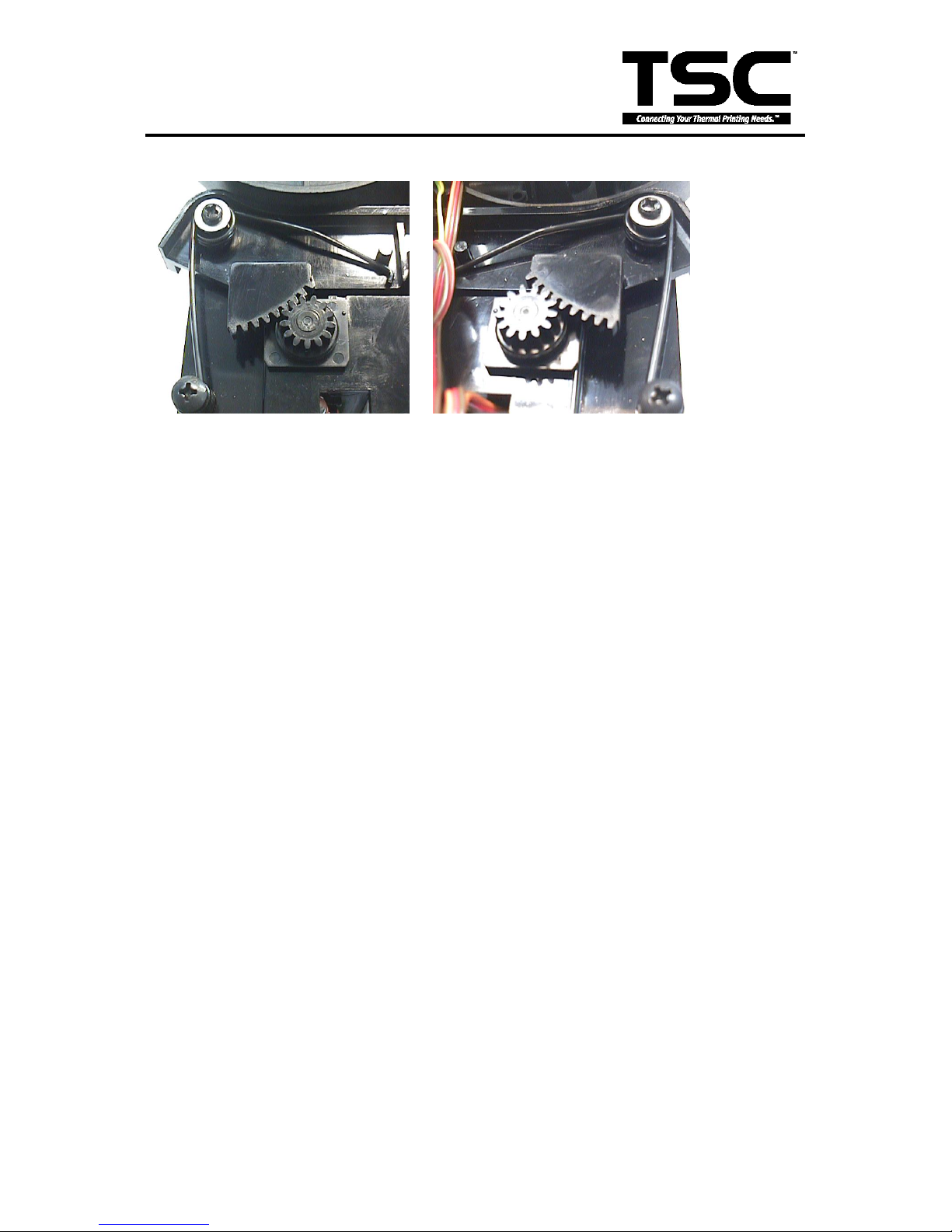
Fig. 4.12 Ribbon Sensor
Fig. 4.13 Spring Installation on Left Side and Right Side
Note: The left side spring and the right side spring are different in shape. The right
side spring has a straight end, when the left side spring has an end that is
curved 90 degrees.
16. The main mechanism is divided into upper mechanism and lower mechanism.
17. The ribbon sensor (receiver) is located in the upper mechanism.
18. Remove the screws on the ribbon sensor cover.
19. Replace with a new ribbon sensor PCB.
20. Reassemble the removed parts in the reverse order of removal.
Page 45
42
TTP-243 Plus/ 243E Plus/
342 Plus Bar Code Printer
4.9 Ribbon Sensor (Transmitter) / Gap Sensor (Transmitter) Replacement
1. Please follow the steps in Section 4.6 to separate the upper mechanism from the lower
mechanism.
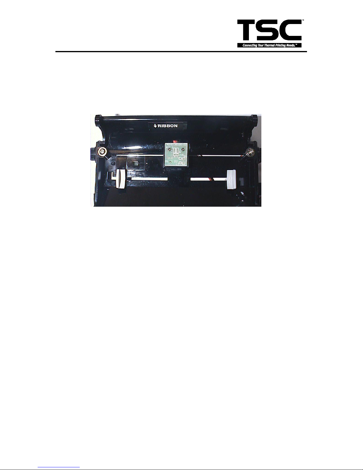
2. The ribbon sensor (transmitter) is located in the center of the lower mechanism.
Fig. 4.14 Ribbon Sensor (Transmitter)
3. Remove the two flat tap screws
4. Remove the cable tie and sensor PCB.
5. Replace with a new PCB. Reassemble the removed parts in the reverse order of removal.
Page 46
43
TTP-243 Plus/ 243E Plus/
342 Plus Bar Code Printer
4.10 Platen Replacement
1. Turn off the printer power.
2. Remove the power cord and RS-232 and/or parallel port cable.
3. Open the top cover of the printer.
4. Remove the printer front panel. (Cf. Fig. 3.4)
5. Remove the two screws and the metal cover. (Cf. Fig. 3.15)
6. Release the cable tie and remove the peel-off sensor connector. (Cf. Fig. 3.16)
7. Remove the screw on the PCB of peel-off and cutter connector.
8. Remove the screws in the lower left, lower right corners of the main mechanism. (Cf. Fig. 3.17)
9. Remove all four screws of the internal label roll mount. (Cf. Fig. 3.18)
10. Move the mechanism in the label feed direction about 5 mm.
11. Take out the internal label roll mount and remove the connector. (Cf. Fig. 3.19)
12. Remove the screw of ground wire on the mainboard.
13. Remove all the connectors on the mainboard. (JP1, JP2, JP3, JP4, JP5, JP6, JP7, JP11, JP7,
JP9, JP12)
14. Take out the mechanism.
15. Remove the two screws, stepping motor and stepping motor cover. (Cf. Fig. 4.9)
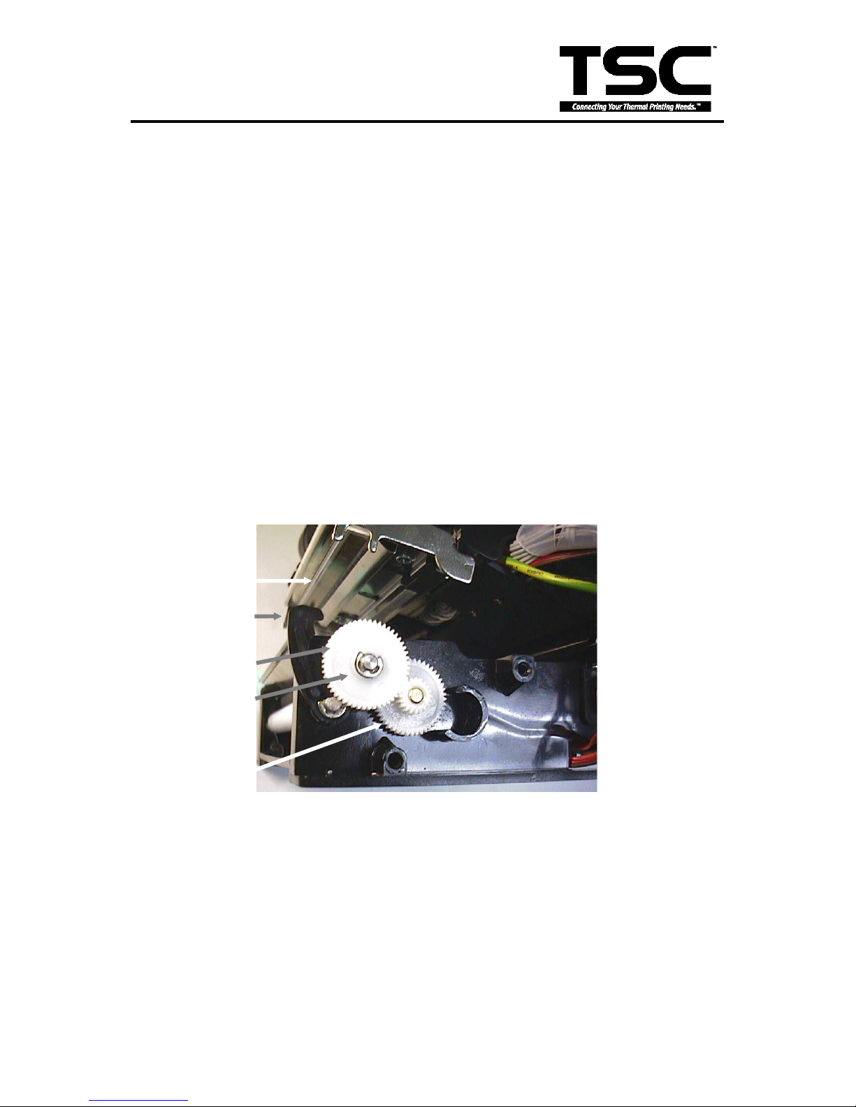
16. Remove the E ring and two gears.
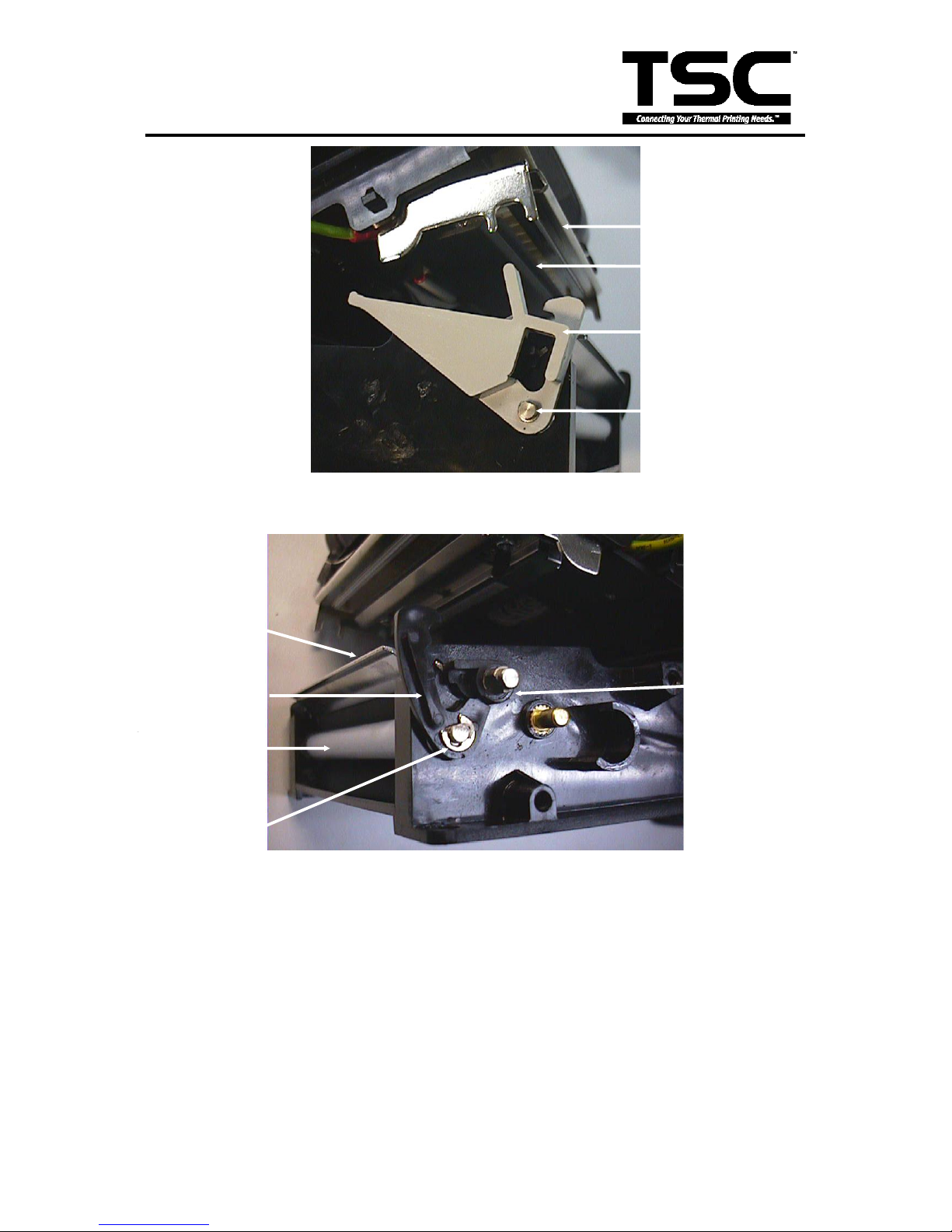
Fig. 4.15 Location of E ring and Gears
17. Remove the E ring and the printer carriage release lever on the left side of the mechanism.
18. Remove the E ring and the printer carriage release lever arm. (Fig. 4.15)
Thermal Head
Gear #1
E Ring
Gear #2
Printer Carriage
Release lever arm
Page 47
44
TTP-243 Plus/ 243E Plus/
342 Plus Bar Code Printer
Fig. 4.16 Printer carriage release lever and E ring
Fig. 4.17 Printer carriage release lever arm and E ring
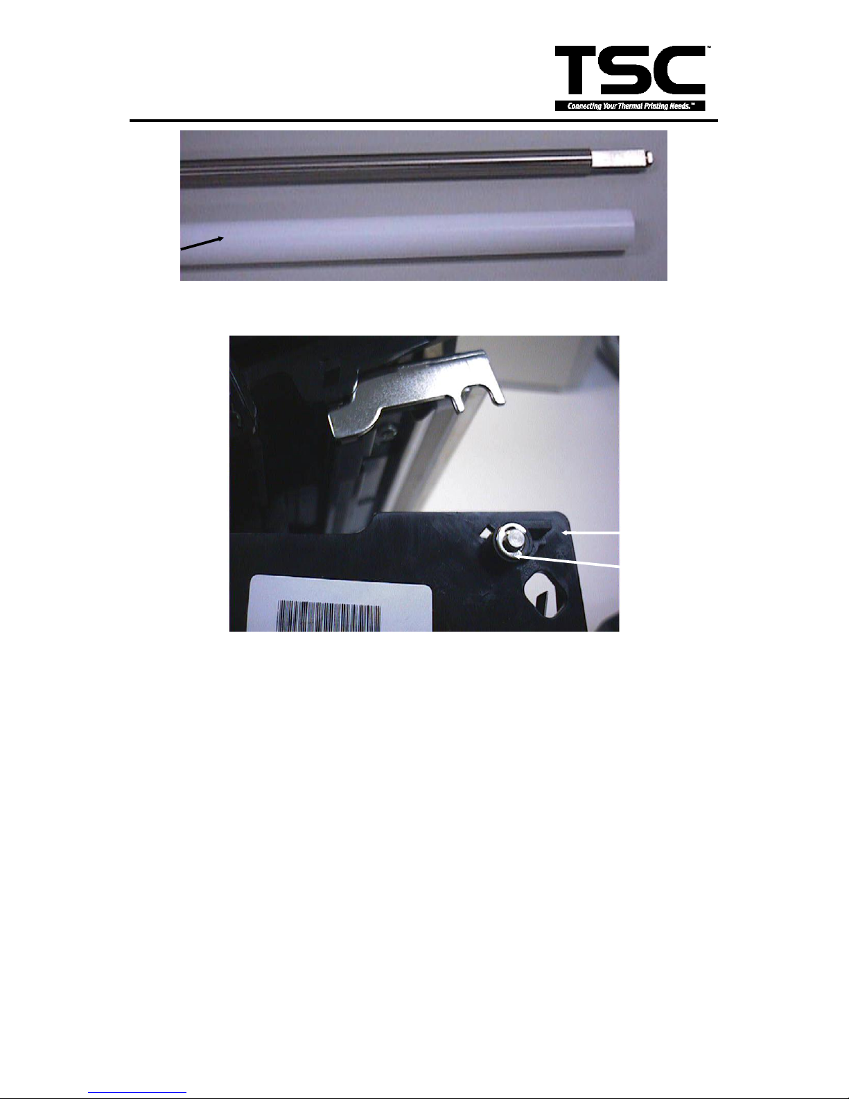
19. Remove the teflon tube and stripper rod. (Fig. 4.18)
20. Remove the E ring, the right side and left side platen bushes. (Fig. 4.19)
21. Remove the stripper bar. (Fig. 4.17)
Printer
Carriage
E Ring
Thermal Head
Bracket
E Ring
Teflon Tube
Printer
Carriage
Release Lever
Stripper
Platen Bush
(Right Side)
Page 48
45
TTP-243 Plus/ 243E Plus/
342 Plus Bar Code Printer
Fig. 4.18 Teflon tube and stripper rod
Fig. 4.19 Remove E ring and platen bush
22. Move the platen to the right of the mechanism.
23. Replace the platen and reassemble the removed parts in the reverse order of removal.
Teflon Tube
E Ring
Platen Bush
(Left Side)
Page 49

46
TTP-243 Plus/ 243E Plus/
342 Plus Bar Code Printer
5. TROUBLE SHOOTING
5.1 Error Messages
Syntax Error:
The command format is incorrect. Check user‟s manual to be sure.
The serial port setting is incorrect. Check DIP switch and reset the printer.
Out of Range:
Numeric input is too large to be processed.
The input string is too long to be stored.
The size of the text of bar code exceeds that of the label.
Download Error:
The format of the downloaded file is incorrect.
There is not enough memory to store the file.
Stack Overflow:
Program contains too complex mathematical expressions. Divide into several expressions.
There is too much nested routine.
Memory Error:
Too many variables defined.
RS-232 Error:
The serial port setting is incorrect.
File Not Found:
Cannot open the file specified. Download the file again.
Type Mismatch:
Variable type mismatch.
Gap Not Found:
Cannot detect label edge. Calibrate the backing paper again.
Clock Access Error:
Can not read from/write to the clock.
Page 50
47
TTP-243 Plus/ 243E Plus/
342 Plus Bar Code Printer
5.2 Trouble Shooting
Problems
Solutions
1. Ribbon does not advance.
Check the printing mode setting and reset the
printer.
2. Poor print quality.
Clean the print head.
Adjust the print density setting.
3. Only prints diagonal pattern in the self-test.
Ribbon and paper are incompatible. Use a
different type of ribbon.
4. Power indicator light does not illuminate.
Check the connection of serial port cable.
5. On-line indicator light does not to illuminate.
Check the DIP switch setting and reset the
printer.
Check that power cord is properly connected.
6. Error indicator remains illuminated.
Out of paper or out of ribbon.
Check the DIP switch setting
Check the paper core, make sure it is installed
on the ribbon rewind spindle.
Press the FEED key. The error message will
be printed out on the print media or sent out
through RS-232 port.
If there is no problem with direct thermal
printing, but error occurs in thermal transfer
printing. Please check the encoder of the DC
motor.
Page 51

48
TTP-243 Plus/ 243E Plus/
342 Plus Bar Code Printer
5.3 Calibrate the Gap Register
Install the label.
Turn on the printer power while pressing the PAUSE button. The printer will calibrate the
transparency of the backing paper and adjust the gap register.
5.4 Self-test
Install the label.
Turn on the printer power while pressing the FEED button, the printer will:
Print head checking pattern.
Calibrate the label length.
Print internal settings.
Initiate self-test.
Enter dump mode.
5.5 Ram Clear
Press the PAUSE and FEED button simultaneously for more than 3 seconds. The printer will
clear the memory and reset the printer.
Be sure to calibrate the gap register with blank label before printing.
5.6 Diagnosis Operation Procedure
When the power is turned on without any button pressed, self diagnosis is performed
automatically to test the available memory. If any error occurs during this period, the ERR
light will flash.
Do the self test and inspect the test pattern to check if the thermal head is available.
Page 52

49
TTP-243 Plus/ 243E Plus/
342 Plus Bar Code Printer
5.7 Testing Sensors
A. Checking Ribbon Sensor
Switch the multimeter to the DC gear. Connect the black wire to DC GND, and the red
wire to PIN2 of JP2.
1. When ribbon is detected between TX and RX of the ribbon sensor, the measured
voltage should be 5 Vdc.
2. When ribbon is not detected between TX and RX of the ribbon sensor, the measured
voltage should be 0 Vdc.
The ribbon sensor is normal if the checking complies with the two cases above. Or else,
the ribbon sensor is out of order.
B. Checking DC Motor Encoder Sensor
Switch the multimeter to the DC gear. Connect the black wire to DC GND, and the red
wire to PIN2 of JP6.
1. When gap of the gear box is detected by the DC motor encoder sensor, the
measured voltage should be 5 Vdc.
2. When gap of the gear box is not detected by the DC motor encoder sensor, the
measured voltage should be 0 Vdc.
The DC motor encoder sensor is normal if the checking complies with the two cases
above. Or else, the DC motor encoder sensor is out of order.
C. Checking Gap Sensor
Do gap calibration first by holding the Pause button and activating the printer power at
the same time. If the calibration result is OK, go on and check the gap sensor. Switch
the multimeter to the DC gear. Connect the black wire to DC GND, and the red wire to
PIN2 of JP5. Load label on the printer.
1. When gap (backing paper only) is detected between TX and RX of the gap sensor,
the measured voltage should be 0 Vdc.
2. When gap (backing paper only) is not detected between TX and RX of the gap
sensor, the measured voltage should be 5 Vdc.
The gap sensor is normal if the checking complies with the two cases above. Or else,
the gap sensor is out of order.
Page 53

50
TTP-243 Plus/ 243E Plus/
342 Plus Bar Code Printer
D. Checking Black Line Sensor
Switch the multimeter to the DC gear. Connect the black wire to DC GND, and the red
wire to PIN2 of JP4. Load black line label on the printer.
1. When black line is detected by the black line sensor, the measured voltage should
be 5 Vdc.
2. When black line is not detected by the black line sensor, the measured voltage
should be 0 Vdc.
The black line sensor is normal if the checking complies with the two cases above. Or
else, the black line sensor is out of order.
E. Checking Peel Off Sensor
Switch the multimeter to the DC gear. Connect the black wire to DC GND, and the red
wire to PIN6 of JP3.
1. When label is detected by the peel off sensor, the measured voltage should be 0
Vdc.
2. When label is not detected by the peel off sensor, the measured voltage should be 5
Vdc.
The peel off sensor is normal if the checking complies with the two cases above. Or
else, the peel off sensor is out of order.
Page 54
51
TTP-243 Plus/ 243E Plus/
342 Plus Bar Code Printer
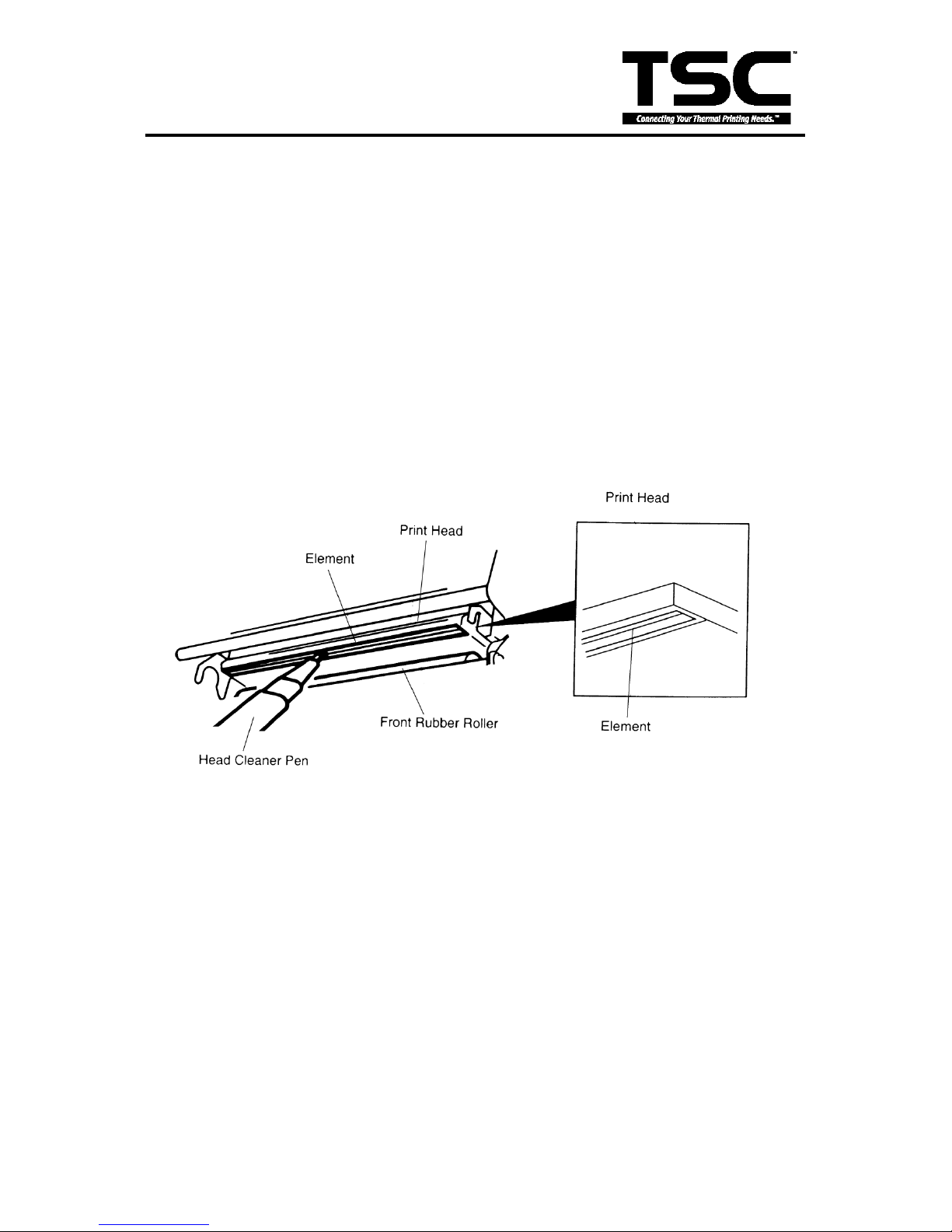
5.8 Cleaning the Print Head
The printer should be cleaned regularly to retain high quality and optimum performance.
The greater the usage of the printer, the more frequent the cleaning.
1. Always turn off the printer before cleaning the print head. Allow the printhead to cool for a
minimum of one minute.
2. Open the printer cover.
3. Open the printer carriage by pulling up the release lever to the left of the front rubber roller.
4. Remove the ribbon and label.
5. Clean the print head element with a head cleaner pen or use a cotton swab and 100% ethanol
to clean the print head surface.
Note:
*Do not touch printer head by hand. If you touch it careless, please use ethanol to clean it.
*It‟s industry alcohol. Please do not use regular alcohol, which may damage the printer head.
Page 55
52
TTP-243 Plus/ 243E Plus/
342 Plus Bar Code Printer
Update History
Date
Content
Editor
2006/4/12
1. Modify to RoHS version.
Camille
2006/6/26
1. Modify the 4-11 item 1-10 : Main board ass'y from
98-0180157-10LF/11LF/12LF to 98-0180157-20LF/21LF/22LF
2. Modify the 3-6 read-time clock circuit figure
Camille
2006/7/24
1.Modify the printer spec.
Camille
2006/8/2
1. Modify the 4-11 item 5-1 : Power adapter from 62-0010021-00LF to
62-0180002-00LF
Camille
2006/8/17
1. Modify the 4-11 item 1-10 : Main board ass'y from
98-0180157-20LF/21LF/22LF to 98-0180157-30LF/31LF/32LF
Camille
2006/8/28
1. Add the 4-11 item 5-5 : External Ethernet print server(Z)
2. Add Gap Sensor in the center part no..
Camille
2006/8/31
1. Modify the 4-11 item 4-2 : PCB-D ass'y from -00LF to -10LF
Camille
2007/1/3
1. Modify the 4-11 item 2-5 : Screw part no. from -31LF to -34LF
2. Modify the 4-11 item 1-12 : Screw part no. from -31LF to -34L
Camille
2007/1/15
1. Modify the 4-11 item 3-6 : Screw part no. from 37-1403015-32LF to
37-1403512-52LF
2. Add power cord/JP part no.
3. Add KP-200, Stand Alone Keyboard Display Unit part no.
Camille
2007/3/1
1. Modify the 4-11 item 1-10 : Main board ass'y from
98-0180157-30LF/31LF/32LF to 98-0180157-40LF/41LF/42LF
Camille
2007/3/9
1. Modify the 4-11 item 5-5 : External Ethernet print server(C) part no.
Camille
2007/4/14
1. Update TSC e-mail address.
2. Update 5.8 section:cleaning the print head.
Camille
2007/8/1
1. Company information update.
Camille
2007/11/8
1. Modify ribbon base assembly part no.
Camille
2007/12/7
1. Modify power supply and external Ethernet print server parts
no./CEC
Camille
2007/12/20
1. Modify PCB-D Ass'y part no.
Camille
2008/1/10
1. Modify part number for label roller mount and memory module cover
2. Revoke part number for 98-1000017-00LF External Ethernet print
server (Z)/US and 98-1000018-00LF External Ethernet print server
(Z)/EU
Camille
2008/1/14
1. Modify description for 98-1000008-01LF External Ethernet print
server (C)/US/CEC and 98-1000009-00LF External Ethernet print
server (C)/EU
Camille
2008/3/18
1. Add lower cover ass‟y (For parallel port) part no.
2. Modify label roller mount part no. from -20LF to -30LF
3. Add power adapter (62-0010021-02LF) /CEC for second source
Camille
2008/6/24
Remove the parts list section
Camille
2011/1/25
Modify TSC address
Camille
Page 56

Corporate Headquarters Li Ze Plant
9F., No.95, Minquan Rd., Xindian Dist., No.35, Sec. 2, Ligong 1st Rd., Wujie Township,
New Taipei City 23141, Taiwan (R.O.C.) Yilan County 26841, Taiwan (R.O.C.)
TEL: +886-2-2218-6789 TEL: +886-3-990-6677
FAX: +886-2-2218-5678 FAX: +886-3-990-5577
Web site: www.tscprinters.com
E-mail: [email protected]
TSC Auto ID Technology Co., Ltd.
 Loading...