

Page 1

TTP-243 Series/243E Series/ 342 Series
USER’S
MANUAL
THERMAL TRANSFER / DIRECT THERMAL BAR
CODE PRINTER
Page 2

Page 3

i
CONTENTS
1. PRODUCT INTRODUCTION ..........................................................2
1.1 Compliances..................................................................................................... 2
2. GETTING STARTED.......................................................................3
2.1 Unpacking and Inspection............................................................................ 3
2.2 Equipment Checklist..................................................................................... 3
2.3 Printer Parts .................................................................................................4
2.4 External Label Roll Mount ............................................................................7
2.5 Buttons and Indicators.................................................................................. 8
3. SET UP............................................................................................9
3.1 Setting Up the Printer................................................................................... 9
3.2 Loading Label and Tag Stock....................................................................... 9
3.3 Self-Peeling Function ................................................................................. 12
3.4 Ribbon Loading Instructions....................................................................... 15
3.5 Install External Label Roll Mount................................................................ 18
3.6 Install Memory Module (Option) ................................................................. 19
3.7 Self Test..................................................................................................... 20
3.8 Dump Mode................................................................................................ 22
4. USING TTP-243 SERIES/243E SERIES/342 SERIES .................23
4.1 Power-on Utilities ....................................................................................... 23
4.1.1 Self Test Utility.................................................................................... 23
4.1.2 Gap Sensor Calibration Utility............................................................. 23
4.1.3 Printer Initialization.............................................................................. 24
4.2 Troubleshooting Guide............................................................................... 25
Page 4

2
1. PRODUCT INTRODUCTION
Thank you very much for purchasing TSC TTP-243 eries/243E series/342 series
bar code printer. The attractive desktop printer delivers superior performance at
an economical price. Both powerful and easy-to-use, this printer is your best
choice among desktop direct thermal and thermal transfer label printers.
Printer offers both thermal transfer and direct thermal printing at selectable
speeds of 1.5, 2.0 and 3.0 inches per second for TTP-243 series/243E series and
1.0, 1.5 and 2.0 inch per second for TTP-342 series. It can accept a wide range
of media, including roll feed, die-cut, and fan-fold labels or tags for both thermal
transfer and direct thermal printing. All of the most frequently used bar code
formats are available. Fonts and bar codes can be printed in any one of four
directions. This printer provides a choice of five different sizes of alphanumeric
fonts. By using font multiplication, an even greater range of sizes is possible.
Smooth fonts can be downloaded from the user-friendly Windows labeling design
software. In addition, This printer is capable of independently executing BASIC
programming functions, including arithmetic, logical operation, loop, flow-control
and file management, among others. This programming capability provides the
greatest efficiency in label printing. The status of printer and error messages may
either be printed out or viewed on a monitor by means of the RS-232 connection.
1.1 Compliances
CE, FCC, TÜV-GS, BSMI, CCC
Page 5

3
2. GETTING STARTED
2.1 Unpacking and Inspection
The printer has been specially packaged to withstand damage in the shipping
process. However, for fear that unexpected damage might occur, upon receiving
the bar code printer, carefully inspect the package and the device. In case of
evident damage, contact the carrier directly to specify the nature and extent of
the damage. Please retain the packaging materials in case you need to reship
the printer.
2.2 Equipment Checklist
One bar code printer unit
One sample roll of plain label stock (Not available for 243E series printer)
One sample roll of wax-resin ribbon (Not available for 243E series printer)
One paper core for ribbon rewind spindle
Two ribbon supply/rewind spindle
One round label supply roll spindle
One label spindle with two fixing tabs
One external label roll mount/spindle (Not available for 243E series printer)
One power supply
One power cord
One Centronics interface cable (Not available for 243E series printer)
One Quick installation guide
One Windows labeling software/Windows driver CD disk
Separately purchased items may also be included. These additional items may
include:
Label
Ribbon
Memory module
Cutter (Not available for 243E series printer)
Peel off module (Not available for 243E series printer)
Portable LCD keyboard
If any parts are missing, please contact the Customer Service Department of
your purchased reseller or distributor.
Page 6
4
2.3 Printer Parts
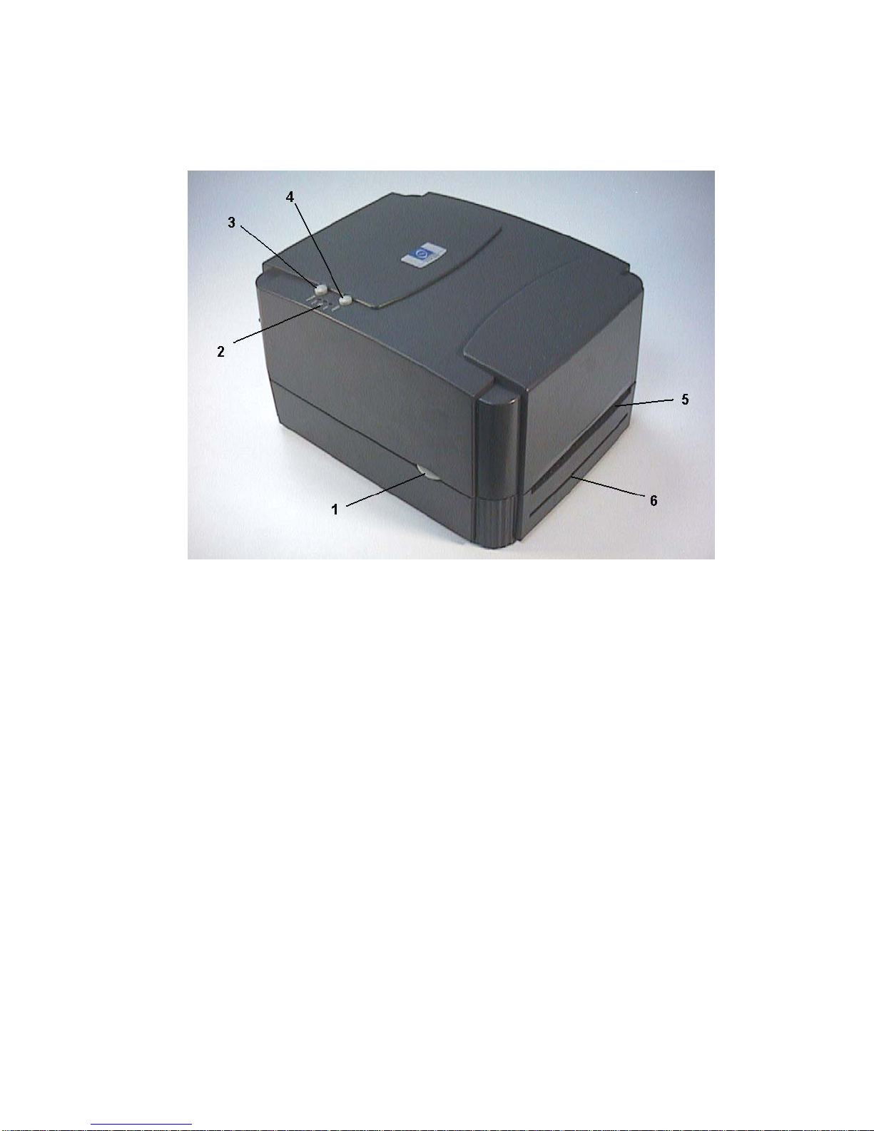
Figure 1. Top front view
1. Cover Release Button
2. PWR., ON-LINE and ERR. Indicators
3. PAUSE Button
4. FEED Button
5. Label Dispense Opening
6. Backing Paper Opening (for use with self-peeling function)
Page 7
5
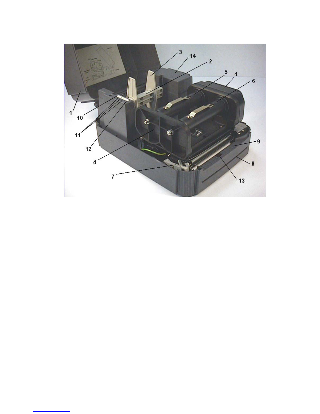
Figure 2. Interior view
1. Printer Cover (in open position)
2. Label Supply Roll Spindle
3. Fixing Tabs
4. Ribbon Mechanism
5. Ribbon Supply Spindle
6. Ribbon Rewind Spindle
7. Printer Carriage Release Lever
8. Backing Paper Opening
9. Detachable Front Panel
10. PAUSE Button
11. PWR., ON-LINE, ERR. Indicators
12. FEED Button
13. Peel-Off Sensor
14. Memory Module Slot (with cover on)
Page 8
6
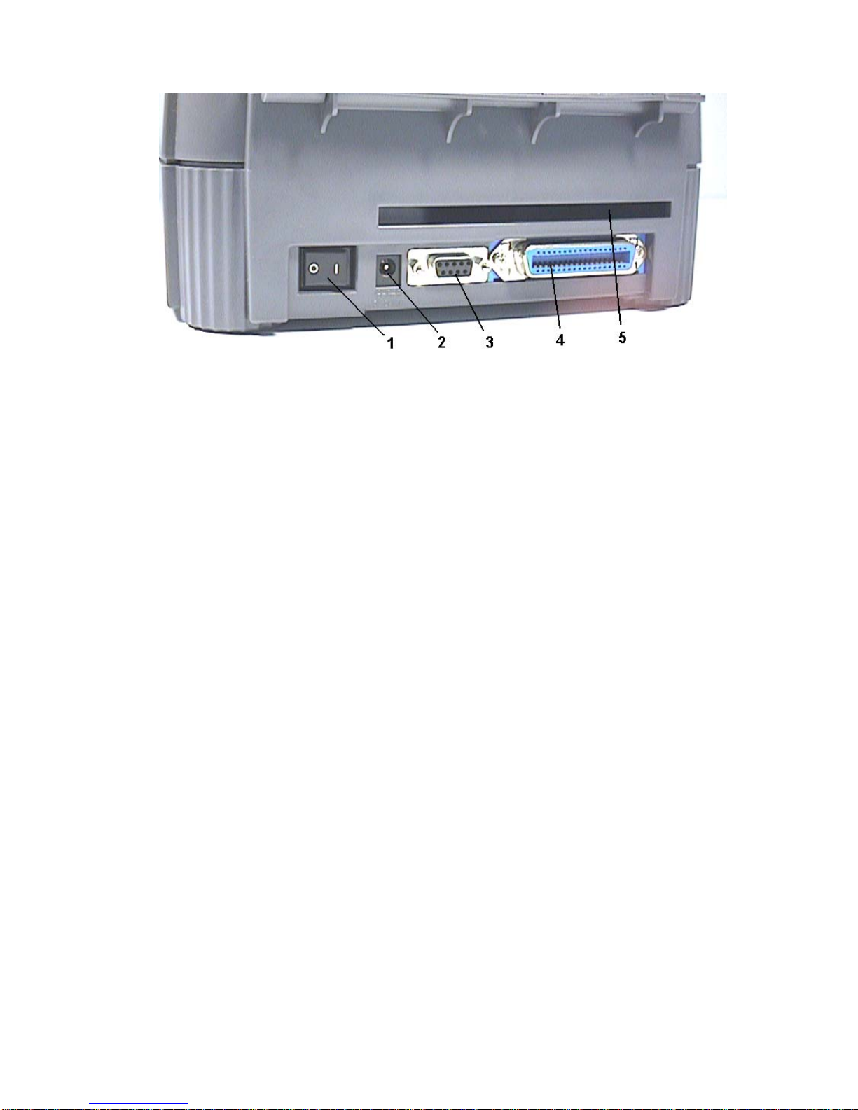
Figure 3. Rear view
1. Power On/Off Switch
2. Power Supply Connector
3. RS-232C DB-9 Interface Connector
4. Centronics Interface Connector
5. Label Insert Opening (for use with external labels)
Page 9
7
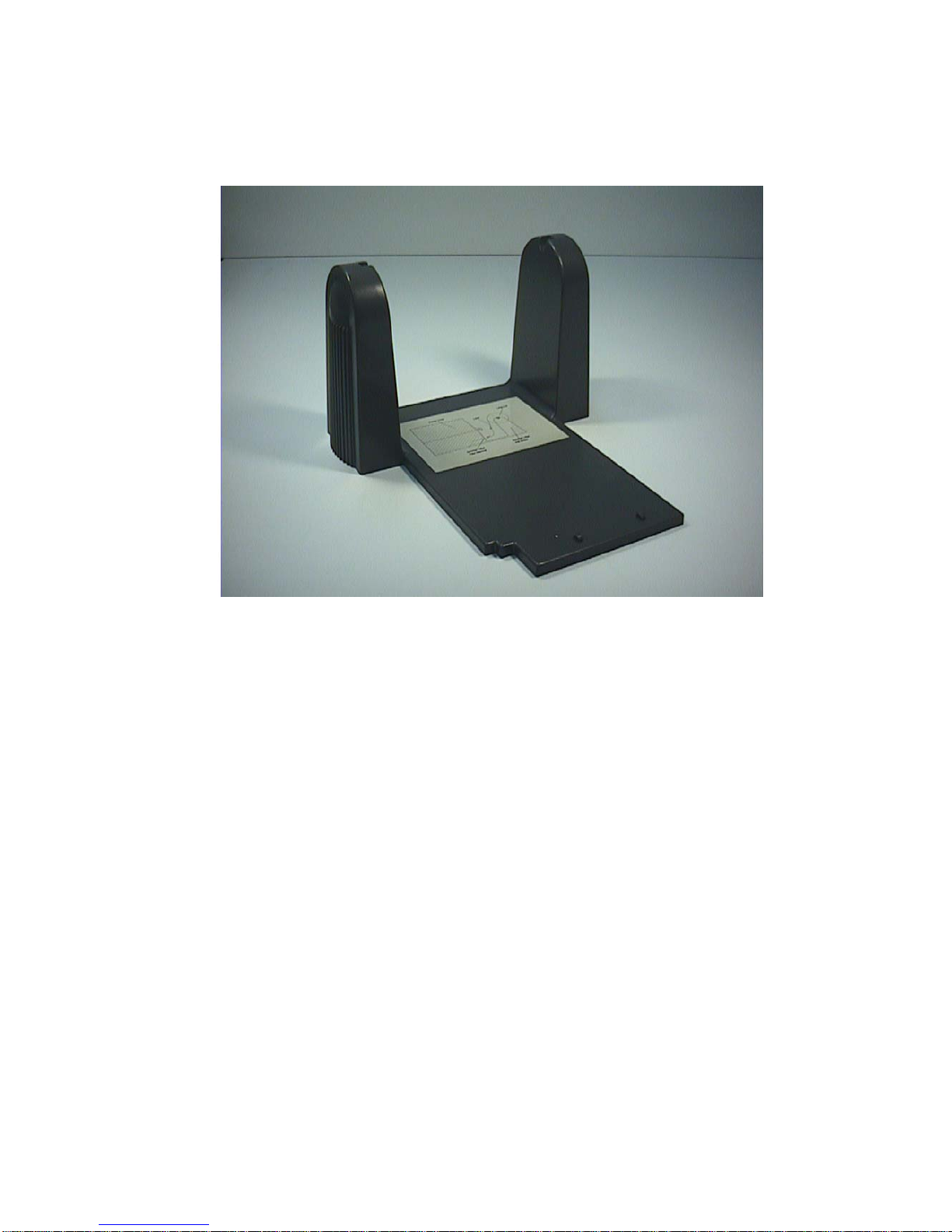
2.4 External Label Roll Mount
Figure 4. External label roll mount
Page 10

8
2.5 Buttons and Indicators
PWR. (POWER) Indicator
The green PWR. indicator illuminates when the POWER switch is turned on.
ON-LINE Indicator
The green ON-LINE indicator illuminates when the printer is ready to print. When
PAUSE button is pressed, the ON-LINE indicator flashes.
ERR. Indicator (Error/Paper Empty)
The red ERR. indicator illuminates in the event of a printer error, such as memory
error, syntax error, and so forth. For a full list of error messages, please refer to
section 4.2, Troubleshooting Guides.
PAUSE Button
The PAUSE button allows the user to stop a print job and then continue the
printing with a second depression of the button. By pressing the PAUSE button:
(1) the printer stops printing after the printing label, (2) the PAUSE LED flashes,
and (3) the printer will hold all data in memory. This allows for trouble-free
replacement of label stock and thermal transfer ribbon. A second depression of
the PAUSE button will restart the printer.
Note: If the PAUSE button is held down for more than 3 seconds, the
printer will be reset and all data of the previous printing job will be lost.
FEED Button
Press the FEED button to feed the label to the beginning of the next label.
Page 11

9
3. SET UP
3.1 Setting Up the Printer
1. Place the printer on a flat, secure surface.
2. Make sure the POWER switch is off.
3. Connect the printer to the computer mainframe with the provided RS-232C or
Centronics cable.
4. Plug the power cord into the power supply connector at the rear of the printer,
and then plug the power cord into a properly grounded receptable.
3.2 Loading Label and Tag Stock
1. Open the printer cover
2. Disengage the printer carriage by pulling the printer carriage release lever on
the left side of the platen.
3. Slide the label supply roll spindle through the core of a label roll and attach the
fixing tabs onto the spindle.
4. Place the label roll into the label roll mount. Feed the label under the carriage
and over the platen.
5. Adjust the label guide to fit the width of the media.
6. Engage the printer carriage.
7. Wind the label roll until it becomes adequately taut.
8. Close the printer cover and press the FEED button three or four times until the
green ON-LINE indicator illuminates.
9. When the printer is out of ribbon or media, the ON-LINE LED will not illuminate
and the ERR. LED will flash. Reload the ribbon or media without turning off the
printer power. Press the FEED button three or four times until the ON-LINE
LED illuminates. The printing job will be resumed without data loss.
Page 12
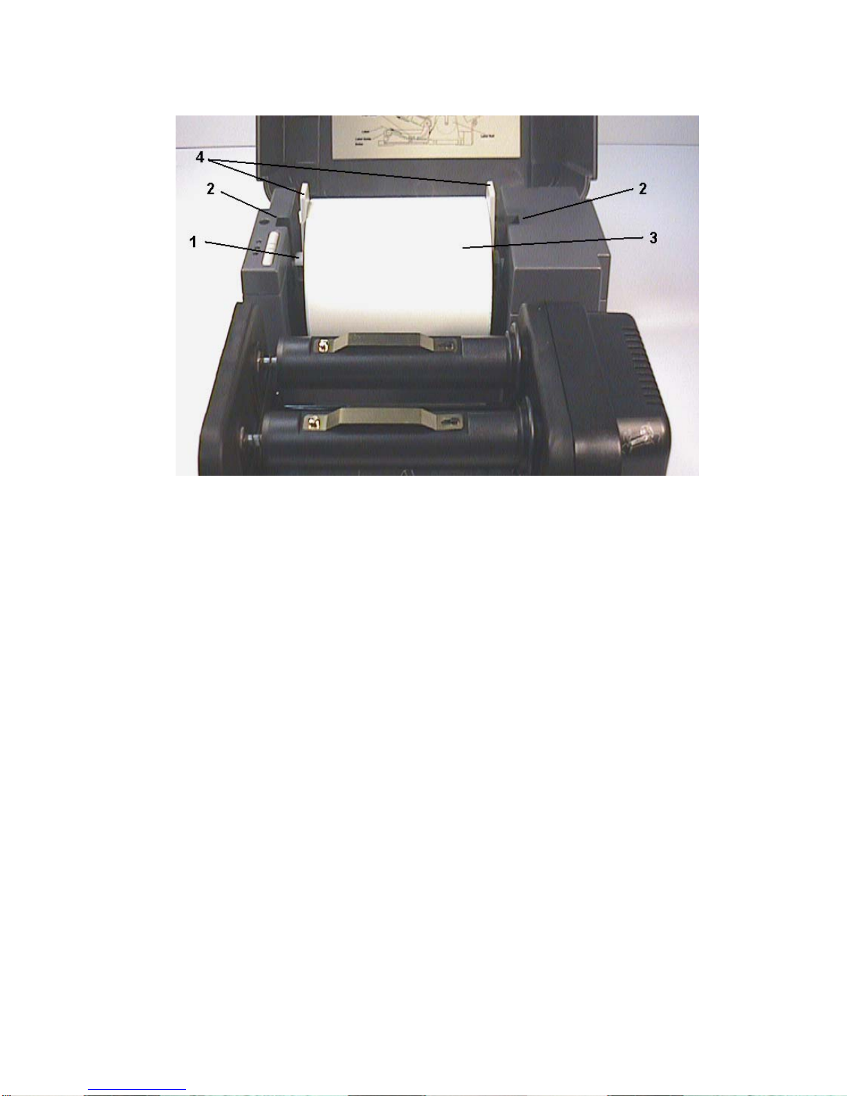
10
Figure 5. Inserting label supply roll into label roll mount
1. Label Supply Roll Spindle
2. Label Roll Mount
3. Label Roll
4. Fixing Tabs
Page 13
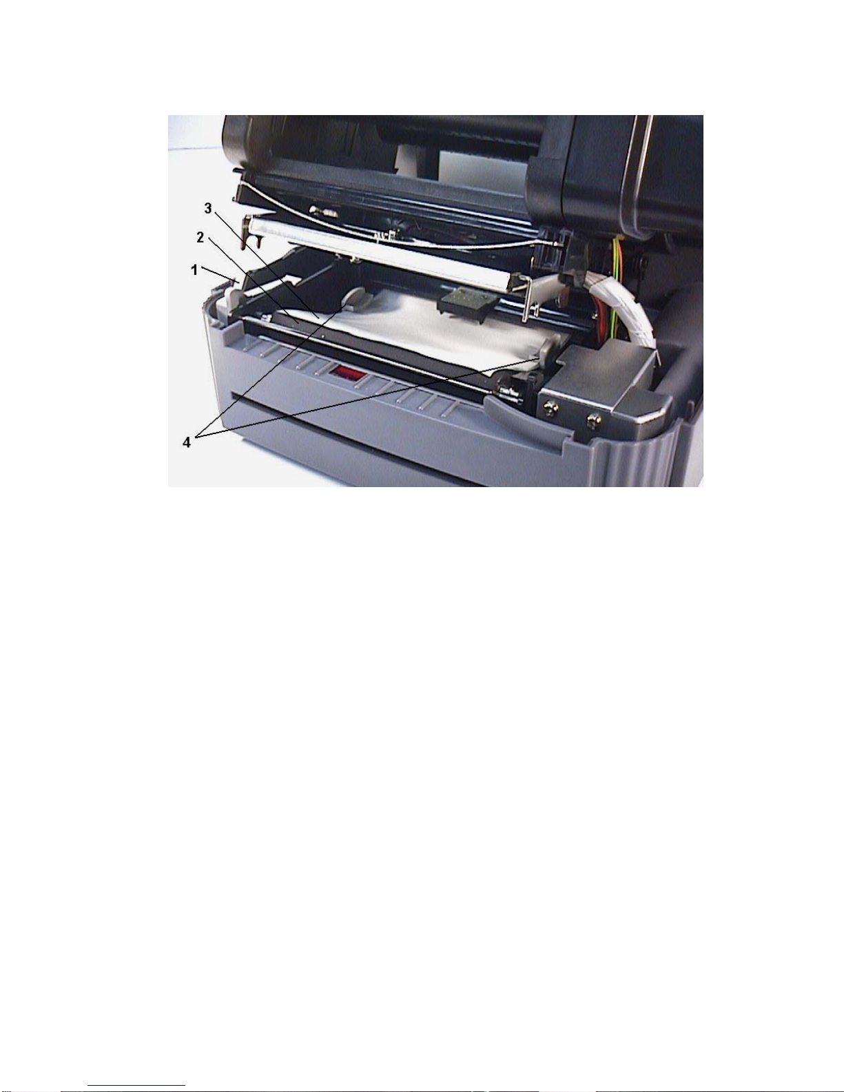
11
Figure 6. Feed labels through adjustable label guide
1. Printer Carriage Release Lever
2. Platen
3. Label Media
4. Adjustable Label Guide
Page 14
12
3.3 Self-Peeling Function
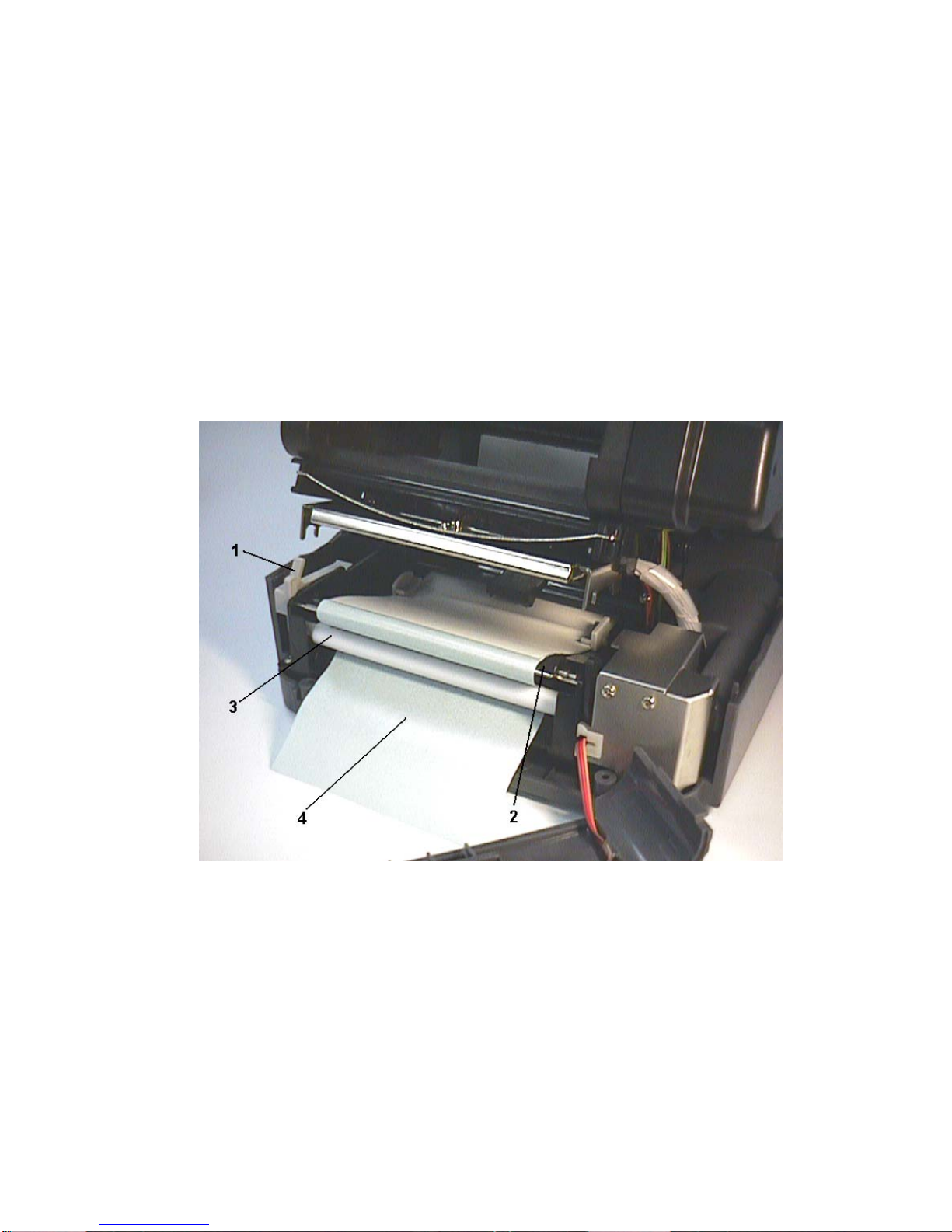
To employ the self-peeling function, load the label stock according to the
following steps.
1. Remove the front panel.
2. Tear off the foremost one or two labels of the label stock, as befits the case.
Feed the backing paper between the platen and the white “self-peeling” roller,
as shown in Figure 7.
3. Feed the backing paper through the backing paper opening in the front panel,
as shown in Figure 8.
4 Put back the front panel.
Figure 7. Setting up printer for self-peeling function
1. Printer Carriage Release Lever
2. Platen
3. Self-Peeling Roller
4. Backing Paper
Page 15

13
Note:
It is recommended that the print speed be set at 2 inches (1.5 inches for
TTP-342 Plus) per second when using the self peeling function of the
printer.
Peel off function is not available for 243E series printer.
Page 16
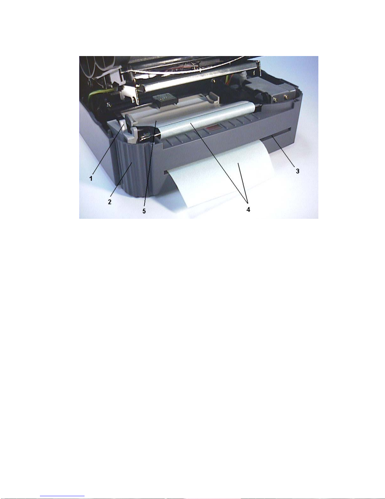
14
Figure 8. Printer ready for self-peeling function
1. Printer Carriage Release Lever
2. Printer Front Panel
3. Backing Paper Opening
4. Backing Paper
5. Label
Note: The 243E series printer is not equipped with the self-peeling device.
Page 17

15
3.4 Ribbon Loading Instructions
1. Place an empty paper core on the ribbon rewind spindle.
2. Install the ribbon on the ribbon supply spindle.
3. Disengage the printer carriage.
4. Pull the ribbon leader to the front from beneath the printer carriage. Attach the
ribbon leader to the ribbon rewind paper core.
5. Rotate the ribbon rewind roller until the ribbon leader is thoroughly, firmly
encompassed by the black section of the ribbon.
6. Engage the printer carriage.
7. Close the printer cover and press the FEED button until the green ON-LINE
LED illuminates.
Note: Please install ribbon and media and close print head mechanism
prior to turn on power. Printer will determine direct thermal or thermal
transfer mode automatically while turning on printer power.
Page 18
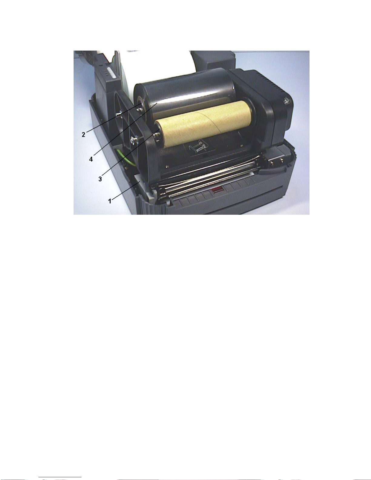
16
Figure 9. Placement of ribbon supply roll
1. Printer Carriage Release Lever
2. Ribbon Supply Spindle
3. Ribbon Rewind Spindle
4. Thermal Transfer Ribbon
Page 19
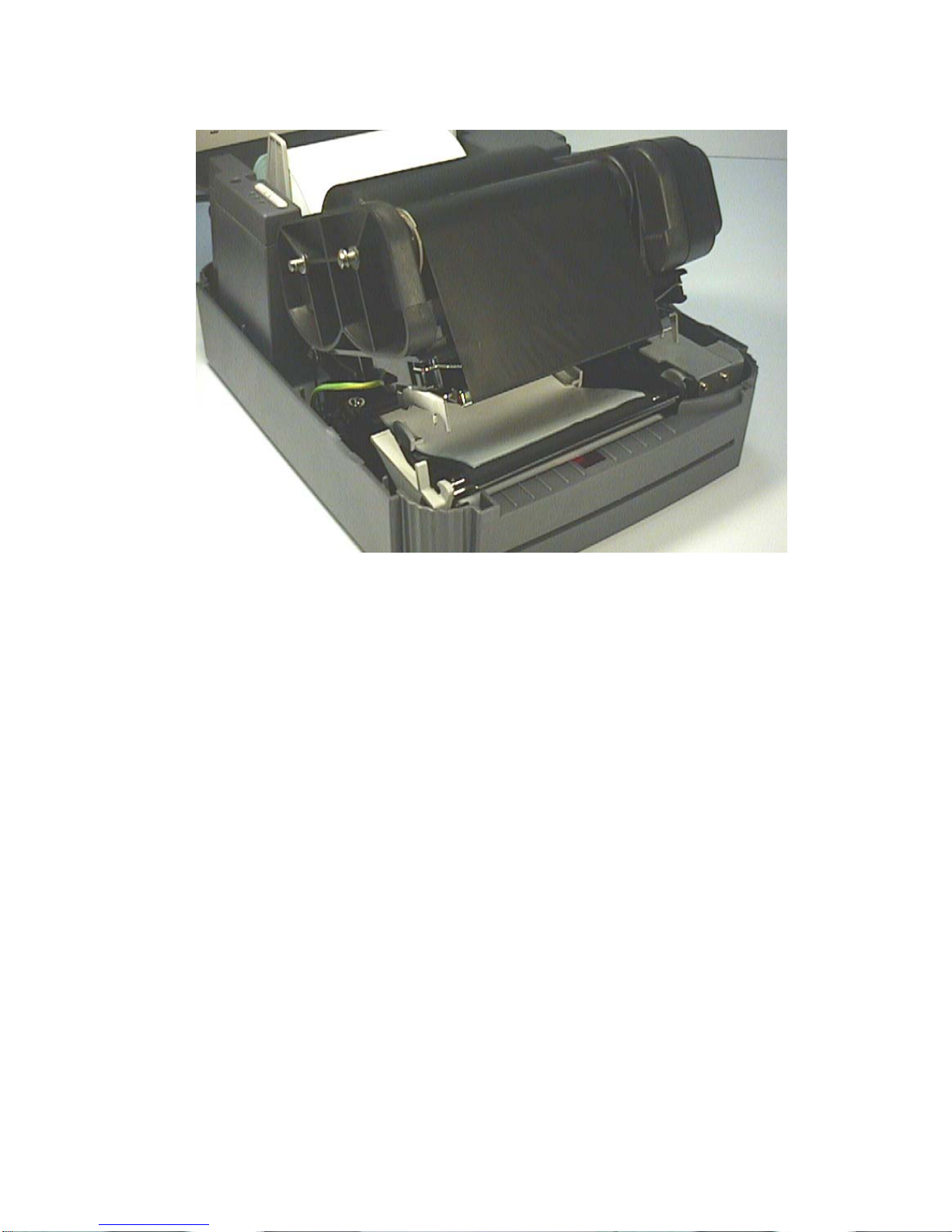
17
Figure 10. Installation of label stock and thermal transfer ribbon
Page 20
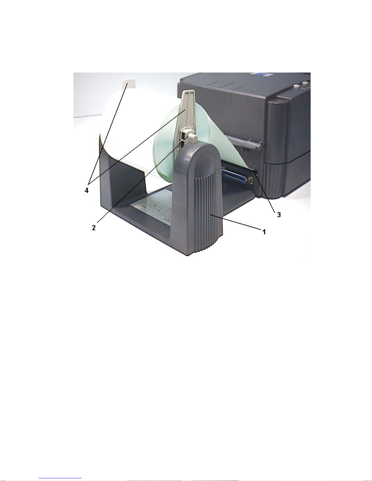
18
3.5 Install External Label Roll Mount
Figure 11. Installation of external label roll mount
1. External Label Roll Mount
2. Label Supply Roll Spindle
3. External Label Feed Opening
4. Fixing Tabs
Page 21
19
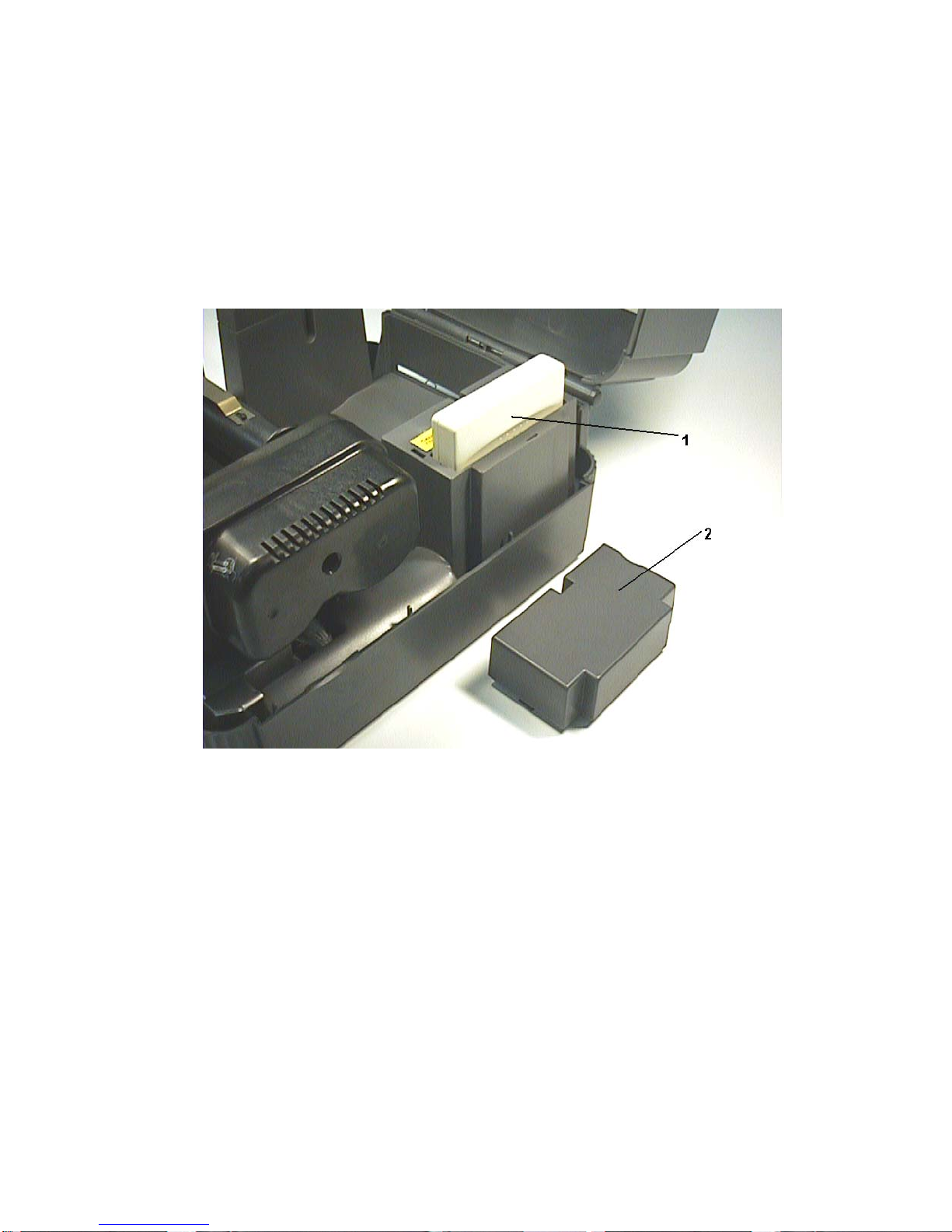
3.6 Install Memory Module (Option)
1. Power off the printer.
2. Remove the cover.
3. Insert the memory module.
4. Put the cover back.
5. Turn on the power
Figure 12. Installation of memory module (Option)
1. Memory Module
2. Cover
Page 22

20
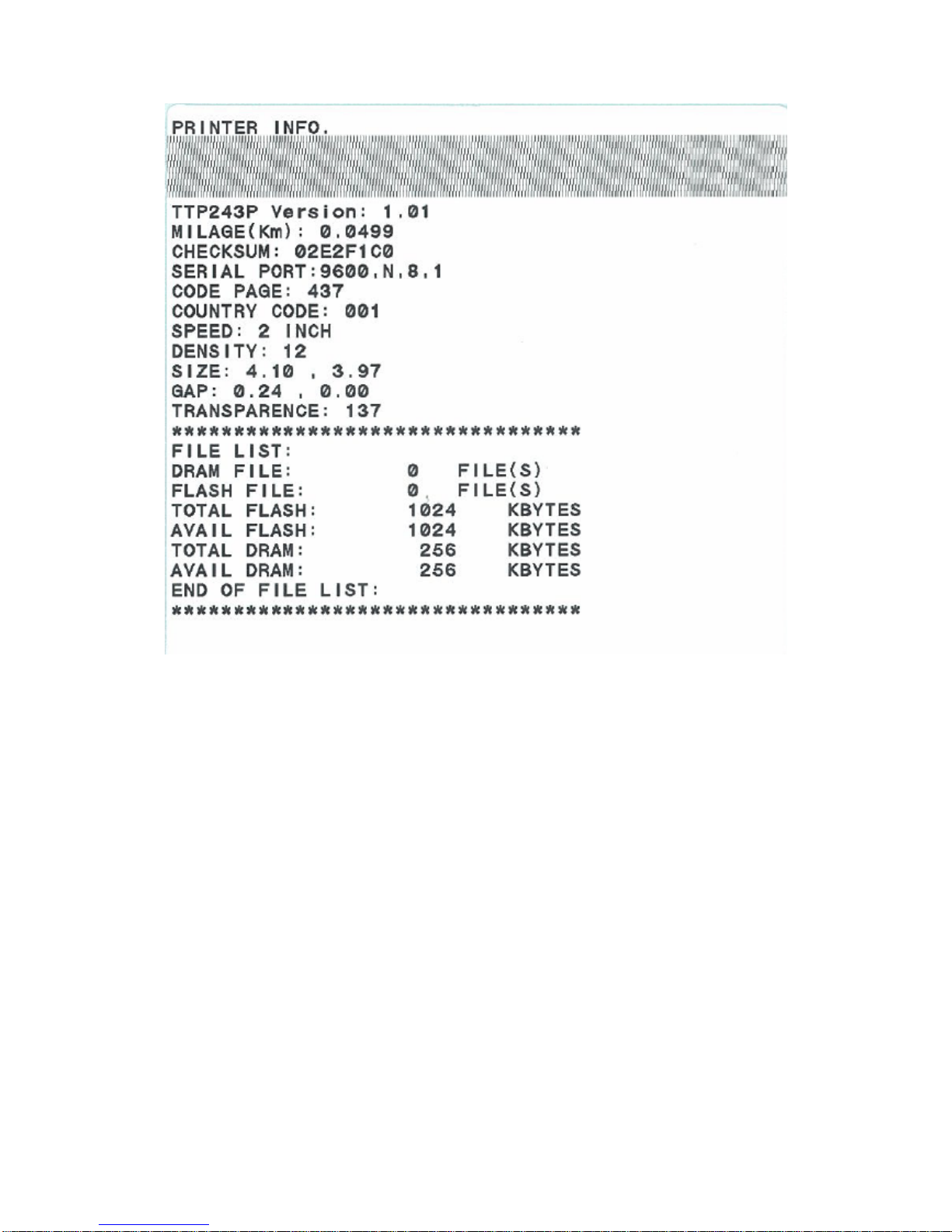
3.7 Self Test
To initiate the self-test mode, depress the FEED button while turning on the
printer power. The printer will calibrate the label length. If the label gap is not
detected within 7", the printer stops feeding labels and the media is treated as
continuous paper. In self test, a check pattern is used to check the performance
of the thermal print head. Following the check pattern, the printer prints internal
settings as listed below:
1. Printer model and firmware version
2. Mileage
3. Check sum
4. Serial port setting
5. Code page setting
6. Country code setting
7. Print speed setting
8. Print density setting
9. Label size setting
10. Gap (Bline) width and offset setting
11. Backing paper transparence
12. File list
13. Available memory space
When the self-test is completed, the printer enters the dump mode. Please turn the
printer's power off and then on to resume normal printing.
Page 23
21
Page 24
22
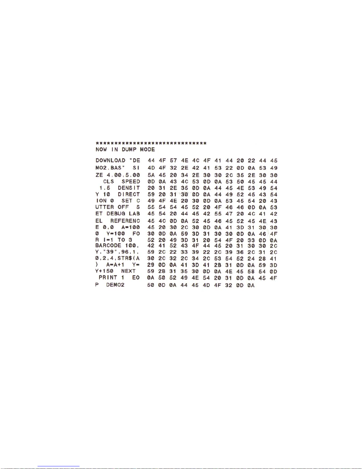
3.8 Dump Mode
After the self-test, the printer enters the dump mode. In this mode, any
characters sent from the host computer will be printed in two columns, as shown.
The characters received will be shown in the first column, and their
corresponding hexadecimal values, in the second. This is often helpful to users
for the verification of programming commands or debugging of printer programs.
Reset the printer by turning the POWER switch off and on.
Page 25

23
4. USING TTP-243 series/243E series/342 series
4.1 Power-on Utilities
There are three power-on utilities to set up and test printer hardware. These
utilities are activated by pressing the FEED or PAUSE button and turning on the
printer power simultaneously. The utilities are listed as below:
1. Self-test
2. Gap sensor calibration
3. Printer initialization
4.1.1 Self Test Utility
Install the label first. Press the FEED button and then turn on the printer power.
Do not release the FEED button until the printer feeds labels. The printer
performs the following items:
1. Calibrate label pitch
2. Print out thermal print head check pattern
3. Print the internal settings
5. Enter dump mode
Regarding the self-test and dump mode, please refer to section 3.7 "Self Test"
and section 3.8 "Dump Mode" for more information.
4.1.2 Gap Sensor Calibration Utility
This utility is used to calibrate the sensitivity of gap sensor. Users may have to
calibrate the gap sensor for two reasons:
1. The media is being changed to a new type.
2. Initialize the printer.
Note: The ERR. LED may flash if gap sensor is not calibrated properly.
Please follow the steps below to calibrate gap sensor:
1. Turn off the printer power and install blank labels (without any logo or
character) on printer.
2. Hold down the PAUSE button then turn on printer power.
3. Release PAUSE button when the printer feeds labels. Do not turn off
printer power until the printer stops and two green LEDs light on.
Note: Black mark sensor has fixed sensitivity. It is no need to calibrate the
black mark sensor
Page 26

24
4.1.3 Printer Initialization
Printer initialization clears all downloaded files resident in flash memory, and sets
printer parameters to default values.
Parameter Default Value
MILEAGE Automatic
CHECK SUM Automatic
SERIAL PORT 9600,N,8,1
CODE PAGE 437 (8 bit), USA (7 bit)
COUNTRY CODE 001
SPEED 2.0”/sec
DENSITY 08
SIZE 4”, 2.5"
GAP (BLINE) 0.12, 0
TRANSPARANCY Will be reset. Need to re-
calibrate the gap sensor
Please follow the steps below to initialize the printer:
1. Turn off the printer power.
2. Hold down the PAUSE and FEED buttons and turn on the printer power.
3. Do not release the buttons until the three LEDs flash in turn.
Note 1: Printing method (thermal transfer or thermal direct printing ) will be
set automatically at the activation of printer power.
Note 2: When printer initialization is done, please calibrate the gap sensor
again.
Note 3: Download files will be deleted after printer initialization.
Page 27

25
4.2 Troubleshooting Guide
The following guide lists some of the most common problems that may be
encountered when operating the bar code printer. If the printer still does not
function after all suggested solutions have been invoked, please contact the
Customer Service Department of your purchased reseller or distributor for
assistance
Problem Solution
Ribbon does not advance or rewind
1. The media and ribbon must be
installed then engage the print head
mechanism prior to turning on
printer power.
2
. Install the black ribbon spindle at the
correct direction.
Poor print quality
1. Clean the thermal print head.
2
. Adjust the print density setting.
3. Ribbon and media are not
compatible.
4
. Media thickness is over spec.
Power indicator does not illuminate
1. Check the power cord, see whether
it is properly connected.
2. Check if the LED on the power
supply is illuminated. If it is not lit
on, then the power supply is
damaged.
ON-LINE indicator is off, ERR.
indicator is on
1. Out of paper or out of ribbon
2. Calibrate the sensitivity of gap
sensor.
3. Ribbon rewind spindle paper core
is not installed.
Continuous feeding when printing
labels
Calibrate the gap sensor.
Page 28

Page 29

Headquarters / Factory
Taipei Office
No. 35, Sec. 2, Ligong 1st Rd., Wujie Town 11F, No. 205, Sec. 3, Beishin Rd., Shindian City,
, I-Lan County, Taiwan 268, R.O.C. Taipei 231, Taiwan, R.O.C.Taiwan 268, R.O.C.
TEL: +886-3-990-6677
TEL: +886-2-8913-1308
FAX: +886-3-990-5577
FAX: +886-2-8913-1808
Web site: www.tscprinters.com
E-mail: [email protected]
TSC Auto ID Technology Co., Ltd.
 Loading...