

F
M
M
Maximum Average Forward Rectified Current
Heatsink.
查询TS10P01G供应商
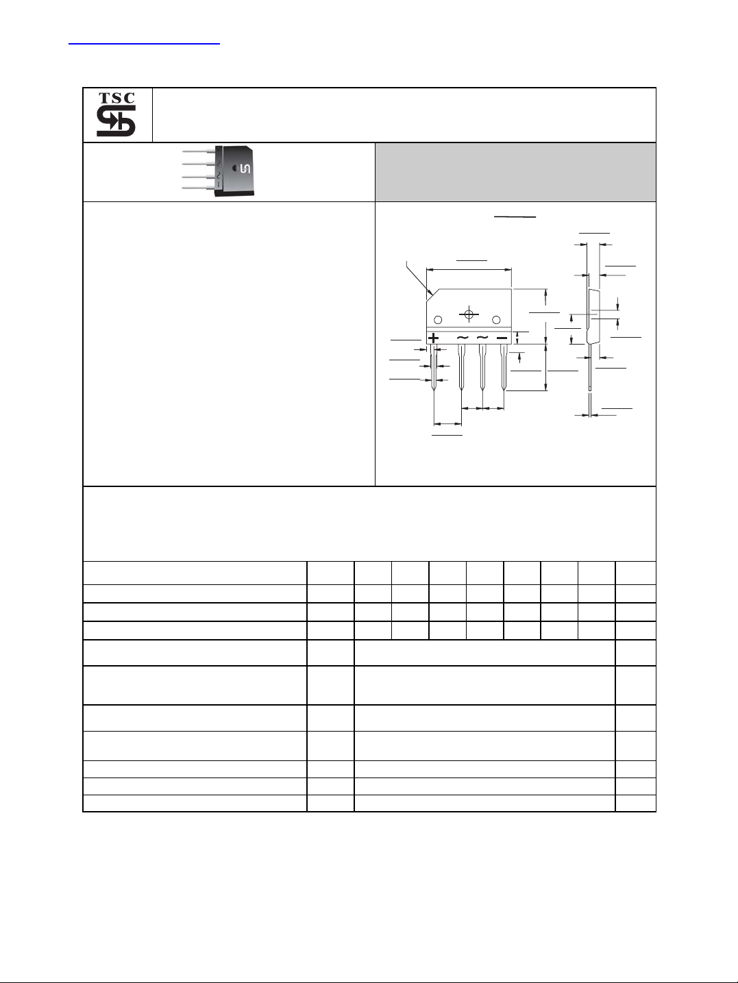
TS10P01G THRU TS10P07G
Single Phase 10.0 Amps. Glass Passivated Bridge Rectifiers
eatures
UL Recognized File # E-96005
Glass passivated junction
Ideal for printed circuit board
Reliable low cost construction
Plastic material has Underwriters Laboratory
Flammability Classification 94V-0
Surge overload rating to 170 amperes peak
High case dielectric strength of 2000V
Isolated voltage from case to lead over 2500
volts
RMS
C .118(3.0)
X45
.106(2.7)
.091(2.3)
.094(2.4)
.079(2.0)
.043(1.1)
.035(0.9)
0
echanical Data
Case: Molded plastic
Terminals: Leads solderable per MIL-
STD-750 Method 2026
Weight: 0.3 ounce,8 grams
Mounting torque: 8.17 in. lbs. max.
.402(10.2)
.386(9.8)
Dimensions in inches and (millimeters)
Voltage Range
50 to 1000 Volts
Current
10.0 Amperes
TS-6P
1.193(30.3)
1.169(29.7)
.189(4.8)
.165(4.2)
.150(3.8)
.303
(7.7)
.287
(7.3)
.303
(7.7)
.287
(7.3)
.799(20.3)
.776(19.7)
.441(11.2)
.425(10.8)
.709(18.0)
.669(17.0)
.189(4.8)
.173(4.4)
.150(3.8)
.134(3.4)
.134(3.4)
.122(3.1)
.114(2.9)
.098(2.5)
.031(0.7)
.024(0.6)
aximum Ratings and Electrical Characteristics
Rating at 25℃ambient temperature unless otherwise specified.
Single phase, half wave, 60 Hz, resistive or inductive load.
For capacitive load, derate current by 20%
Type Number
Maximum Recurrent Peak Reverse Voltage
Maximum RMS Voltage
Maximum DC Blocking Voltage
See Fig. 2
Peak Forward Surge Current, 8.3 ms Single
Half Sine-wave Superimposed on Rated
Load (JEDEC method )
Maximum Instantaneous Forward Voltage
@ 10.0A
Maximum DC Reverse Current @ TA=25℃
at Rated DC Blocking Voltage @ TA=125℃
Typical Thermal Resistance (Note)
Operating Temperature Range T
Storage Temperature Range T
Note: Thermal Resistance from Junction to Case with Device Mounted on 4” x 6” x 0.25” Al-Plate
Symbol
V
V
RRM
RMS
V
I
(AV)
I
FSM
VF
IR
R
TS10P
TS10P
TS10P
TS10P
TS10P
01G
02G
03G
04G
05G
TS10P
06G
50 100 200 400 600 800 1000 V
35 70 140 280 420 560 700 V
50 100 200 400 600 800 1000 V
DC
10.0 A
200 A
1.1 V
5.0
500
θ
STG
JC
J
1.4
-55 to +150
-55 to + 150
TS10P
07G
Units
uA
uA
℃/W
℃
℃
- 758 -
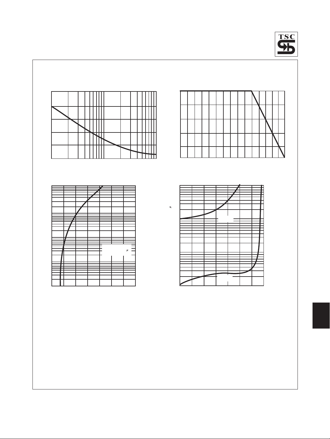
RATINGS AND CHARACTERISTIC CURVES (TS10P01G THRU TS10P07G)
FIG.1- MAXIMUM NON-REPETITIVE FORWARD SURGE
CURRENT PER BRIDGE ELEMENT
250
200
150
100
50
PEAK FORWARD SURGE CURRENT. (A)
0
1
2 10 20 100505
NUMBER OF CYCLES AT60Hz
FIG.3- TYPICAL INSTANTANEOUS FORWARD
CHARACTERISTICS PER BRIDGE ELEMENT
100
10
1
o
Tj=25 C
Pulse Width=300 s
1% Duty Cycle
0.1
INSTANTANEOUS FORWARD CURRENT. (A)
0.01
0.6
0.8 1.0 1.2 1.4 1.6 1.8 2.0
FORWARD VOLTAGE. (V)
FIG.2- MAXIMUM FORWARD CURRENT DERATING
CURVE
10
8
6
4
2
AVERAGE FORWARD CURRENT. (A)
0
0
FIG.4- TYPICAL REVERSE CHARACTERISTICS
PER BRIDGE ELEMENT
100
10
1
INSTANTANEOUS REVERSE CURRENT.( A)
0.1
0
20 40 60 80 100 120 140
PERCENT OF RATED PEAK REVERSE VOLTAGE. (%)
50
CASE TEMPERATURE. ( C)
0
Tj=125 C
0
Tj=25 C
100
o
150
- 759 -

All Datasheets cannot be modified without permission.
This datasheet has been download from :
www.AllDataSheet.com
100% Free DataSheet Search Site.
Free Download.
No Register.
Fast Search System.
www.AllDataSheet.com
 Loading...