

Page 1

i
USER’S
MANUAL
TE200/TE300 Series
THERMAL TRANSFER/DIRECT THERMAL BAR
CODE PRINTER
Page 2

ii
Copyright Information
©2016 TSC Auto ID Technology Co., Ltd,
The copyright in this manual, the software, and firmware in the printer described
therein are owned by TSC Auto ID Technology Co., Ltd, All rights reserved.
CG Triumvirate is a trademark of Agfa Corporation. CG Triumvirate Bold
Condensed font is under license from the Monotype Corporation. Windows is a
registered trademark of Microsoft Corporation.
All other trademarks are the property of their respective owners.
Information in this document is subject to change without notice and does not
represent a commitment on the part of TSC Auto ID Technology Co. No part of
this manual may be reproduced or transmitted in any form or by any means, for
any purpose other than the purchaser’s personal use, without the expressed
written permission of TSC Auto ID Technology Co.
Page 3

iii
Agency Compliance and Approvals
EN 55032, Class A
EN 55024
EN 60950-1
This is a class A product. In a domestic environment this product may cause
radio interference in which case the user may be required to take adequate
measures.
FCC part 15B, Class A
ICES-003, Class A
This equipment has been tested and found to comply with the limits for a
Class A digital device, pursuant to Part 15 of the FCC Rules. These limits
are designed to provide reasonable protection against harmful interference
when the equipment is operated in a commercial environment.
This equipment generates, uses, and can radiate radio frequency energy
and, if not installed and used in accordance with the manufacturer’s
instruction manual, may cause harmful interference with radio
communications. Operation of this equipment in a residential area is likely to
cause harmful interference, in which case you will be required to correct the
interference at your own expense.
This Class A digital apparatus complies with Canadian ICES-003.
Cet appareil numérique de la classe A est conform à la norme NMB-003 du
Canada.
This device complies with Part 15 of the FCC Rules. Operation is subject to
the following two conditions: (1) This device may cause harmful
interference, and (2) this device must accept any interference received,
including interference that may cause undesired operation.
AS/NZS CISPR 32, Class A
UL 60950-1(2nd Edition)
CSA C22.2 No. 60950-1-07(2nd Edition)
EN 60950-1
GB 4943.1
GB 9254, Class A
GB 17625.1
此为 A 级产品,在生活环境中,该产品可能会造成无线电干扰,
在这种情况下,可能需要用户对干扰采取切实可行的措施。
Energy Star for Imaging Equipment Version 2.0
Page 4

iv
TP TC 004/2011
TP TC 020/2011
IS 13252(Part 1)/
IEC 60950-1
R-41055980
KN 32
KN 35
Important safety instructions:
1. Read all of these instructions and keep them for later use.
2. Follow all warnings and instructions on the product.
3. Disconnect the power plug from the AC outlet before cleaning or if fault happened.
Do not use liquid or aerosol cleaners. Using a damp cloth is suitable for cleaning.
4. The mains socket shall be installed near the equipment and easily access ibl e.
5. The unit must be protected against moisture.
6. Ensure the stability when installing the device, Tipping or dropping could cause damage.
7. Make sure to follow the correct power rating and power type indicated on marking label
provided by manufacture.
8. Please refer to user manual for maximum operation ambient temperature.
WARNING:
Hazardous moving parts, keep fingers and other body parts away.
CAUTION:
(For equipment with RTC (CR2032) battery or rechargeable battery pack)
Risk of explosion if battery is replaced by an incorrect type.
Dispose of used batteries according to the Instructions as below.
1. DO NOT throw the battery in fire.
2. DO NOT short circuit the contacts.
3. DO NOT disassemble the battery.
4. DO NOT throw the battery in municipal waste.
5. The symbol of the crossed out wheeled bin indicates that the ba ttery should not be
placed in municipal waste.
Caution: The printhead may be hot and could cause severe burns. Allow the
printhead to cool.
Page 5

v
Contents
1. Introduction ..........................................................................................................1
1.1 Product Introduction ..................................................................................... 1
1.2 Product Features ........................................................................................... 2
1.2.1 Printer Standard Features .................................................................. 2
1.2.2 Printer Optional Features ................................................................... 3
1.3 General Specifications .................................................................................. 4
1.4 Print Specifications ........................................................................................4
1.5 Ribbon Specifications ....................................................................................4
1.6 Media Specifications ......................................................................................5
2. Operations Overview ...........................................................................................6
2.1 Unpacking and Inspection ............................................................................ 6
2.2 Printer Overview ............................................................................................ 7
2.2.1 Front View ............................................................................................ 7
2.2.2 Interior View ........................................................................................ 8
2.2.3 Rear View ............................................................................................. 9
3. Setup ................................................................................................................... 10
3.1 Setting up the Printer .................................................................................. 10
3.2 Loading the Ribbon ..................................................................................... 11
3.3 Loading the Media ....................................................................................... 14
3.3.1 Loading the Roll Labels .................................................................... 14
3.3.2 External Label Roll Mount Installation (Option) .............................. 17
4. LED and Button Functions ............................................................................... 18
4.1 LED Indicator ............................................................................................... 19
4.2 Regular Button Functions ........................................................................... 19
4.3 Power-on Utilities ........................................................................................ 19
4.3.1 Gap/Black Mark Sensor Calibration ................................................. 20
4.3.2 Gap/Black Mark Calibration, Self-test and Dump Mode.................. 21
4.3.3 Printer Initialization ........................................................................... 24
4.3.4 Set Black Mark Sensor as Media Sensor and Calibrate the Black
Mark Sensor ................................................................................................... 25
4.3.5 Set Gap Sensor as Media Sensor and Calibrate the Gap Sensor .. 25
4.3.6 Skip AUTO.BAS ................................................................................. 26
5. Diagnostic Tool .................................................................................................. 27
5.1 Start the Diagnostic Tool ............................................................................ 27
5.2 Printer Function ........................................................................................... 28
Page 6

vi
5.3 Calibrating Media Sensor by Diagnostic Tool ............................................ 29
5.3.1 Auto Calibration ................................................................................ 29
6. Troubleshooting ................................................................................................. 30
6.1 Common Problems ...................................................................................... 30
7. Maintenance ....................................................................................................... 31
Revise History ........................................................................................................ 32
Page 7

1
1. Introduction
1.1 Product Introduction
Thank you very much for purchasing TSC bar code printer.
The TE200/TE300 series printer features the single motor that is capable of handling a large
capacity of 300 meters ribbon and large rolls of media inside its sleek design. If the 5” interior
label capacity is not enough, simply add an external media roll mount and the TE200/TE300
series can easily handle 8” OD rolls of labels designed for expensive industrial label printers.
The movable black mark sensor design can accept a wide range of label media. All of the most
frequently used bar code formats are included. Fonts and ba r codes can be printed i n any one o f
the four directions.
The TE200/TE300 series printer is built-in the high quality, high-performance MONOTYPE
IMAGING
®
True Type font engine and one CG Triumvirate Bold Condensed smooth font. With
flexible firmware design, user can also download the True Type Font from PC into printer
memory for printing labels. Besides the scalable font, it also provides a choice of eight different
sizes of the alphanumeric bitmap font. By integrating rich features, it is the most cost-effective
and high-performance printer in its class!
To print label formats, please refer to the instructions provi ded with your labeling software; if you
need to write the custom programs, please refer to the TSPL/TSPL2 programming manual that
can be found on TSC website at http://www.tscprinters.com.
• Applications
o Manufacturing & Warehousing
Work i n Progres s
Item Labels
Instruction labels
Agency labels
o Healthcare
Patient Identification
Pharmacy
Specimen Identification
o Parcel Post
Shipping/ Receiving
Labels
o Small Office/ Home Office
o Retail Marking
Price tags
Shelf labels
Jewelry tags
Page 8

2
1.2 Product Features
1.2.1 Printer Standard Features
The prin ter offers the following standard features.
Product standard feature
TE200
(203 dpi
model)
TE300
(300 dpi
model)
Thermal transfer printing
○ ○
Direct thermal printing
○ ○
Plastic
○ ○
Gap sensor
○ ○
Reflective, full-range moveable black mark sensor
○ ○
Ribbon sensor
○ ○
Head open sensor
○ ○
USB 2.0 (hi-speed) interface
○ ○
16 MB DRAM memory
○ ○
8 MB Flash memory
○ ○
SD card reader (R
eserve a PIN connector for updating
firmware by card when maintenance.)
- -
One button for feed and pause
○ ○
One LED indicator for 3 colors
○ ○
Standard industry emulations right out of the box including
Eltron® and Zebra® language support
○ ○
Internal 8 alpha-numeric bitmap fonts
○ ○
Fonts and bar codes can be printed in any one of the four
directions (0, 90,180, 270 degrees)
○ ○
Internal Monotype Imaging® true type font engine with one
CG Triumvirate Bold Condensed scalable font
○ ○
Downloadable fonts from PC to printer memory
○ ○
Downloadable firmware upgrades
○ ○
Page 9

3
Text, bar code, graphics/image printing (Please refer to the
TSPL/TSPL2 programming manual for supporting code
page)
Supported bar code
Supported image
1D bar code
2D bar code
BITMAP,
BMP,
PCX
(Max. 256 colors
graphics)
Code128UCC,
Code128 subsets
A、B、
C, EAN128,
Interleaved 2 of 5,
Interleaved 2 of 5
with check digit,
Code39, Code39
with check digit,
Code93, EAN13,
EAN8, UPCA,
UPCE, EAN and
UPC 2 (5) digits
add-
on, Codabar,
Postnet, MSI, MSI
with check digit,
PLESSEY, China
post, ITF14,
Code11, TELEPEN,
TELEPENN,
PLANET, Code49,
Deutsche Post
Identcode, Deutsche
Post Leitcode,
LOGMARS
GS1 DataBar,
GS1
DataMatrix,
Maxicode,
AZTEC,
PDF417, QR
Code, Micro
PDF 417
○ ○
1.2.2 Printer Optional Features
The printer offers the following optional features.
Product option feature
User
options
Dealer
options
Factory
options
Extended plate for external roll mount assembly with
3” core label spindle (8.4 OD)
○
- -
Internal Bluetooth v4.0 - -
○
Page 10

4
1.3 General Specifications
General Specifications
Physical dimensions
204 mm (W) x 164 mm (H) x 280 mm (L)
Weight 2.4 kg
Electrical External universal switching power supply
Input: AC 100-240V, 2A, 50-60 Hz
Output: DC 24V, 2.5A, 60W, LPS
Environmental condition Operation: 5 ~ 40˚C (41 ~ 104˚F), 25~85% non-condensing
Storage: -40 ~ 60 ˚C (-40 ~ 140˚F), 10~90% non-condensing
1.4 Print Specifications
Print Specifications TE200 (203 dpi model) TE300 (300 dpi model)
Print head resolution 203 dots/inch (8 dots/mm) 300 dots/inch (12 dots/mm)
Printing method Thermal transfer and direct thermal
Dot size
(width x length)
0.125 x 0.125 mm
(1 mm = 8 dots)
0.084 x 0.084 mm
(1 mm = 11.8 dots)
Print speed
(inches per second)
Up to 6 ips Up to 5 ips
Print speed for peel
mode & cutter mode
N/A
Max. print width 108 mm (4.25”) 105.6 mm (4.16”)
Max. print length 2,794 mm (110”) 1,016 mm (40”)
1.5 Ribbon Specifications
Ribbon Specifications
Ribbon outside diameter 1” core: Max. 67mm
0.5” core: Max. 40mm
Ribbon length 1” inner core: 300 meters
0.5” inner core: 110 meters
Ribbon core inside diameter 0.5 and 1 inch
Ribbon width 40 ~ 110 mm (with 110 mm paper core and notches on
both sides)
Ribbon wound type Outside wound
Page 11

5
1.6 Media Specifications
Media Specifications
TE200
(203 dpi model)
TE300
(300 dpi model)
Label roll capacity 5” OD, 75m
Media type
Continuous, die-cut, black mark, fan-fold, notch
Media wound type Outside wound
Media width 20mm ~ Max. 112 mm
Media thickness 0.06 mm (2.36 mil) ~ 0.19 mm (7.48 mil)
Media core diameter 1” (25.4 mm) & 1.5” (38 mm) ID core
Tear mode 50 mm ~ Max. print length
Note: Media can be torn at the same direction.
Label length 10 mm ~ Max. printing length
Label length (peeler mode) N/A
Label length (cutter mode) N/A
Gap height Min. 2 mm (0.09”)
Black mark height Min. 2 mm (0.09”)
Black mark width Min. 8 mm (0.31”)
Page 12

6
2. Operations Overview
2.1 Unpacking and Inspection
This printer has been specially packaged to withstand damage during shipping. Please carefully
inspect the packaging and printer upon receiving the bar code printer. Please retain the
packaging materials in case you need to reship the printer.
Unpacking the printer, the following items are included in the carton.
One printer unit
One quick installation guide
One power cord
One external universal switching power supply
One USB interface cable
A pair of 1” Ribbon spindles for 300M ribbon
One 1’’ ribbon paper core
One label spindle with two wings and two 1.5” adapters
If any parts are missing, please contact the Customer Service Department of your purchased
reseller or distributor.
Page 13
7
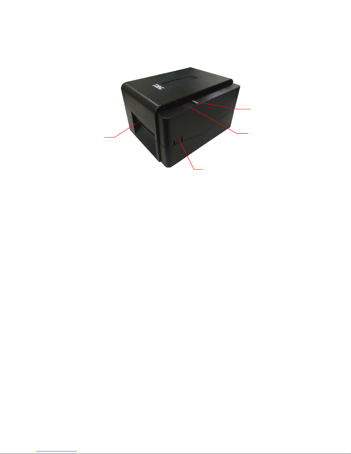
2.2 Printer Overview
2.2.1 Front View
1. LED indicator
2. Feed/Pause button
3. Top cover open tab
4. Paper exit chute
1
2
4
3
Page 14
8
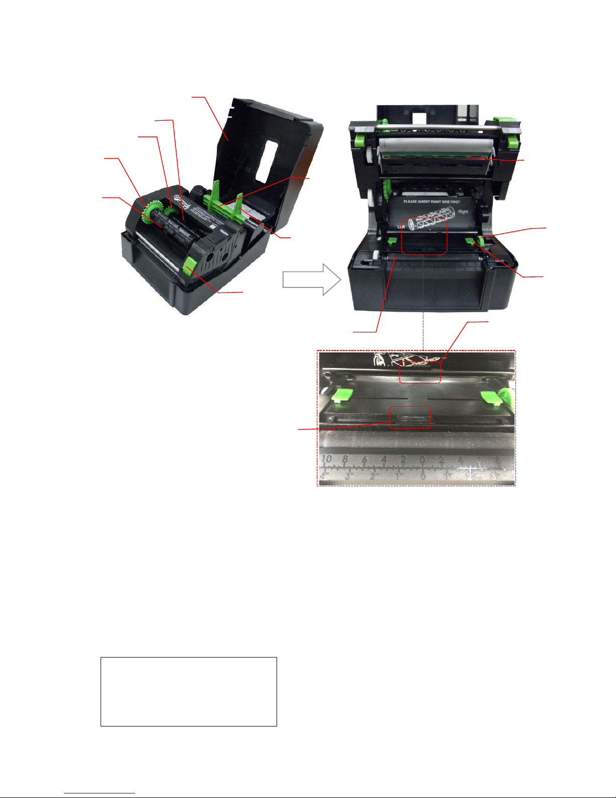
2.2.2 Interior View
1.
Printer top cover
8.
Media supply spindle
2.
Ribbon supply spindle
9.
Platen roller
3.
Ribbon supply hub
10.
Black mark sensor/Gap sensor (receiver)
4.
Ribbon rewind hub
11.
Gap sensor (transmitter)
5.
Ribbon rewind spindle
12.
Media guide
6.
Print head release button
13.
Media guide hub
7.
Fixing tab
14.
Print head
WARNING
HAZARDOUS MOVING PARTS
KEEP FINGERS AND OTHER
BODY PARTS AWAY
OPEN
7
6
1
4
5
8
13
12
14
9
11
10
2
3
Page 15
9
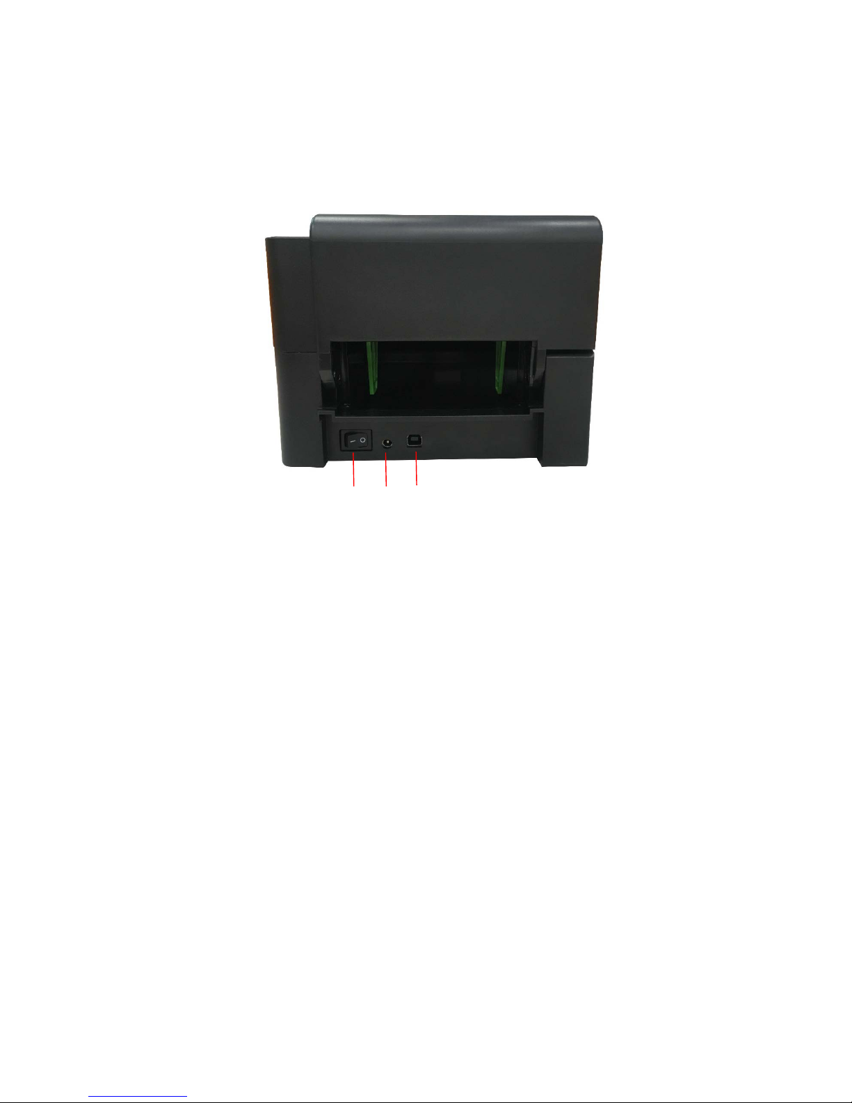
2.2.3 Rear View
1. Power switch
2. Power jack socket
3. USB interface (USB 2.0/Full speed mode)
Note:
The interface picture here is for reference only. Please refer to the product specification for
the interfaces availability.
1 2
3
Page 16
10
3. Setup
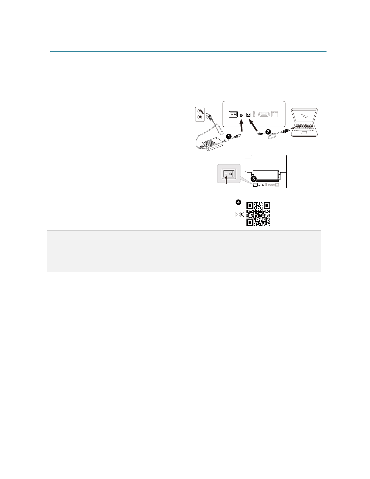
3.1 Setting up the Printer
Place the printer on a flat, secure surface, then
follow the steps below:
1. Plug the power cord into the AC power cord
socket at the rear of the printer. Then, plug
the other side into a properly grounded
power outlet.
2. Connect the printer to the computer with the
provided USB cable.
3. Push the power switch on “-
” side to open the
power of printer.
4. If you would like to watch printer installation
videos, please scan the QR code on the
right
side for more information.
Note:
* Please switch OFF printer power switch prior to plugging in the power cord to printer power jack.
* The interface picture here is for reference only. Please refer to the product specification for the interfaces
availability.
Page 17
11
3.2 Loading the Ribbon
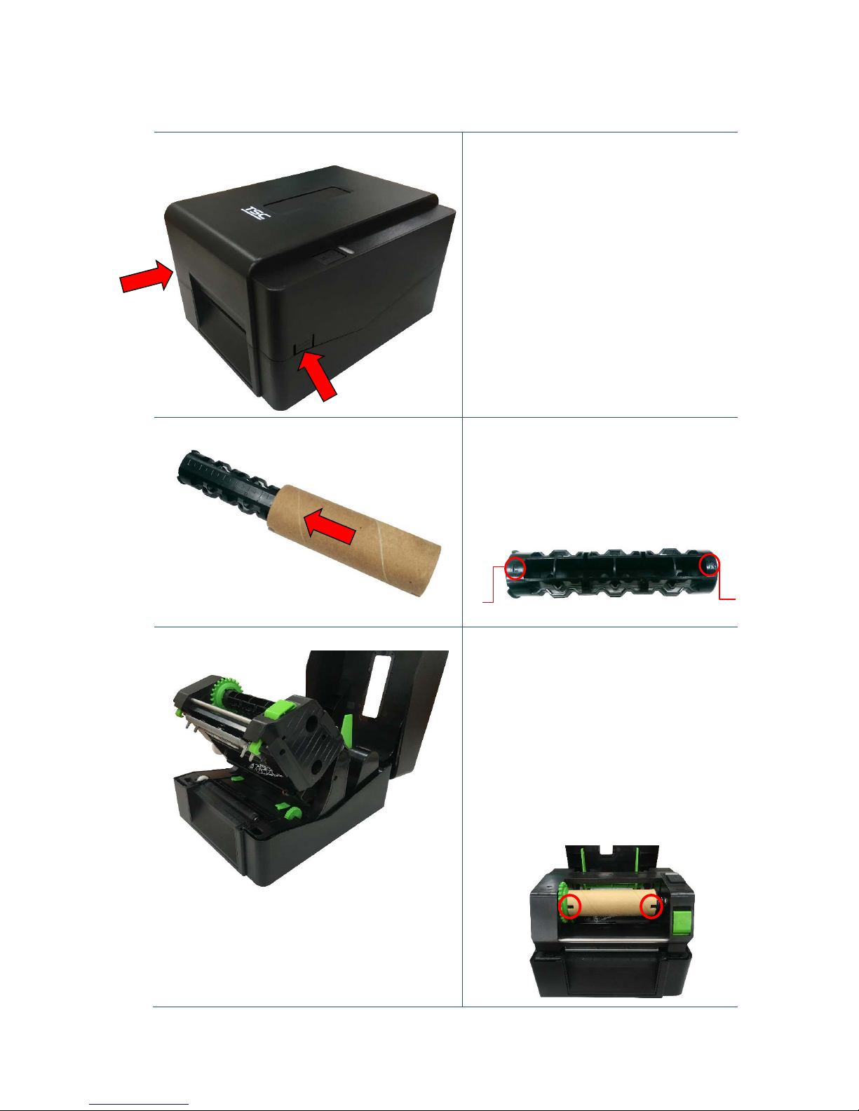
1. Open the printer top cover by
pressing the top cover open tabs
located on each side of the printer.
2. Insert the paper core to the ribbon
rewind spindle.
Note: Please follow the direction
when installing the ribbon rewind
spindle.
3. Insert the right side of ribbon rewind
spindle to ribbon rewind hub first.
Then, insert the left side to the hole
at the left side of ribbon mechanism.
Note:
It can also be substituted by 0.5 or
1 inch paper roll with notches on
both sides. Please insert it at the
ribbon rewind hub directly.
R
L
Page 18
12
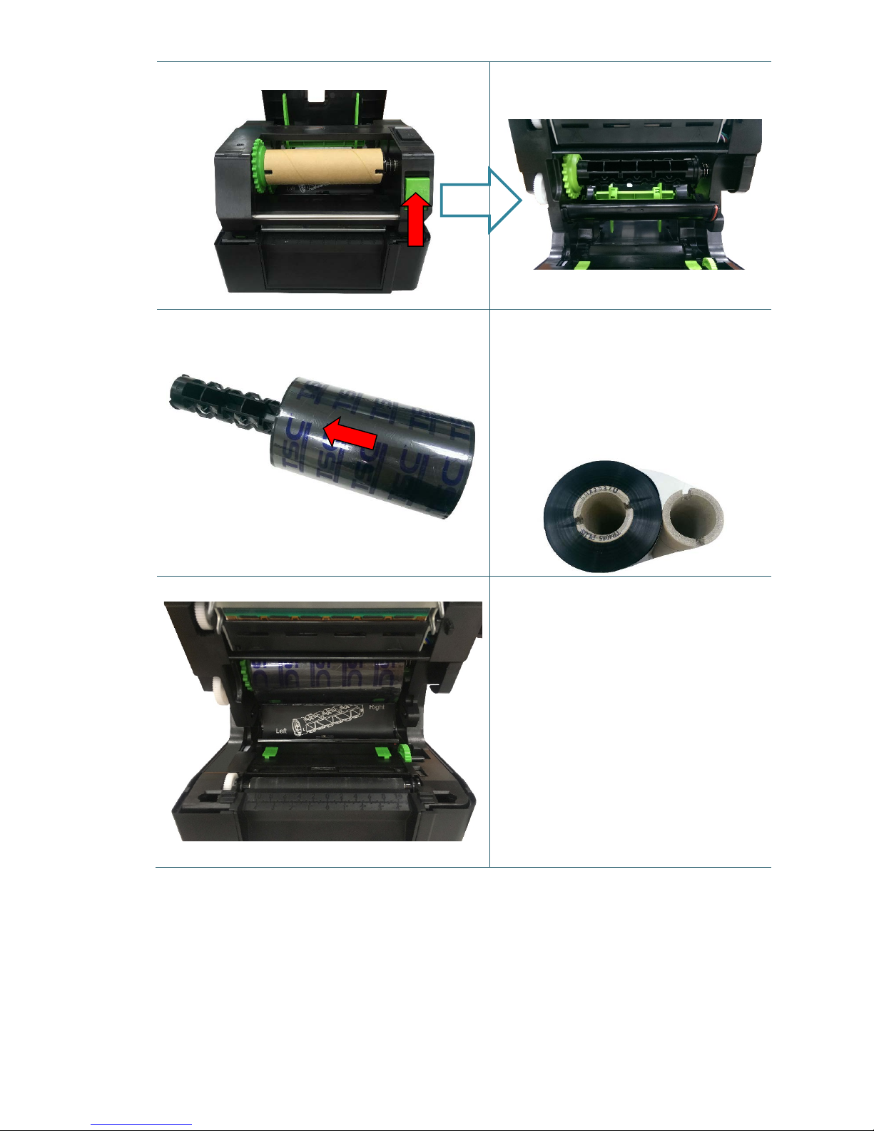
4. Push the print head release button to
open the print head mechanism.
5. Insert the ribbon to the ribbon
spindle.
Note: The ribbon spindle can be
substituted by insert the ribbon
with notches on both sides to the
ribbon mechanism directly.
6. Insert the right side of ribbon supply
spindle to the ribbon supply hub first.
Then, insert the left side of ribbon
supply spindle to the hole at the left
side of ribbon mechanism.
OPEN
Page 19
13
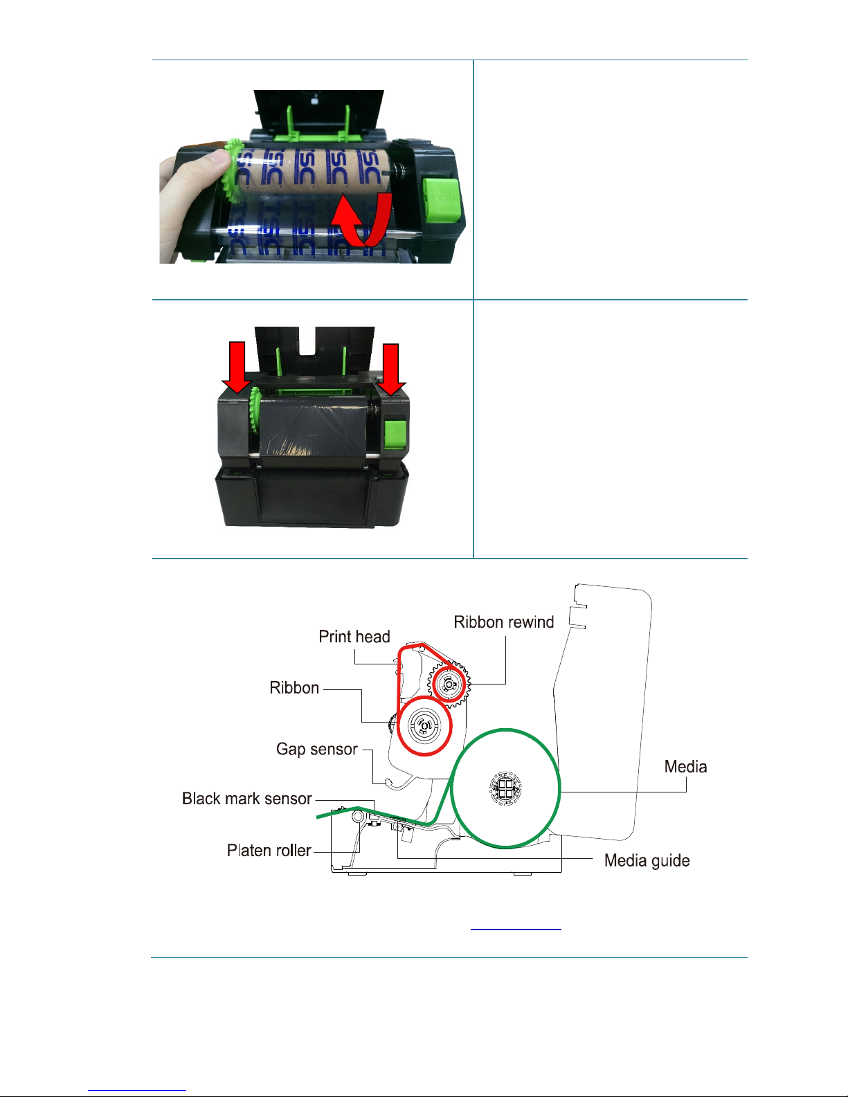
7. Pull the leader of the ribbon through
the print head and stick the leader of
the ribbon onto the ribbon rewind
paper core.
8. Turn the ribbon rewind hub until the
ribbon plastic leader is thoroughly
wound and the black section of the
ribbon covers the print head.
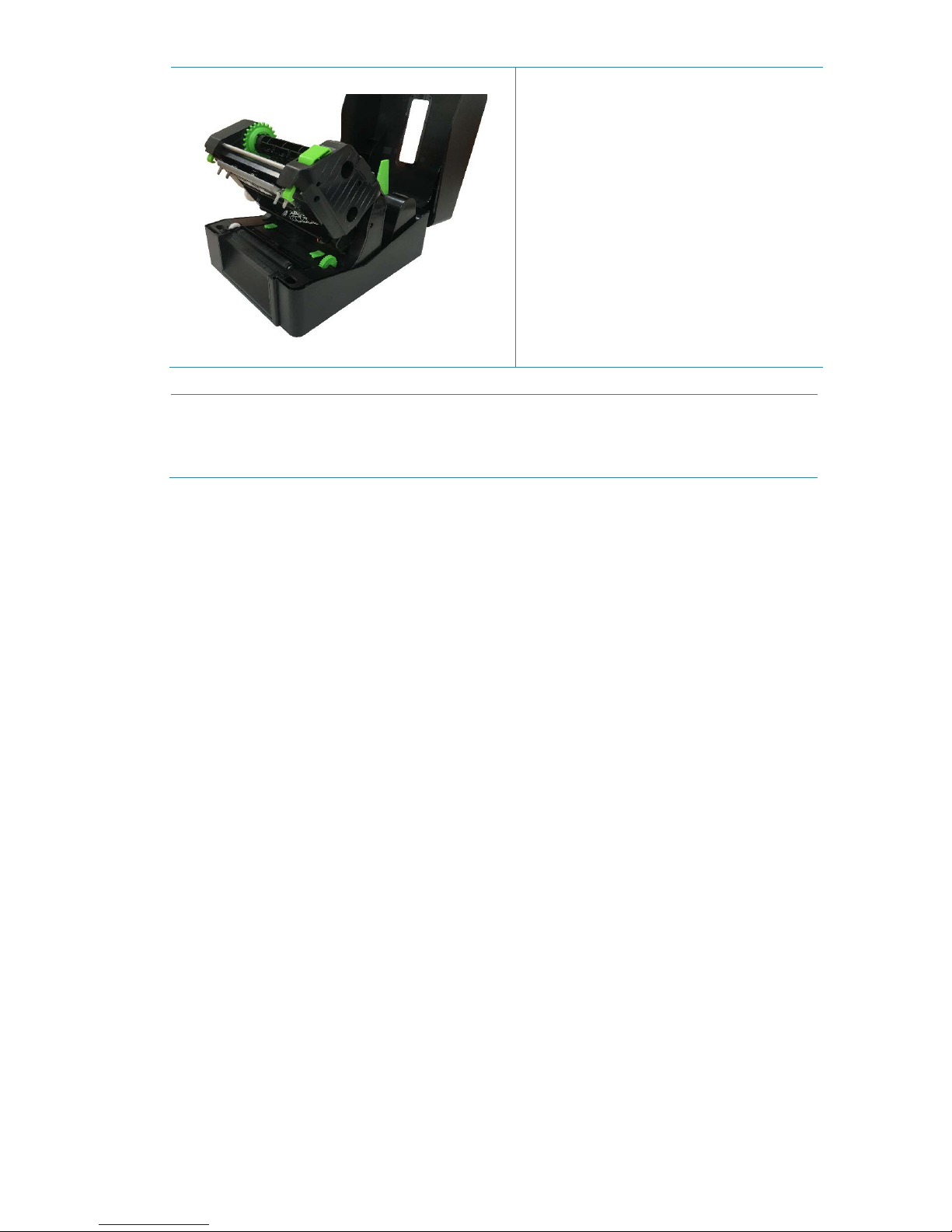
9. Close the print head mechanism with
both hands and make sure the
latches are engaged securely.
Ribbon loading path
Note:
Please refer to printer installation videos at TSC YouTube.
Page 20
14
3.3 Loading the Media
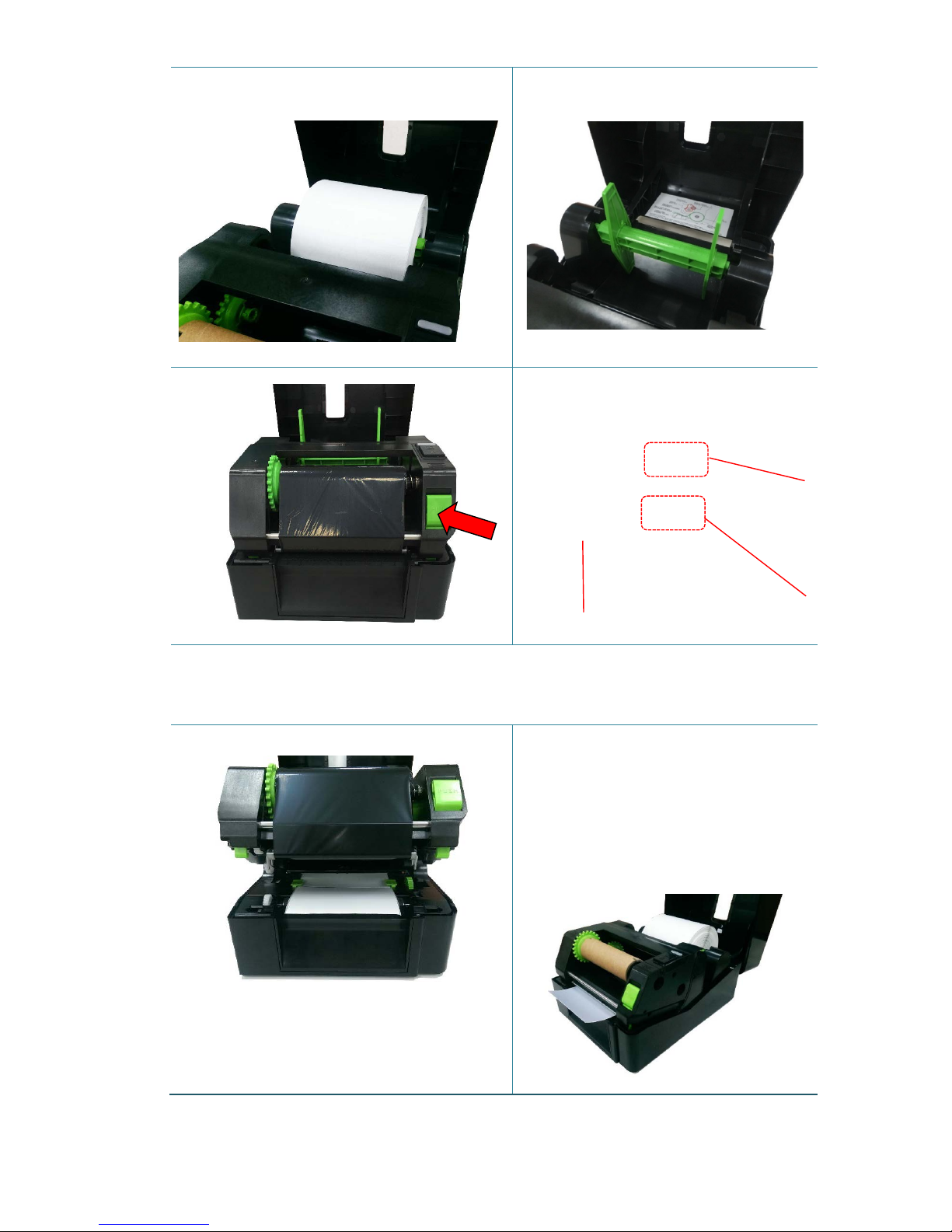
3.3.1 Loading the Roll Labels
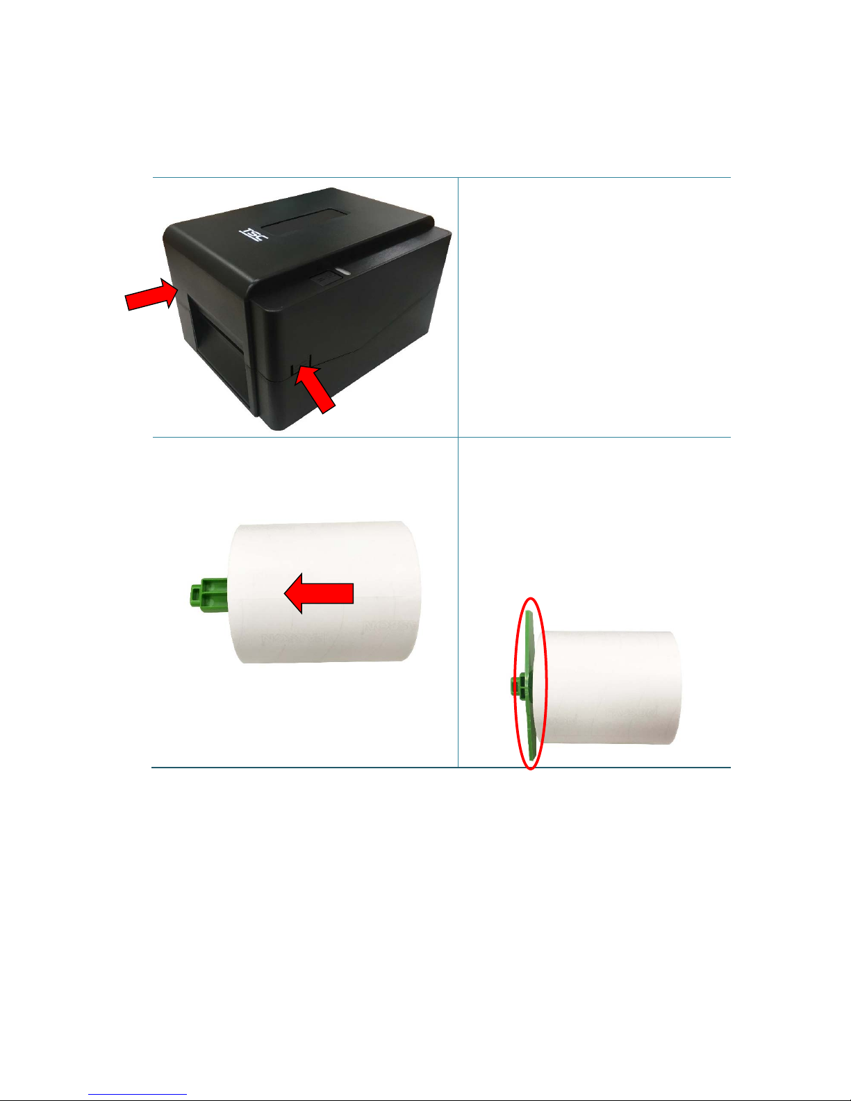
1. Open the printer top cover by
pressing the top cover open tabs
located on each side of the printer.
2. Insert the paper roll into the media
supply spindle and use two fixing
tabs to fix the paper roll onto the
center of the spindle. (If your paper
width is 4”, you can remove th e 1.5”
adapters on both side of the media
supply spindle.)
Page 21
15
3. Place the paper roll onto the paper
roll mount.
4. Push the print head release button
to open the print head mechanism.
Note: The black mark sensor position is moveable and the gap sensor is fixed.
Please make sure the gap or black mark is at the location where media gap/black
mark will pass through for sensing.
5. Feed the paper, printing side face
up, through the media bar, media
sensor and place the label leading
edge onto the platen roller. Move
the media guides to fit the label
width.
Platen roller
Black mark
sensor/ Gap
sensor
(emitter)
Gap sensor
(transmitter)
Media spindle with two 1.5” adapters
Page 22
16
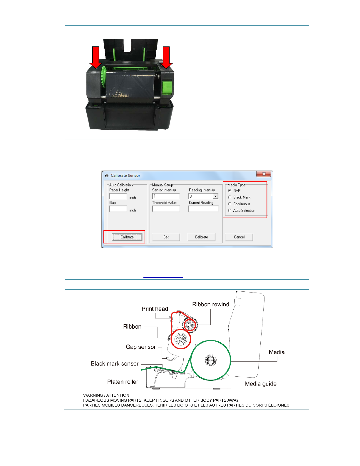
6. Close the print head mechanism
with both hands and make su re the
latches are engag ed securely.
7. Use “Diagnostic Tool” to set the media sensor type and calibrate the selected
sensor. (Start the “Diagnostic tool” Select the “Printer Configuration” tab Click
the “Calibrate Sensor” button ) Please refer to section 5.3.
Note:
* Please calibrate the gap/ black mark sensor when changing media.
* Please refer to videos at TSC YouTube.
Media Loading path
1
2
Page 23
17
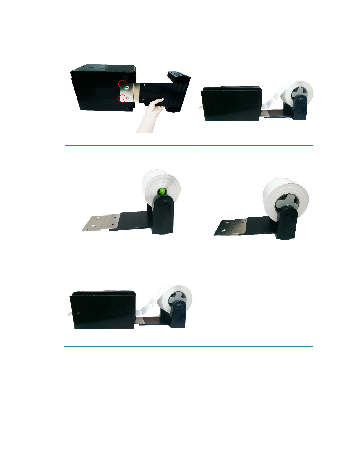
3.3.2 External Label Roll Mount Installation (Option)
1. Attach the extended plate on the
bottom of the printer.
2. Insert a 3” (or 1”) label spindle into a
paper roll. Then, install it on the
external paper roll mount.
3. Feed the media through the rear
external label entrance chute.
1” label spindle
3” label spindle
Page 24
18
4. Refer to chapter 3.3.1 to install the
label. Use “Diagnostic Tool” to set
the media sensor type and calibrate
the selected sensor.
Note:
Please calibrate the gap/black mark sensor when changing media.
4. LED and Button Functions
This printer has one button and one three-color LED indicator. By indicating the LED with
different color and pressing the button, printer can feed labels, pause the printing job, select
and calibrate the media sensor, print printer self-test report, reset printer to defaults
(initialization). Please refer to the button operation below for different functions.
Page 25

19
4.1 LED Indicator
LED Color Description
Green/Solid
This illuminates that the power is on and the device is ready to
use.
Green/Flash This illuminates that the system
is downloading data from PC to
memory or the printer is paused.
Amber This illuminates that the system is clearing data from printer.
Red/Solid This illuminates printer head open, cutter error.
Red/Flash
This illuminates a printing error, such as head open, paper
empty, paper jam, ribbon empty, or memory error etc.
4.2 Regular Button Functions
1. Feed labels
When the printer is at ready states (Green/Solid), pr ess the button to feed one label to the
beginning of next.
2. Pause the printing job
When the printer is at printing states, press the button to pause a print job. When the printer is
paused the LED will be green blinking. Press the button again to continue the printing job.
4.3 Power-on Utilities
There are six power-on utilities to set up and test printer hardware. These utilities are activated
by pressing FEED button then turning on the printer power simultaneously and release the
button at different color of LED.
Please follow the steps below for different power-on utilities.
1. Turn off the printer power switch.
2. Hold on the button then turn on the power switch.
3. Release the button when LED indicates with different color for different functions.
Page 26

20
Power on utilities The LED color will be changed as following pattern:
LED color
Functions
Amber Red
(5 blinks)
Amber
(5 blinks)
Green
(5 blinks)
Green/Amber
(5 blinks)
Red/Amber
(5 blinks)
Solid green
1. Gap / black mark sensor calibration
Release
2. Gap / black mark sensor calibration,
Self-test and enter dump mode
Release
3. Printer initialization
Release
4. Set black mark sensor as media
sensor and calibrate the black mark
sensor
Release
5. Set gap sensor
as media sensor and
calibrate the gap sensor
Release
6. Skip AUTO.BAS
Release
4.3.1 Gap/Black Mark Sensor Calibration
Gap/black mark sensor sensitivity should be calibrated at the following conditions:
1. A brand new printer
2. Change label stock
3. Printer initialization
Please follow the steps below to calibrate the ribbon and gap/black mark sensor.
1. Turn off the power switch.
2. Hold on the button then turn on the power switch.
3. Release the button when LED becomes red and blinking. (Any red will do during the 5 bli nks).
It will calibrate the ribbon sensor and gap/black mark sensor sensitivity.
The LED color will be changed as following order:
Amber red (5 blinks) amber (5 blinks) green (5 blinks) green/amber (5 blinks)
red/amber (5 blinks) solid green
Note:
Please select gap or black mark sensor by sending GAP or BLINE command to printer prior to
calibrate the sensor.
For more information about GAP and BLINE command, please refer to TSPL/TSPL2 programming
manual.
Page 27

21
4.3.2 Gap/Black Mark Calibration, Self-test and Dump Mode
While calibrate the gap/black mark sensor, printer will measure the label length, print the
internal configuration (self-test) on label and then enter the dump mode. To calibrate gap or
black mark sensor, depends on the sensor setting in the last print job.
Please follow the steps below to calibrate the sensor.
1. Turn off the power switch.
2. Hold on the button then turn on the power switch.
3. Release the button when LED becomes amber and blinking. (Any amber will do during the 5
blinks)
The LED color will be changed as following order.
Amber red (5 blinks) amber (5 blinks) green (5 blinks) green/amber (5 blinks)
red/amber (5 blinks) solid green
4. It calibrates the sensor and measures the label length and prints internal settings then enter
the dump mode.
Note:
Please select gap or black mark sensor by Diagnostic Tool or by GAP or BLINE command prior to
calibrate the sensor.
For more information about GAP and BLINE command, please refer to TSPL/TSPL2 programming
manual.
Page 28
22
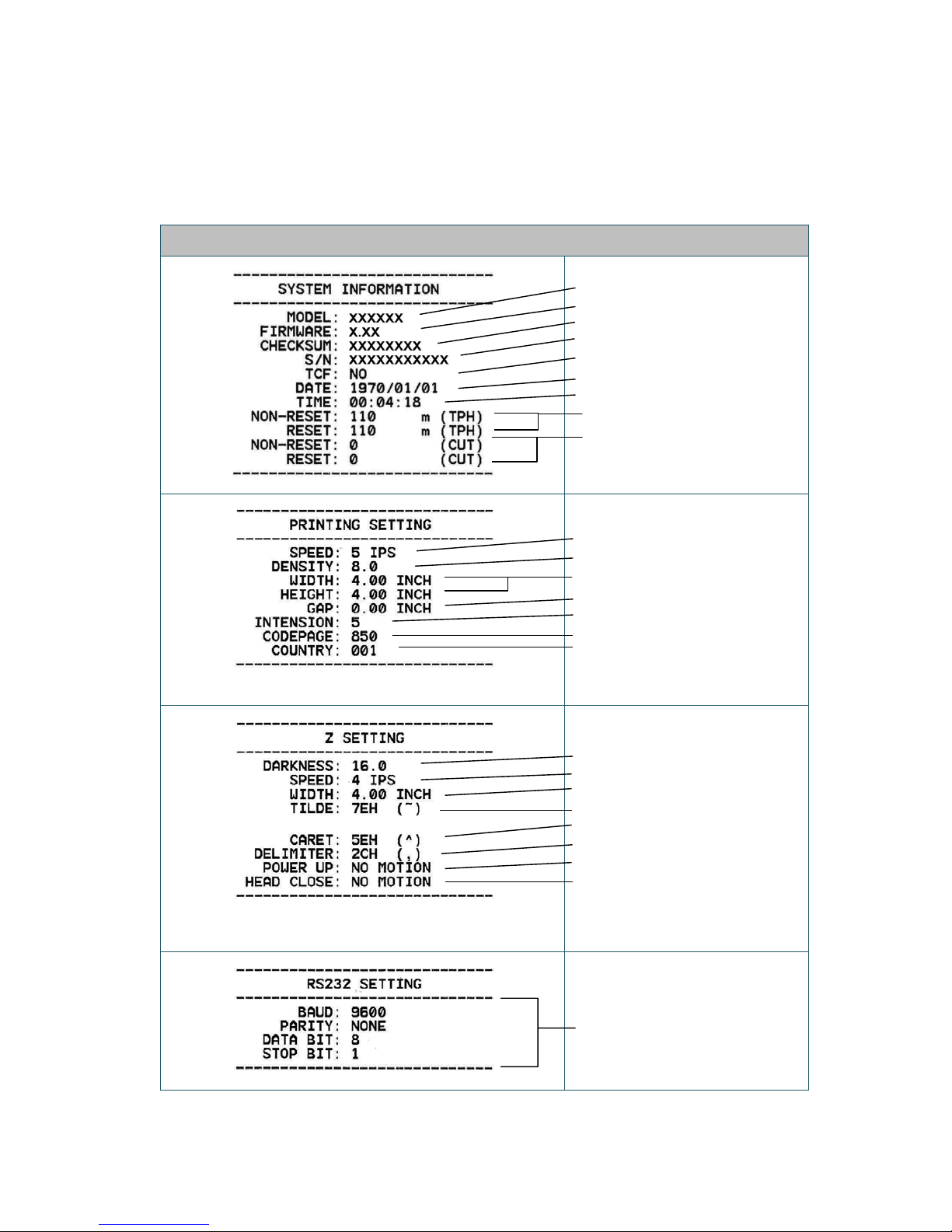
Self-test
Printer will print the printer configuration after gap/black mark sensor calibration. Self-test
printout can be used to check if there is any dot damage on the heater element, printer
configurations and available memory space.
Self-test printout
Model name
F/W version
Firmware checksum
Printer S/N
TSC configuration file
System date
System time
Printed mileage (meter)
Cutting counter
Print speed (inch/sec)
Print darkness
Label size (inch)
Gap distance (inch)
Gap/black mark sensor intension
Code page
Country code
ZPL setting information
Print darkness
Print speed (inch/sec)
Label size
Control prefix
Format prefix
Delimiter prefix
Printer power up motion
Printer head close motion
Note:
ZPL is emulating for Zebra
®
language.
RS232 serial port
configuration
Page 29
23
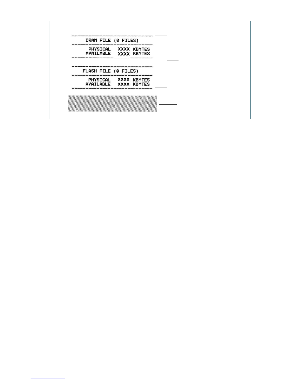
Numbers of download files
Total & available memory
space
Print head check pattern
Page 30

24
Dump mode
Printer will enter dump mode after printing printer configuration. In the dump mode, all
characters will be printed in 2 columns as following. The left side characters are received from
your system and right side data are the corresponding hexadecimal value of the characters. It
allows users or engineers to verify and debug the program.
Note:
1. Dump mode requires 4” wide paper width.
2. Turn off / on the power to resume printer for normal printing.
4.3.3 Printer Initialization
Printer initialization is used to clear DRAM and restore printer settings to defaults.
Printer initialization is activated by the following procedures.
1. Turn off the power switch.
2. Hold on the button then turn on the power switch.
3. Release the button when LED turns green after 5 amber blinks. (Any green will do during the
5 blinks).
The LED color will be changed as following:
Amber red (5 blinks) amber (5 blinks) green (5 blinks) green/amber (5 blinks)
red/amber (5 blinks) solid green
ASCII Data
Hex decimal data related to left
column of ASCII data
Page 31

25
Printer configuration will be restored to defaults as below after initialization.
Parameter Default setti ng
Speed 127 mm/sec (5 ips) (203DPI)
76 mm/sec (3 ips) (300DPI)
Density 8
Label Width
4" (101.5 mm)
Label Height
4" (101.5 mm)
Sensor Type Gap sensor
Gap Setting
0.12" (3.0 mm)
Print Direction 0
Reference Point 0,0 (upper left corner)
Offset 0
Tear Mode On
Peel off Mode Off
Cutter Mode Off
Code Page 850
Country Code 001
Clear Flash Memory No
4.3.4 Set Black Mark Sensor as Media Sensor and Calibrate the Black Mark Sensor
Please follow the steps as below.
1. Turn off the power switch.
2. Hold on the button then turn on the power switch.
3. Release the button when LED turns green/amber after 5 green blinks. (Any green/amber will
do during the 5 blinks).
The LED color will be changed as following:
Amber red (5 blinks) amber (5 blinks) green (5 blinks) green/amber (5 blinks)
red/amber (5 blinks) solid green
4.3.5 Set Gap Sensor as Media Sensor and Calibrate the Gap Sensor
Please follow the steps as below.
1. Turn off the power switch.
2. Hold on the button then turn on the power switch.
3. Release the button when LED turns red/amber after 5 green/amber blinks. (Any red/amber
will do during the 5 blinks).
The LED color will be changed as following:
Page 32

26
Amber red (5 blinks) amber (5 blinks) green (5 blinks) green/amber (5 blinks)
red/amber (5 blinks) solid green
4.3.6 Skip AUTO.BAS
TSPL2 programming language allows user to download an auto execution file to flash memory.
Printer will run the AUTO.BAS program immediately when turning on printer power. The
AUTO.BAS program can be interrupted without running the program by the power-on utility.
Please follow the procedures below to skip an AUTO.BAS program.
1. Turn off printer power.
2. Press the FEED button and then turn on power.
3. Release the FEED button when LED becomes solid green.
The LED color will be changed as following:
Amber red (5 blinks) amber (5 blinks) green (5 blinks) green/amber (5 blinks)
red/amber (5 blinks) solid green
4. Printer will be interrupted to run the AUTO.BAS program.
Page 33
27
5. Diagnostic Tool
TSC’s Diagnostic Utility is an integrated tool incorporating features that enable you to explore
a printer’s settings/status; change a printer’s settings; download graphics, fonts and firmware;
create a printer bitmap font; and send additional commands to a printer. With the aid of this
powerful tool, you can review printer status and settings in an instant, which makes it much
easier to troubleshoot problems and other issues.
5.1 Start the Diagnostic To ol
1. Double click on the Diagnostic tool icon to start the software.
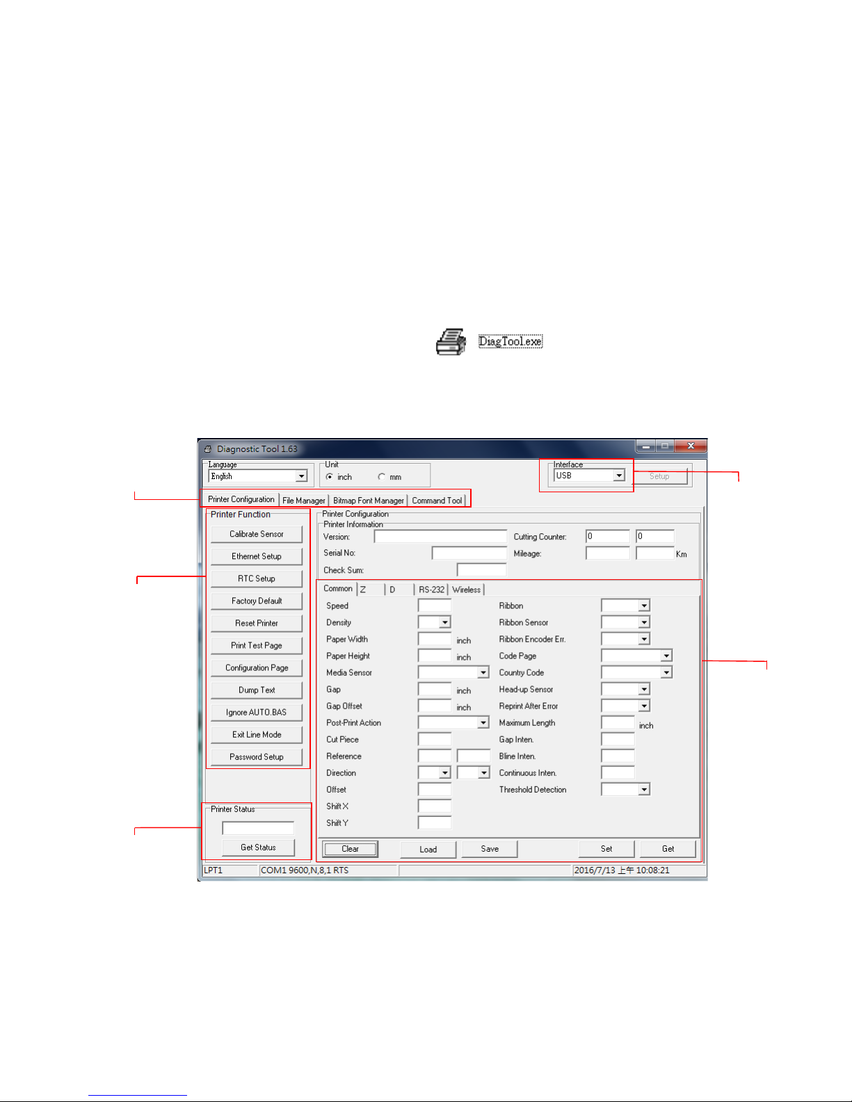
2. There are four features (Printer Configuration, File Manager, Bitmap Font Manager,
Command Tool) included in the Diagnostic utility.
Features tab
Printer functions
Interface
Printer Status
Printer setup
Page 34
28
5.2 Printer Function
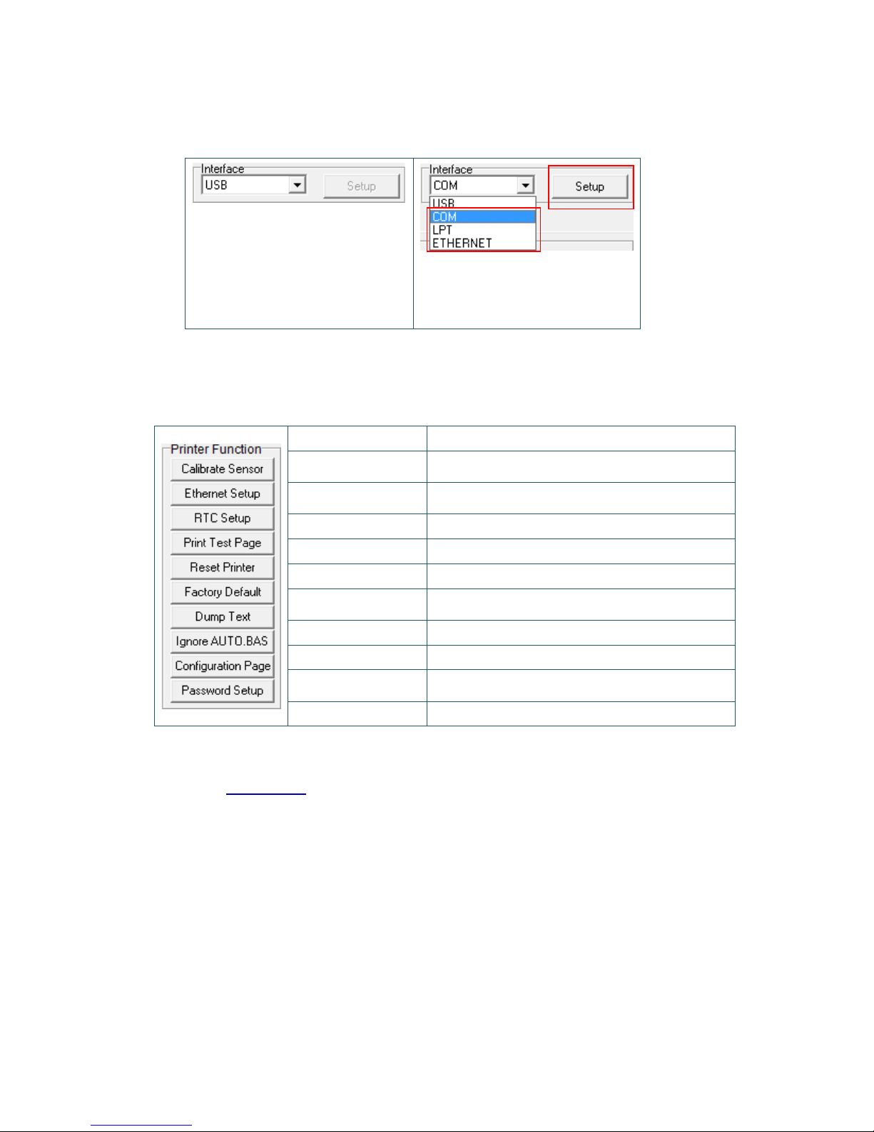
1. Select the PC interface connected with bar code printer.
The default interface setting is
USB interface. If USB interface
is connected with printer, no
other settings need to be
changed in the interface field.
2. Click the “Printer Function” button to setu p.
3. The detail functions in the Printer Function Group are listed as below.
Function Description
Calibrate Sensor
Calibrate the sensor specified in the Printer Setup
group media sensor field
Ethernet Setup
Setup the IP address, subnet mask, gateway for
the on board Ethernet
RTC Setup Synchronize printer Real Time Clock with PC
Print Test Page Print a test page
Reset Printer Reboot printer
Factory Default
Initialize the printer and restore the settings to
factory default. (Please refer section 4.3.3)
Dump Text To activate the printer dump mode.
Ignore AUTO.BAS Ignore the downloaded AUTO.BAS program
Configuration Page
Print printer configuration (Please refer section
4.3.2)
Password Setup Set the password to protect the settings
For more information about Diagnostic Tool, please refer to the diagnostic utility quick start
guide on TSC website.
1 2
Page 35
29
5.3 Calibrating Media Sensor by Diagnostic Tool
5.3.1 Auto Calibration
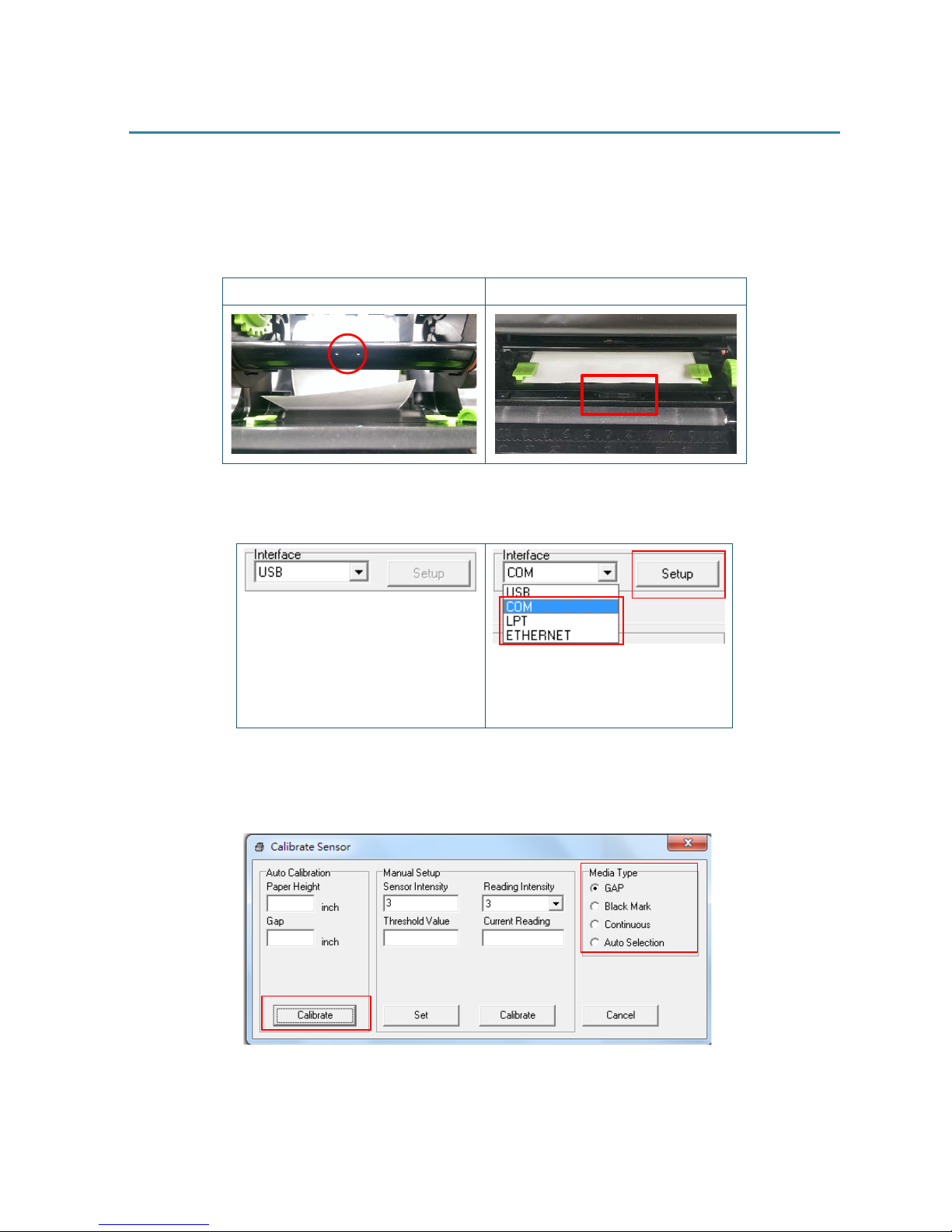
1. Make sure the media is already installed and print head mechanism is closed. (Please refer
to section 3.3.)
Gap sensor Black mark sensor
2. Turn on the printer power switch.
3. Open Diagnostic tool and set interface. (The default setting is USB.)
The default interface setting is
USB interface. If USB interface
is connected with printer, no
other settings need to be
changed in the interface field.
4. Click the “Calibrate Sensor” button.
5. Select the media type and click the “Calibrate” button.
1
2
1
2
Page 36

30
6. Troubleshooting
6.1 Common Problems
The following guide lists the most common problems that may be encountered when operating
this bar code printer. If the printer still does not function after all suggested solutions have been
invoked, please contact the Customer Service Department of your purchased reseller or
distributor for assistance.
Problem Possible Cause Recovery Procedure
Power indicator does not
illuminate.
* The power cord is not
properly connected.
* Plug the power cord in printer and outlet.
* Switch the printer on.
- The printer status from
DiagTool shows “Head
Open”.
- The LED shows “Red
(blinking)”.
* The printer carriage is open. * Please close the print carriage.
- The printer status from
DiagTool shows “
Ribbon End
Err.” Or “Ribbon Encoder
Err.”
- The LED shows “Red
(blinking)”.
* Running out of ribbon.
* The ribbon is installed
incorrectly.
* Supply a new ribbon roll.
* Please refer to the steps on section 3.2 to
re-install the ribbon.
- The printer status from
DiagTool shows “Out of
Paper”.
- The LED shows “Red
(blinking)”.
* Running out of label.
* The label is installed
incorrectly.
* Gap/black mark sensor is not
calibrated.
* Supply a new label roll.
* Please refer to the steps on section 3.3 to
reinstall the label roll.
* Calibrate the gap/black mark sensor.
- The printer status from
DiagTool shows “Paper Jam”.
- The LED shows “Red
(blinking)”.
* Gap/black mark sensor is not
set properly.
* Make sure label size is set
properly.
* Labels may be stuck inside
the printer mechanism.
* Calibrate the gap/black mark sensor.
* Set label size correctly.
Not Printing
* Cable is not
well connected to
serial or USB interface or
parallel port.
* The serial port cable pin
configuration is not pin to pin
connected.
* Re-connect cable to interface.
* Chang a new cable.
* Ribbon and media are not compatible.
* Verify the ribbon-inked side.
* Reload the ribbon again.
* Clean the print head.
* The print density setting is incorrect.
* Print head’s harness connector is not well
connected with printheat. Turn off the
printer and plug the connector again.
* Check
your program if there is a command
PRINT at the end o
f the file and there must
have CRLF at the end of each command
Page 37
31
line.
Memory full
( FLASH / DRAM )
* The space of FLASH/DRAM
is full.
* Delete unused files in the FLASH/DRAM.
Poor Print Quality
* Ribbon and media is loaded
incorrectly
* Dust or adhesive
accumulation on the print
head.
* Print density is not set
properly.
* Printhead element is
damaged.
* Ribbon and media are
incompatible.
* The printhead pressure
is not
set properly.
* Reload the supply.
* Clean the print head.
* Clean the platen roller.
* Adjust the print density and print speed.
* Run printer self-test and check the print
head test pattern if there is dot missing in
the pattern.
* Change proper ribbon or proper label
media.
* The print head mechanism does not latch
the print head properly.
Skip labels when printing
* Label size is not specified
properly.
* Sensor sensitivity is not set
properly.
* The media sensor is covered
with dust.
* Check if label size is setup correctly.
* Calibrate the sensor by Auto Gap or
Manual Gap options.
* Clear the GAP/Black mark sensor by
blower.
The printing position of small
label is incorrect
*
Media sensor sensitivity is not
set properly.
* Label size is incorrect.
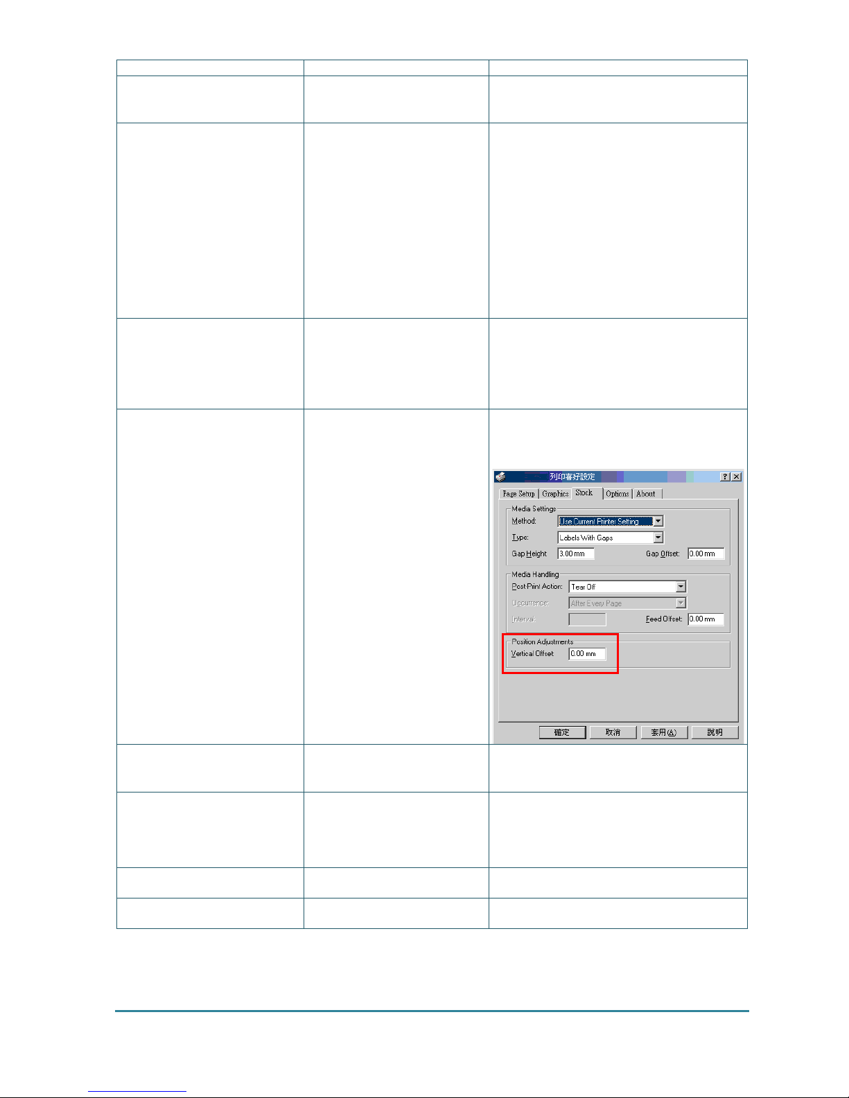
* The vertical offset setting in
the driver is incorrect.
* Calibrate the sensor sensitivity again.
* Set the correct label size and gap size.
*
If using the software BarTender, please set
the vertical offset in the driver.
Missing printing on
the left or
right side of label
* Wrong label size setup. * Set the correct label size.
Wrinkle problem
* Ribbon installation is
incorrect.
* Media installation is incorrect.
* Print density is incorrect.
* Media feeding is incorrect.
* Please set the suitable density to have
good print quality.
*
Make sure the label guid e touch the edge
of the media guide.
Gray line on the blank label
* The print head is dirty.
* The platen roller is dirty.
* Clean the print head.
* Clean the platen roller.
Irregular printing
* The printer is in Hex Dump
mode.
* Turn off and on the printer to skip the
dump mode.
7. Maintenance
Page 38
32
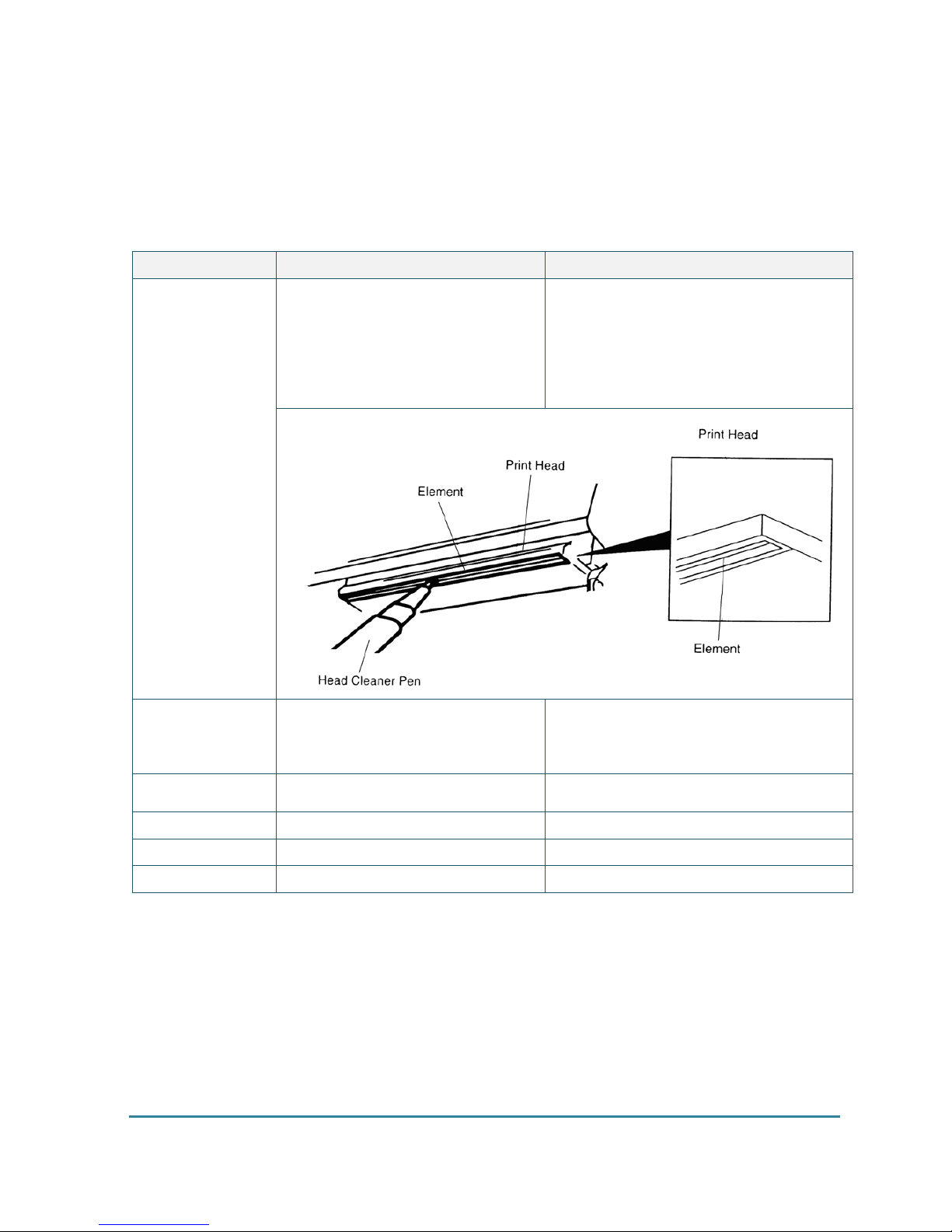
This session presents the clean tools and methods to maintain your printer.
1. Please use one of following material to clean the printer.
Cotton swab
Lint-free cloth
Vacuum / Blower brush
100% ethanol
2. The cleaning process is described as following,
Printer Part Method Interval
Print Head
1. Always turn off the printer before
cleaning the print head.
2. Allow the print head to cool for a
minimum of one minute.
3. Use a cotton swab and 100%
ethanol to clean the print head
surface.
Clean the print head when changing a new
label roll.
Platen Roller
1. Turn the power off.
2. Rotate the platen roller and wipe
it
thoroughly with 100% ethanol and
a cotton swab, or lint-free cloth.
Clean the platen roller when changing a
new label roll.
Tear Bar/Peel Bar
Use the lint-free cloth with 100%
ethanol to wipe it.
As needed
Sensor
Compressed air or vacuum Monthly
Exterior
Wipe i t with water-dampened cloth
As needed
Interior
Brush or vacuum As needed
Note:
Do not touch printer head by hand. If you touch it careless, please use ethanol to clean it.
Please use 100% Ethenol. DO NOT use medical alcohol, which may damage the printer head.
Regularly clean the print head and supply sensors once change a new ribbon to keep printer
performance and extend printer life.
Revise History
Page 39

33
Date Content Editor
Page 40

34
Corporate Headquarters Li Ze Plant
9F., No.95, Minquan Rd., Xindian Dist., No.35, Sec. 2, Ligong 1st Rd., Wujie Township,
New Taipei City 23141, Tai wan (R.O.C.) Yilan County 26841, Taiwan (R.O.C.)
TEL: +886-2-2218-6789 TEL: +886-3-990-6677
FAX: +886-2-2218-5678 FAX: +886-3-990-5577
Web site: www .tscp r inters.com
E-mail: [email protected]
TSC Auto ID Technology Co., Ltd.
 Loading...