

Page 1
Quick Installation Guide
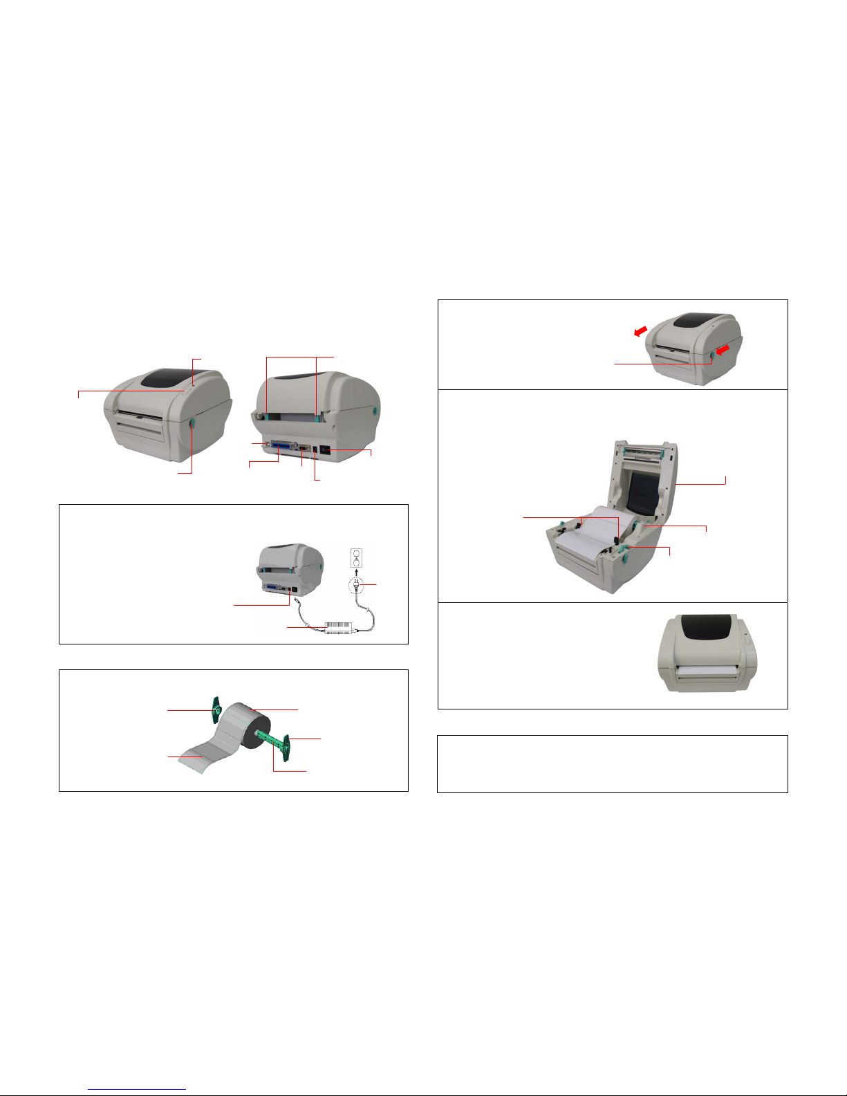
Printer overview
Printer Installation
1. Arrange this printer on a reliable flat surface and make sure the power switch is off.
2. Connect the printer to a computer mainframe with a provided Centronics, RS-232C or USB cable.
3. Plug the power cord into the power jack
connector at the rear of the printer, then plug
the power cord into a properly grounded outlet.
Loading the Label
1. Insert a 1” label spindle into a paper roll ( * If your paper core is 1 inch, remove the 1.5” core adapter from
the fixed tab).
2. Open the printer top cover by pushing
forward the top cover open levers.
3. Orient a roll of paper on the paper roll mount.
4. Feed the paper, printing side face up, through the label guide and pass over the platen.
5. Adjust the black center-biased label guides in or out turning adjustment knob so they are slightly touch the
edges of the label backing.
6. Close the printer top cover slowly and make sure the
cover locks latch securely.
7. Use the “Diagnostic tool” to set the media sensor
type and calibrate the selected sensor. (See
“Diagnostic Tool” and “Sensor Calibrate” in the next
page)
Note:
1. Please calibrate the gap/black mark sensor when
changing media.
2. Failure to securely close and lock the cover will
result in poor print quality.
Button Functions
(1) Feed labels
When the printer is ready, press the button to feed one label to the beginning of next label.
(2) Pause the printing job
When the printer is printing, press the button to pause a print job. When the printer is paused the LED will
blink green. Press the button again to continue the printing job.
Centronics
RS-232
Power Jack
Power Switch
Feed Button
Rear Paper Guide
LED Indicator
Paper Roll Mount
Printer Top Cover
USB
Top Cover Open Lever
Page 1 of 2
Power Supply
Power Jack
Plug
Paper Roll
1” label spindle
Printing Side
Face Up
1.5” Core
Adapter*
Fixed Tab
Top Cover Open Lever
Label Guide
Adjustment Knob
Page 2
Diagnostic Tool
The Diagnostic Utility is a toolbox that allows users to explore the printer's settings and status; change printer
settings; download graphics, fonts, and firmware; create printer bitmap fonts; and to send additional
commands to the printer. Using this convenient tool, you can explore the printer status and settings and
troubleshoot the printer.
Note: This utility works with printer firmware V6.00 and later versions.
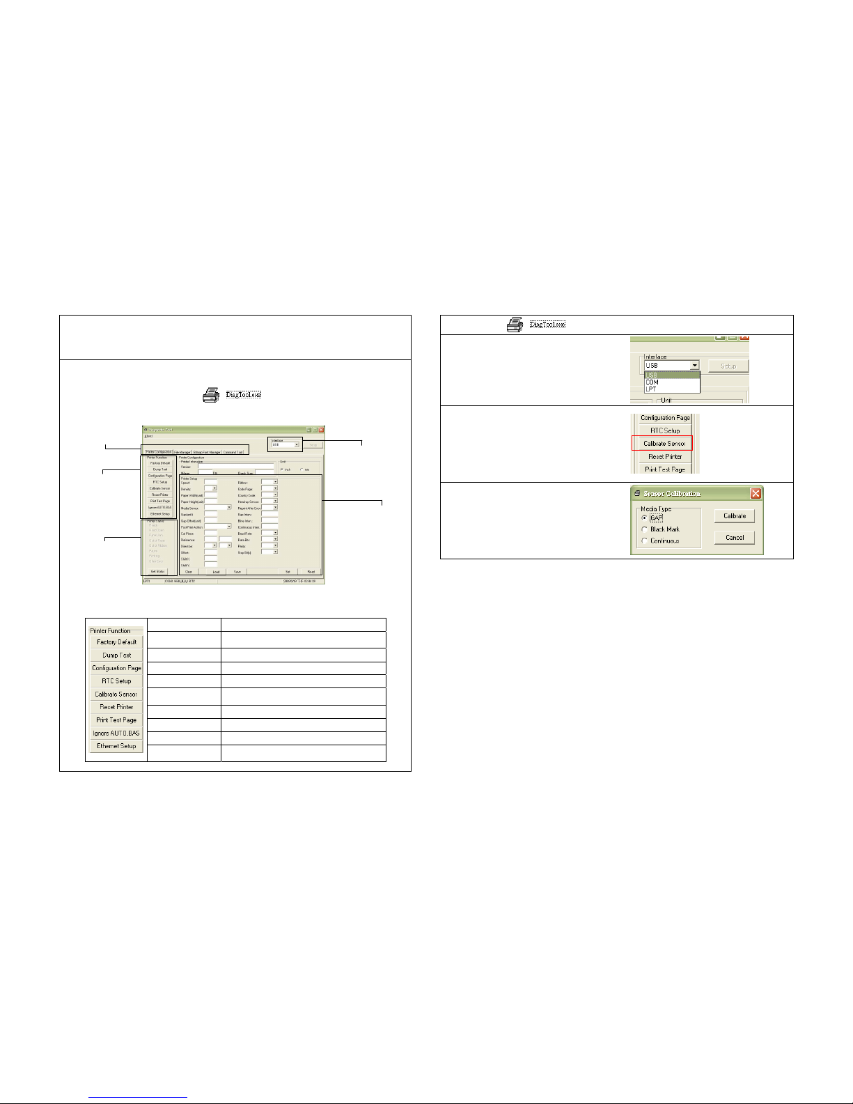
Start the Diagnostic Tool:
(1) Double click on the Diagnostic tool icon
to start the software.
(2) There are four features (Printer Configuration, File Manager, Bitmap Font Manager, Command Tool)
included in the Diagnostic utility.
(3) The detail functions in the Printer Function Group are listed as below.
Function Description
Factory Default
Initialize the printer and restore the settings to
factory default.
Dump Text To activate the printer dump mode.
Configuration Page Print printer configuration.
RTC Setup Synchronize printer Real Time Clock with PC.
Calibrate Sensor
Calibrate the sensor specified in the Printer Setup
group media sensor field.
Reset Printer Reboot the printer.
Print Test Page Print a test page.
Ignore AUTO.BAS Ignore the downloaded AUTO.BAS program.
Ethernet Setup
Setup the IP address, subnet mask, gateway for
the on board Ethernet.
Sensor Calibrate
1. Double click the icon to start the “Diagnostic tool” software.
2. Select the PC interface connected with bar code
printer.
3. Click the “Calibrate Sensor” button to setting.
4. Select the media type then click the “Calibrate” button.
* For more information and features about this printer, please refer to the User’s Manual inside the CD disk.
Features tab
Printer functions
Interface
Printer Status
Printer setup
Page 2 of 2
P/N:39-0000113-20LF
 Loading...