

TSC Alpha-4L Service Manual

i
SERVICE
MANUAL
Alpha-4L
Direct Thermal Portable Printer

ii
Contents
1.
FUNDAMENTAL OF THE SYSTEM ................................ 2
1.1 Overview........................................................................................................... 2
2. ELECTRONICS ............................................... 4
2.1 Summary of Board Connectors ...................................................................... 4
3. MECHANISM ............................................... 12
3.1 Replacing the Platen Roller ........................................................................... 12
3.2 Replacing the Print Head Assembly ............................................................. 13
3.3 Replacing the Keys Control Board/ LCD Control Board ............................. 17
3.4 Replacing the Peel-off Sensor Module ......................................................... 18
3.5 Replacing the Bluetooth Module .................................................................. 19
3.6 Replacing the Main Board Assembly ........................................................... 20
3.7 Replacing the Stepping Motor ...................................................................... 21
3.8 Replacing the Gap Sensor Assembly ........................................................... 22
3.9 Replacing the Media Holder Assembly ........................................................ 23
3.10 Replacing the Hand Open Sensor Assemble ............................................... 24
3.11 Replacing the Peel-off Module ...................................................................... 25
3.12 Replacing the Black Mark Sensor Assembly ............................................... 26
3.13 Replacing the Charger Board Assembly ...................................................... 27
3.14 Replacing the Wi-Fi Module (Option)............................................................ 28
3.15 Replacing the RTC Battery (Option) ............................................................. 29
4. TROUBLESHOOTING ......................................... 30
4.1 Common Problems ........................................................................................ 30
5. MAINTENANCE ............................................. 32
Revise History ................................................ 33

2
1. FUNDAMENTAL OF THE SYSTEM
1.1 Overview
Front View
1.
Power on/off button
2.
Feed button
3.
Printer status LED indicator
4.
Battery status LED indicator
5.
Media cover release button
6.
Peel-off sensor (Without for linerless model)
7.
Print head
8.
Transmissive sensor – Gap sensor
9.
Media holder lock switch
10.
Media holder
11.
Media cover
12.
Ref lective sensor – Black mark sensor
13.
Platen roller
14.
T ear/Peeler bar (Without for linerless model)
15.
Peeler module
Note:
* The media sensor position is selectable by factory adjustment. Please refer to this figure for
default settings. (Default – center position, black mark in back side)
9 2 1
3
4
6
8
7
5
10
11
12
13
15
14

3
Rear View
1.
Li-ion battery
2.
Belt chip
3.
Battery open clasp
4.
Hanger for shoulder strap
5.
External label entrance chute
6.
USB interface
7.
* MicroSD card socket
8.
Power jack
Note:
* Recommended MicroSD card specification.
SD card spec
SD card
capacity
Approved SD card manufacturer
V1.0, V1.1 MicroSD 128 MB Transcend, Panasonic
V1.0, V1.1 MicroSD 256 MB Transcend, Panasonic
V1.0, V1.1 MicroSD 512 MB Transcend, Panasonic
V1.0, V1.1 MicroSD 1 GB Transcend, Panasonic
V2.0 SDHC CLASS
6
MicroSD 4 GB Transcend
- The DOS FAT file system is supported for the SD card.
- Folders/files stored in the SD card should be in the 8.3 filename format
1
3
2
4
7
6
5
8
4
2. ELECTRONICS
2.1 Summary of Board Connectors
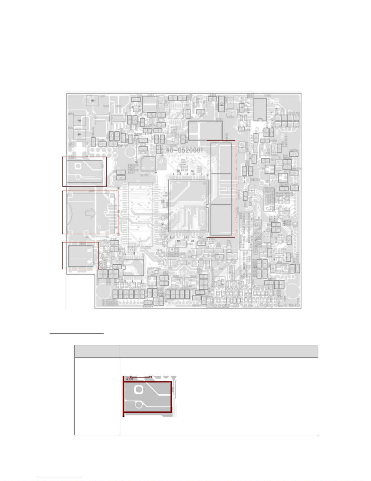
Main board top
Connector Description
J101
DC Jack
12V DC IN
J101
J401
J404
CON101
CON102
CON103

5
J401
Micro SD connector
Pin Description
1 SD_Data2
2 SD_Data3
3 SD_CMD
4 3.3V
5 SD_CLK
6 GND
7 SD_Data0
8 SD_Data1
9 GND
10 GND
J404
Micro USB
Pin Description
1 NC
2 VBUS
3 TX
4 D+
5 RX
6 D7 RTS
8 GND
9 CTS
10 GND
CON101
CON102
CON103
Battery
CON101 pin1~4 & CON102
pin1 for battery positive
CON103 pin1~4 & CON102
pin4 for battery negative
CON102 pin2~3 for NTC
Pin 1
Pin 1
Pin 10
Pin 8
6
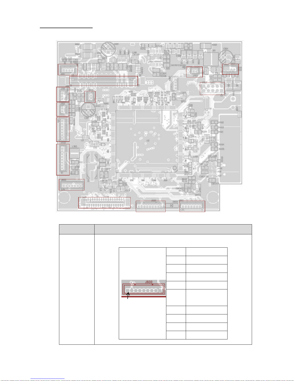
Main board bottom
Connector Description
J600
For LCD & LED board
Pin Description
1 3.3V
2 PEEL_E
3 PEEL_R
4 8V battery
5 LED_Charging
off & low battery
6 LED_Charging
7 Power KEY
8 Feed KEY
9 GND
J600
J601
J602
J603
S1
J402
J702
J701
J501
J403
J703
S101
J301
BAT1
Pin 1
7
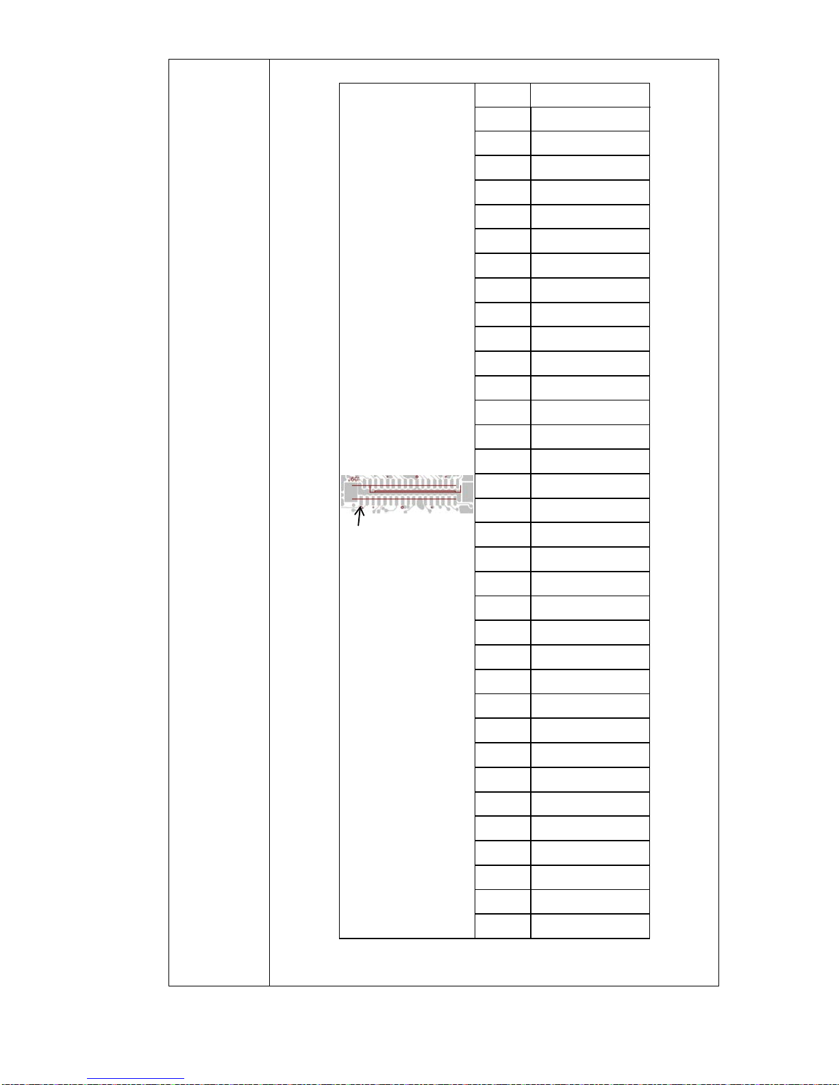
J601
LCD
Pin Description
1 IRS
2 /HPM
3 PS
4 C86
5 NC
6 V0
7 V1
8 V2
9 V3
10 V4
11 NC
12 NC
13 CAP214 CAP2+
15 CAP1+
16 CAP117 CAP3+
18 NC
19 VOUT
20 GND
21 3.3V
22 LCM_D7
23 LCM_D6
24 LCM_D5
25 LCM_D4
26 LCM_D3
27 LCM_D2
28 LCM_D1
29 LCM_D0
30 LCM_RD
31 LCM_WR
32 LCM_A0
33 /LCM_RST
34 /LCM_CS
Pin 1

8
J602
For LED Board
Pin Description
1 3.3V
2 LED_STATUS
3 LED_ERROR
4 LED_FULL
BATTERY
5 LED_HALF
BATTERY
6 LED_BT
7 LED_WIFI
J603
For LCD board
Pin Description
1 A+
2 K3 GND
4 3.3V
5 LED_ERROR
6 MANUAL KEY
7 INFO KEY
S1
Download port
Pin Description
1 3.3V
2 GND
3 /RESET
4 BMS
5 /CS
6 MISO
7 MOSI
8 CLK
J402
WiFi connector
Pin Description
1 3.3V
2 /WIFI_RST
3 WIFI_RXD
4 WIFI_RST
9
5 WIFI_TXD
6 WIFI_CTS
7 GND
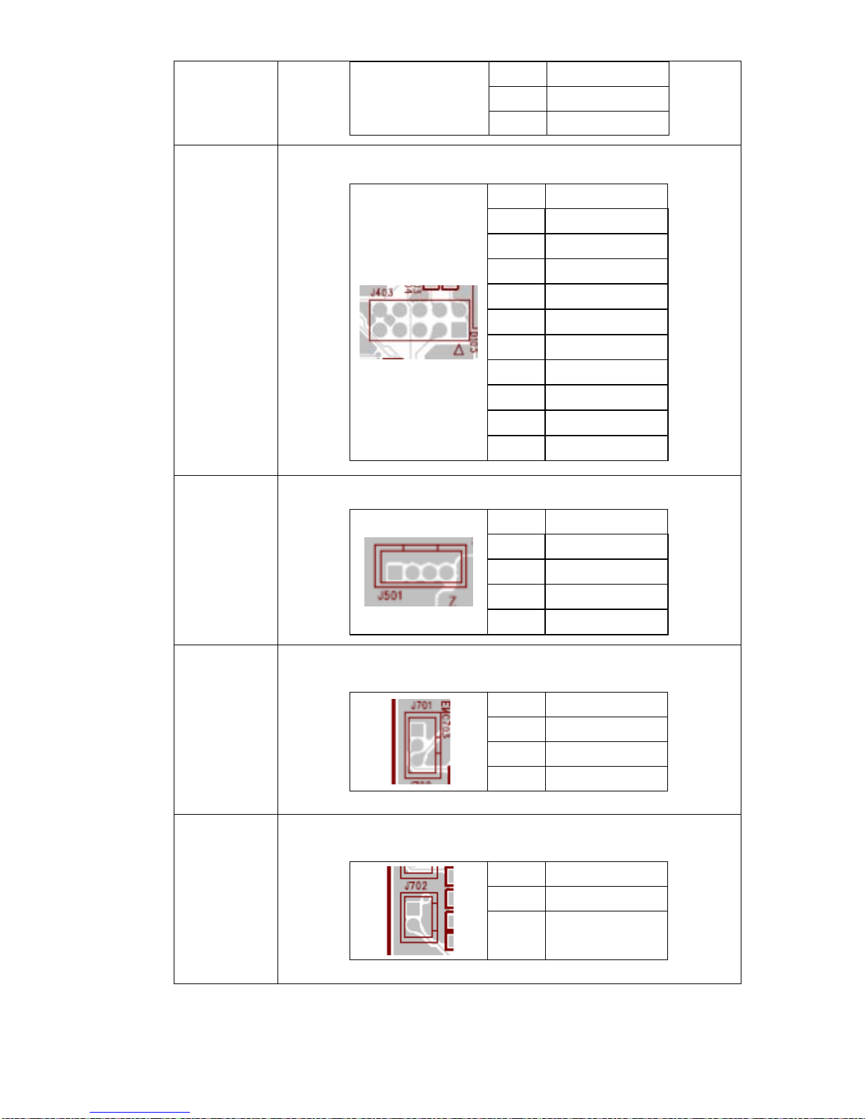
J403
Bluetooth connector
Pin Description
1 3.3V
2 BT_RST
3 BT_RXD
4 BT_RTS
5 BT_TXD
6 BT_CTS
7 BT_DISCON
8 BT_CON
9 NC
10 GND
J501
Stepping motor
Pin Description
1 AOUT1
2 AOUT2
3 BOUT1
4 BOUT2
J701
Black mark sensor
Pin Description
1 3.3V
2 BM_E
3 BM_R
J702
Gap sensor
Pin Description
1 3.3V
2 GAP_R

10
J703
Hand open senor
Pin Description
1 HEAD
2 GND
J301
Print head
Pin Description
1 VH
2 VH
3 VH
4 NC
5 /LAT
6 TPH_CLK
7 3.3V_TPH
8 STB1
9 STB2
10 STB3
11 TM
12 GND
13 GND
14 GND
15 GND
16 GND
17 GND
18 GND
19 GND
20 GND
21 STB4
22 STB5
23 STB6
24 STB7
25 DI
26 VH
27 VH
28 VH
29 GND
30 GND
 Loading...