

Page 1
Limited One Year Warranty
T&S warrants to the original purchaser (other than
for purposes of resale) that such product is free from
defects in material and workmanship for a period of
one (1) year from the date of purchase. During this
one-year warranty period, if the product is found to
be defective, T&S shall, at its options, repair and/
or replace it. To obtain warranty service, products
must be returned to...
T&S Brass and Bronze Works, Inc.
Attn: Warranty Repair Department
2 Saddleback Cove
Travelers Rest, SC 29690
Shipping, freight, insurance, and other transportation charges of the product to T&S and the return
of repaired or replaced product to the purchaser are
the responsibility of the purchaser. Repair and/or
replacement shall be made within a reasonable time
after receipt by T&S of the returned product. This
warranty does not cover Items which have received
secondary finishing or have been altered or modified after purchase, or for defects caused by physical abuse to or misuse of the product, or shipment
of the products.
Any express warranty not provided herein, and
any remedy for Breach of Contract which might arise,
is hereby excluded and disclaimed. Any implied
warranties of merchantability or fitness for a particular purpose are limited to one year in duration. Under
no circumstances shall T&S be liable for loss of
use or any special consequential costs, expenses
or damages.
Some states do not allow limitations on how long
and implied warranty lasts or the exclusion or limitation of incidental or consequential damages, so
the above limitations or exclusions may not apply
to you. Specific rights under this warranty and other
rights vary from state to state.
Installation and
Maintenance
Instructions
WORKBOARD FAUCET
B-1100 Series
Deutsch: Installations- und
Wartungsanleitungen
Español: la Instalación y las
Instrucciones de
Mantenimiento
P/N: 098-003122-45 Rev.2
Date: 980416
Drawn: CW
Checked:
Approved:
MW 6-10-98
MAB 6-10-98
Français: les Instructions
d’Installation et
d’Entretien
Page 2
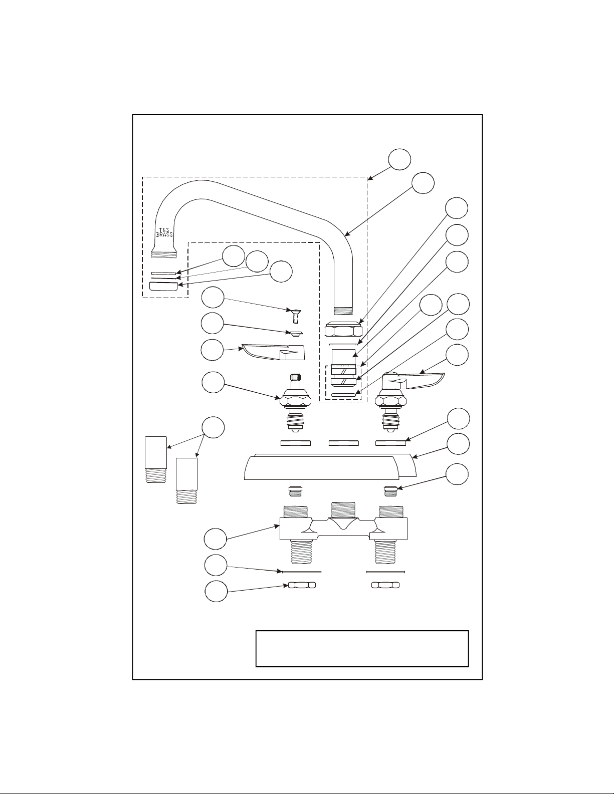
Exploded View
3
2
13
19181716151423
20
21
22
11
10
12
9
8
1
7
6
5
4
* Some items are listed for instructional purposes
and may not be sold as separate parts.
2
Page 3

Part Number Guide
Base Faucet Assemblies
Asm, Base Faucet (B-1100 - B-1103)
1 Base, Faucet *
2 Washer, Shank 000999-45
3 Locknut 002954-45
4 Seat 000763-20
5 Escutcheon, Body (3-1/2" - 4" Centers) 001258-40
Escutcheon, Body
6 Locknut, Cover Pl 000712-25
7 Asm, Spindle - LH 002709-40
Asm, Spindle - RH 002710-40
8 Spindle - LH 009754-25
Spindle - RH 009753-25
9 Handle - Cold 001636-45
Handle - Hot 001637-45
10 Index, Button - Blue 001660-45
Index, Button - Red 001661-45
11 Screw, Lever Handle 000922-45
23 * Optional Supply Connector Kit B-1100-K
* Order separately
(8" Centers)
001259-40
Nozzle Assemblies
12 Asm, Swing Nozzle - 6" 059X
Asm, Swing Nozzle - 8" 060X
Asm, Swing Nozzle - 10" 061X
Asm, Swing Nozzle - 12" 062X
Note: Item 15 and 19 are included when ordering nozzles
13 Nozzle (See Models) *
14 Nut, Swivel *
15 Washer, Swivel *
16 Swivel Piece *
17 Repair Parts Kit 011643-45
18 Sleeve, Swivel *
19 O-Ring *
20 Washer, Nozzle Tip 001048-45
21 Screen, Nozzle Tip 001323-45
22 Tip, Nozzle 000863-25
3
Page 4

General Instructions
Nozzle Installation:
Note: Nozzle should be installed first.
See diagram below:
1. Shut off water supply and drain
lines. Insert no.12 into no.1 and
rotate to front of sink.
2. Tighten no.14 firmly with a wrench.
12
Faucet Installation:
3. Drill (2) two holes into sink or
countertop where you are installing
no.1. Inlet spacing: 3-1/2”, 4” or 8”
center to center.
14
1
14
19
16, 18
1
Note: See repair kit 011643-45 for
replacement of no.18 and no.19.
16
18
19
sink
2
3
water
supply
water
supply
4. Place no.1 into pre-drilled holes.
Reinstall no.2 and no.3 back onto
no.1 shank under bottom of sink.
Tighten no.3 with a wrench.
5. Turn on water supply and check
for leaks.
4
Page 5

Instrucciones
Generales
Instalación De La Boquilla:
Instalación De La Canilla:
Nota: Las boquillas deben de ser
instaladas primero. Mire el dibujo
de abajo:
1. Cierre la fuente principal de agua y
desagüe las tuberias. Coloque la parte
No.12 entre la parte No.1 y gire hacia
el frente del lavatorio.
2. Aprete firmemente la parte No.14
con una llave.
12
14
19
16, 18
1
Nota: Refiérase al estuche de reparo
011643-45 para el reemplazo de las
partes No.18 y No.19.
3. Perfore (2) dos huecos en el
lavatorio o el mostrador donde la
parte No.1 será instalada. Aberturas
para las lineas de surtido: 9cm,
10cm o 20cm de centro a centro.
14
1
Lavatorio
2
3
Surtido
de agua
4. Coloque la parte No.1 dentro de las
perforaciones. Instale de nuevo las
partes No.2 y No.3 en el tronco de la
parte No.1 por debajo del lavatorio.
Aprete la parte No.3 con una llave.
5. Abra la fuente de agua e inspeccione
por filtraciones.
Surtido
de agua
16
18
19
5
Page 6

Instructions
Générales
L’Installation De L’Ajutage:
Noter: Les ajutages devoir être
installer au début. Voir le diagramme
ci-dessous:
1. Fermer la réserve de l’eau et
égoutter la tuyauterie. Insérer Nº.12
dans Nº.1 et tourner jusqu’ à la face de
l’évier.
2. Resserrer N.º14 fermement avec une
clef.
12
L’Installation Du Robinet:
3. Percer (2) deux trous dans le
comptoir ou l’évier ou vous aller
installer Nº.1. L’espacement de
l’arrivée: 9cm, 10cm ou 20cm centre
à centre.
14
1
14
19
16, 18
1
Noter: Voir la trousse à outils
011643-45 pour remplacer Nº.18 et
Nº.19.
16
18
19
l’évier
2
3
le tuyau qui
fournir l’eau
4. Mettre Nº.1 dans les trous déjà
préparés. Réinstaller Nº.2 et Nº.3 sur
la jambe au-dessous de l’évier.
Resserrer Nº.3 avec une clef.
5. Recommencer l’eau et vérifier s’il y
a des fuites.
6
Page 7

Allgemeine
Anleitungen
Schwenkhahninstallation:
Armatureninstallation:
Anmerkung: Der Schwenkhahn ist
als erstes zu installieren. Siehe
Zeichnung unten:
1. Wasserzufuhr abstellen und
Leitungen entleeren. Nr.12 in Nr.1
einfügen und in Richtung Vorderkante
des Beckens drehen.
2. Nr.14 mit einem Schraubenschlüssel
fest anziehen.
12
14
19
16, 18
1
Anmerkung: Siehe Instandsetzungssatz 011643-45 für Ersatz von Nr.18
und Nr. 19.
3. Zwei (2) Löcher in das Becken oder
die Abdeckplatte bohren, in die Nr.1
installiert wird. Entfernung der
Wasserzufuhren: 9cm, 10cm oder
20cm von Mitte zu Mitte.
14
1
Abdeckplatte
2
3
Wasserzufuhr
4. Nr.1 in die vorgebohrten Löcher
einsetzen. Nr.2 und Nr.3 auf der
Unterseite des Beckens wieder auf
den Schaft von Nr.1 aufsetzen. Nr.3
mit dem Schraubenschlüssel
anziehen.
5. Wasserzufuhr andrehen und auf
Lecks prüfen.
16
18
19
7
Page 8

RELATED T&S BRASS PRODUCT LINE
B-2347
Lavatory Faucet
with Hose Spray
T&S BRASS AND BRONZE WORKS, INC.
A firm commitment to application-engineered plumbing products
2 Saddleback Cove, P.O. Box 1088, T & S Brass-Europe
Travelers Rest, SC 29690 ‘De Veenhoeve’
Phone: (864) 834-4102 Oude Nieuwveenseweg 84
Fax: (864) 834-3518 2441 CW Nieuwveen
E-mail: tsbrass@tsbrass.com The Netherlands
 Loading...