

Page 1
EC-EASYWIRE
Installation Instructions
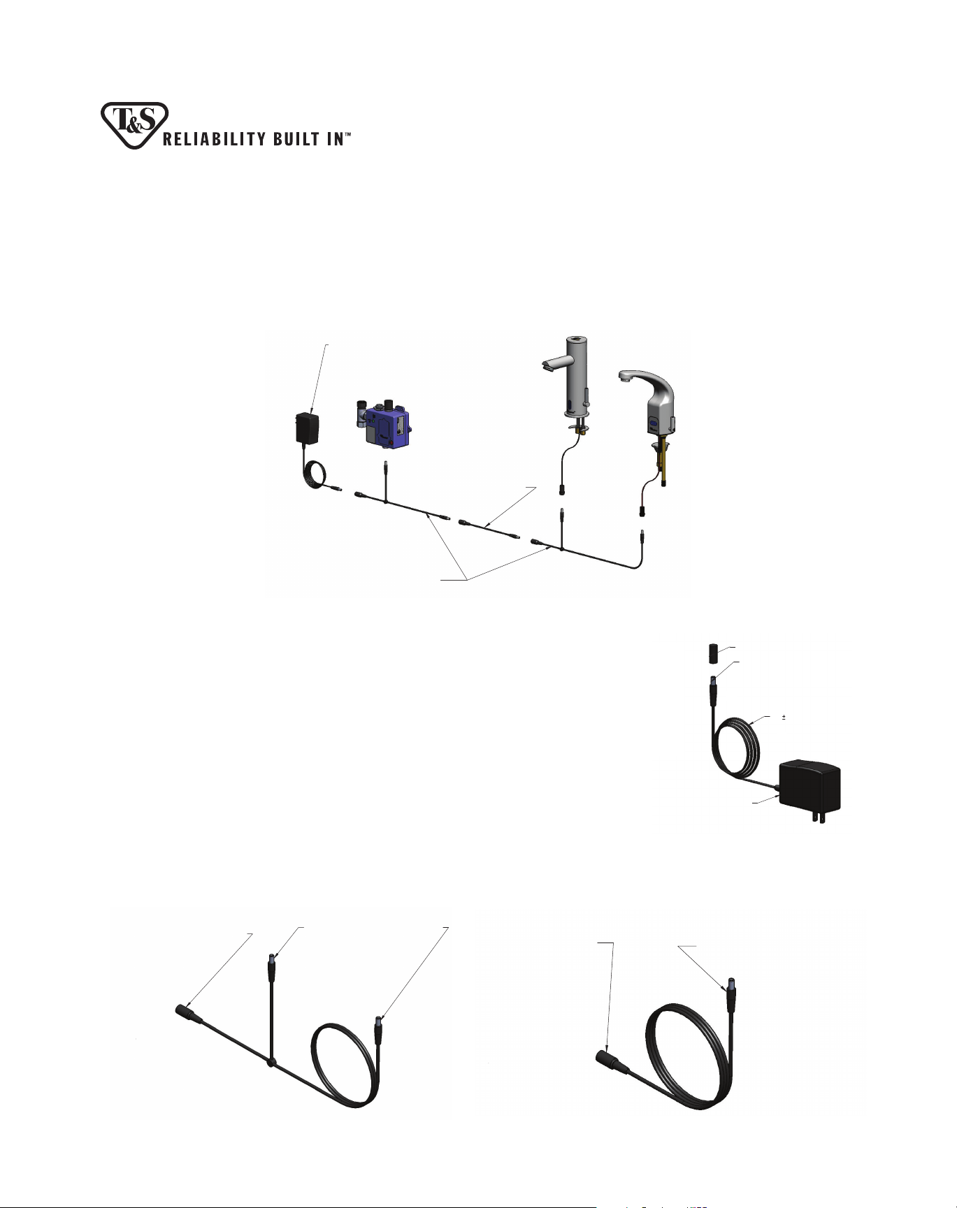
1. The EC-EASYWIRE kit along with multiple numbers of the EC-EASYWIRE4CC may be used to easily connect and
gang up to 8 of any of the ChekPoint electronic sensor faucet.
EC-EASYWIRE
100 - 240 VAC / 6.5 VDC, 2000mA
PLUG-IN TRANSFORMER CAPABLE OF
OPERATING UP TO (8) CHEKPOINT FAUCETS
EC-EASYWIRE5EXT
5 FT "EasyWire" EXTENSION
CABLES IF ADDITIONAL LENGTH
IS NEEDED FOR CONNECTIONS
EC-EASYWIRE4CC
4 FT "EasyWire" CONNECTOR CABLES
FOR QUICK UNDER-COUNTER CONNECTION
OF MULTIPLE FAUCETS (EXPOSED WIRING)
2. The EC-EASYWIRE kit consists of a 100-240 VAC transformer with a 76” long
power cord which plugs into a standard wall outlet (Figure 1).
3. The EC-EASYWIRE4CC kit consists of a 48” long power cord with 2 male
connectors and one female connector used to make the connections as noted
in the diagram in Figure 2. In utilizing the EASYWIRE method, multiple ECEASYWIRE4CC (ordered separately from the EC-EASYWIRE) must be used to
connect and gang the ChekPoint electronic sensor faucets. The multiple number
of EC-EASYWIRE4CC needed is one less than the number of ChekPoint faucets.
For example, if you are ganging eight (8) ChekPoint faucets together, you will
need to order seven (7) of the EC-EASYWIRE4CC and one (1) EC-EASYWIRE.
All ChekPoint models are able to be installed using the EASYWIRE method.
4. The EC-EASYWIRE5EXT kit is a 60” extension which can be used in between the
multiple EC-EASYWIRE4CC and also the controllers (Figure 3).
Female Plug Connects to ChekPoint
EasyWire AC Transformer or Other
ChekPoint EasyWire Connector Cables
Male Plugs Connect to ChekPoint
Control Modules and/or Other ChekPoint
EasyWire Connector Cables
Female Plug Connects to ChekPoint
EasyWire AC Transformer or ChekPoint
EasyWire Connector Cables
PROTECTIVE RUBBER CAP
ATTACHES TO CONNECTION PO
ON
CHEKPOINT SENSOR FAUCET
CONTROL MODULE
AND "EasyWire" CONNECTOR AN
EXTENSION CABLES
RD BOX
100-240 VAC TRANSFORMER
OUTPUT: 6.5 VDC, 2000mA
Male Plug Connects to ChekPoint
Control Module or ChekPoint EasyWire
Connector Cables
5" [1930mm] LONG
76"
POWER CORD
Figure 1
Figure 2 Figure 3
Page 2

SENSOR RANGE SETUP
Models with blue below deck control modules:
The sensor range is preset at the factory during assembly but can be further adjusted by using the steps below.
1. The sensing distance is adjustable from ¾” (2cm) to 6 11/16” (17cm). If there is a disruption in power, the sensor
range is saved and will revert to the last setting when power is restored.
2. The faucet sensor range is set by simply using the on/o button on the front of the control module. Do not
attempt to open the control module box.
3. Push and hold the on/o button; water will ow. After holding the button 5 to 7 seconds, the water ow will stop
and the red LED in the sensor lens will turn on solid.
4. Release the on/o button. The red LED will turn o signaling that the sensor is ready for set-up for the next 15
seconds.
5. Hold your hand still in front of the sensor at the desired sensor distance. The red LED will ash roughly 5 times
then remain on for 2 seconds indicating the new range has been set.
6. If step 5 is not done within 15 seconds, the red LED will blink quickly then stop indicating the sensor range has
NOT been changed. Start over at step 3 to change the sensor range.
EC-3122:
The EC-3122 uses a digital infrared, distance adjustable sensor which has a default range set at the factory. Should
this range need to be changed, follow the steps below. The sensing distance is adjustable from 3/4” (2cm) to 6
11/16” (17cm).
1. Shut o the water at the hot and cold supply stops.
2. Place the magnet provided to the upper right side of the sensor lens and move it closer to the lens.
3. Hold the magnet in place for 3 to 5 seconds. The red sensor LED will come on for set-up mode.
4. Remove the magnet and the sensor LED will go out.
5. Place a hand to the desired sensor range, hold in place and the LED will light up. (The recommended sensor
range is 3/8” [1 cm] in front of the spout).
6. Place the magnet to the right side of the sensor lens and move it closer to the lens until it starts blinking 5
times.
7. Remove your hand and magnet from the sensor area.
8. Turn on the water at the hot and cold supply stops.
9. Move a hand into the range set in step 5 which will activate the sensor (the LED will blink once) and water will
begin to ow.
10. If after removing your hand from the sensor range, the water continues to ow for longer than 2 seconds,
then the sensor range will need to be reset to a shorter distance.
sensor lens
magnet
Page 3

EC-3130 & EC-3132:
The EC-3130 and EC-3132 faucets have an adjustable sensor with a default range set at the factory. Should this range
need to be changed, follow the steps below and refer to Figure 4. The sensing distance is adjustable from 3/4” (2cm)
to 6 11/16” (17cm).
1. Place the magnet provided on the upper right corner of the sensor for 5 seconds. When the magnet is in place
the solenoid will open.
2. After 5 seconds when the solenoid closes and the LED turns on, remove the
magnet.
3. The LED will turn o indicating the sensor is now in set-up mode. Note: the sensor
will remain in set up mode for approximately 15 seconds. Then the LED will ash 3
times before the sensor range returns to its previous setting.
4. While in set-up mode, hold your hand at the desired distance from the sensor for 3
seconds. The LED will blink.
5. After the 3 seconds, the blinking LED will stay on for a few seconds then turn o .
sensor lens
magnet
6. When the LED turns o , the new range setting is saved
7. Even if the faucet loses power such as when the battery is replaced, the setting saved above will be kept.
Figure 4
Limited Three Year Warranty
T&S warrants to the original purchaser (other than for purposes of resale) that such product is free from defects in material and workmanship for a period of
three (3) years from the date of purchase. During this three-year warranty period, if the product is found to be defective, T&S shall, at its options, repair and/or
replace it. To obtain warranty service, products must be returned to...
T&S Brass and Bronze Works, Inc.
Attn: Warranty Repair Department
2 Saddleback Cove
Travelers Rest, SC 29690
Shipping, freight, insurance, and other transportation charges of the product to T&S and the return of repaired or replaced product to the purchaser are the
responsibility of the purchaser. Repair and/or replacement shall be made within a reasonable time after receipt by T&S of the returned product. This warranty
does not cover Items which have received secondary fi nishing or have been altered or modifi ed after purchase, or for defects caused by physical abuse to or
misuse of the product, or shipment of the products.
Any express warranty not provided herein, and any remedy for Breach of Contract which might arise, is hereby excluded and disclaimed. Any implied warranties
of merchantability or fi tness for a particular purpose are limited to three years in duration. Under no circumstances shall T&S be liable for loss of use or any
special consequential costs, expenses or damages.
Some states do not allow limitations on how long and implied warranty lasts or the exclusion or limitation of incidental or consequential damages, so the above
limitations or exclusions may not apply to you. Specifi c rights under this warranty and other rights vary from state to state.
Attention California Residents:
“WARNING: This product contains chemicals known to the State of California to cause cancer, and birth defects or other reproductive harm.”
T&S Brass and Bronze Works, Inc. · 2 Saddleback Cove · P.O. Box 1088 · Travelers Rest, SC 29690
www.tsbrass.com · E-mail: tsbrass@tsbrass.com · Phone (800) 476-4103 · Fax (800) 868-0084
West Coast Sales and Distribution · 4596 Ish Drive · Unit 220
Simi Valley, CA 93063 · Phone (800) 423-0150
098-017998-45 Rev. 2
Drawn TEH 10-21-15
Checked DMH 11-03-15
Approved JHB 11-25-15
 Loading...