

Page 1
Installation and
Maintenance
Limited Three Year Warranty
T&S warrants to the original purchaser (other
than for purposes of resale) that such product is
free from defects in material and workmanship for a
period of three (3) years from the date of purchase.
During this three-year warranty period, if the product
is found to be defective, T&S shall, at its options,
repair and/or replace it. To obtain warranty service,
products must be returned to...
T&S Brass and Bronze Works, Inc.
Attn: Warranty Repair Department
2 Saddleback Cove
Travelers Rest, SC 29690
Shipping, freight, insurance, and other
transportation charges of the product to T&S and
the return of repaired or replaced product to the
purchaser are the responsibility of the purchaser.
Repair and/or replacement shall be made within a
reasonable time after receipt by T&S of the returned
product. This warranty does not cover Items which
have received secondary fi nishing or have been
altered or modifi ed after purchase, or for defects
caused by physical abuse to or misuse of the
product, or shipment of the products.
Any express warranty not provided herein, and
any remedy for Breach of Contract which might
arise, is hereby excluded and disclaimed. Any
implied warranties of merchantability or fi tness for
a particular purpose are limited to three years in
duration. Under no circumstances shall T&S be
liable for loss of use or any special consequential
costs, expenses or damages.
Some states do not allow limitations on how
long and implied warranty lasts or the exclusion or
limitation of incidental or consequential damages,
so the above limitations or exclusions may not apply
to you. Specifi c rights under this warranty and other
rights vary from state to state.
Attention California Residents:
“WARNING: This product contains chemicals
known to the State of California to cause cancer,
and birth defects or other reproductive harm.”
Instructions
EC-3130
EC-3132
EC-3130 & EC-3132
ChekPoint
ABOVE DECK
ELECTRONIC FAUCETS
P/N: 098-018674-45 Rev.2
Date: 10-22-15
Drawn: TEH
Checked: DMH 11-03-15
Approved: JHB 11-25-15
Page 2
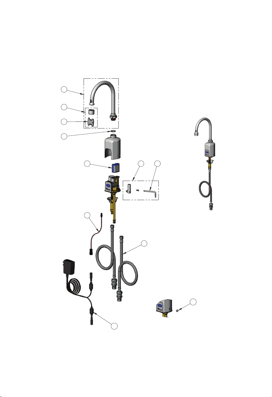
Exploded View
1
2
3
4
5 7
8
10
6
9
Shown with Optional
Pre-Set Temperature Plug
Figure 1A: EC-3130
Single Temperature
Faucet
11
Figure 1: EC-3130
2
Page 3
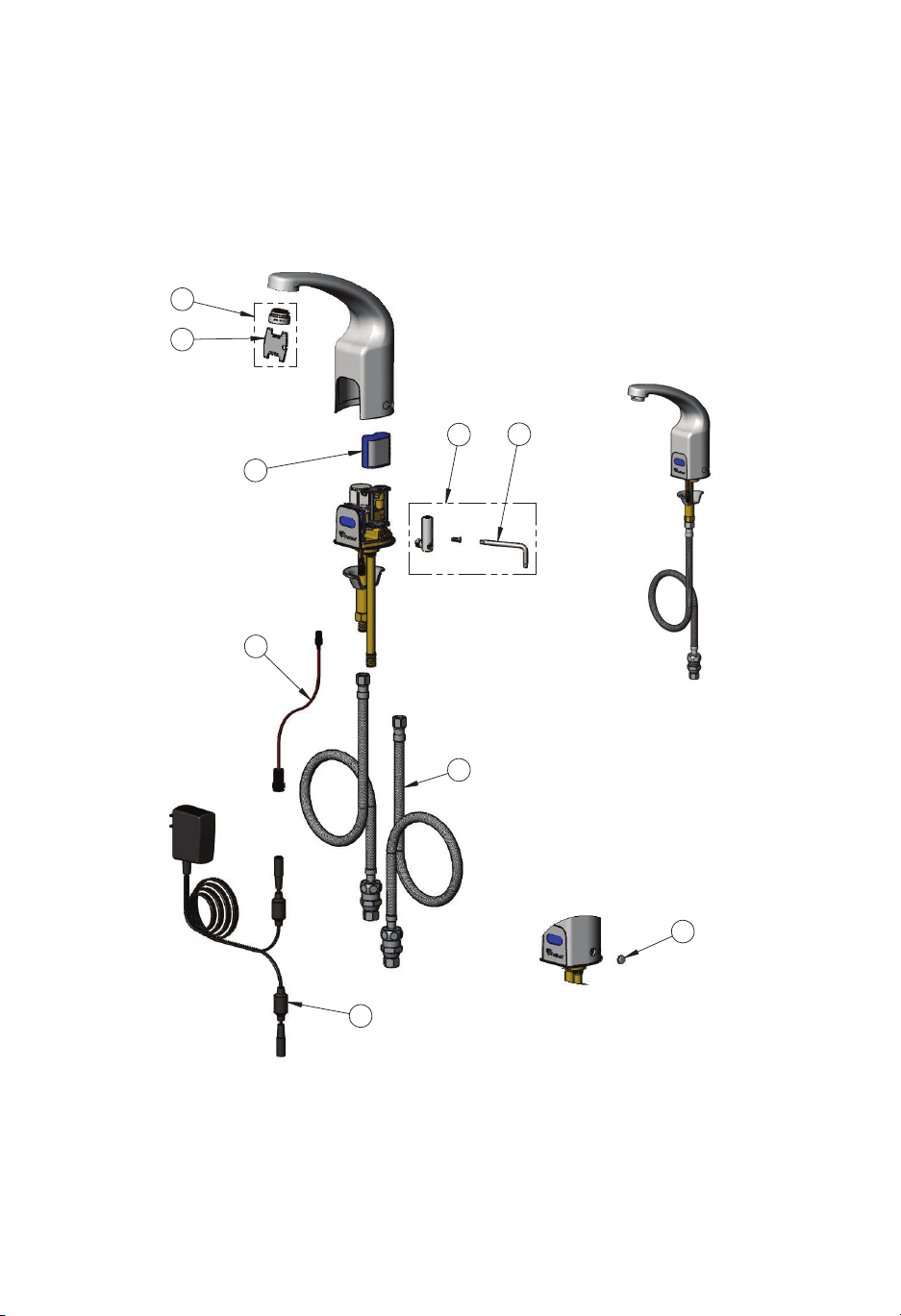
Exploded View
1
2
5
3
4
6
Figure 2A: EC-3132
Single Temperature
7
Faucet
9
8
Figure 2: EC-3132
3
Shown with Optional
Pre-Set Temperature Plug
Page 4

Part Number Guide
EC-3130 Electronic Faucet
1 Swivel Gooseneck w/ 2.2 GPM VR Aerator & Key 018490-40
2 2.2 GPM VR Aerator w/ Key B-0199-06
3 VR Aerator Key 015425-45
4 Star Washer, Anti-Rotation 014200-45
5 6V Lithium Battery, CR-P2 019087-45
6 Lever Asm & Body Screw Kit w/ L-Key 019082-45
7 Torx T-20 VR L-Key 018543-45
8 Auxiliary Power Connector Cable 019088-45
9 SS Flex Hose w/ Check Valve Adapter 018544-45
10 AC Transformer 5EF-0002
11 Body Plug, Pre-Set Temperature 019086-45
EC-3132 Electronic Faucet
1 2.2 GPM VR Aerator & Key 016355-45
2 VR Aerator Key 015425-45
3 6V Lithium Battery, CR-P2 019087-45
4 Auxiliary Power Connector Cable 019088-45
5 Lever Asm & Body Screw Kit w/ L-Key 019082-45
6 Torx T-20 VR L-Key 018543-45
7 SS Flex Hose w/ Check Valve Adapter 018544-45
8 AC Transformer 5EF-0002
9 Body Plug, Pre-Set Temperature 019086-45
4
Page 5

General Instructions
IMPORTANT:
· ALL ELECTRICAL WIRING IS TO BE
INSTALLED IN ACCORDANCE WITH
NATIONAL/LOCAL CODES AND REGULATIONS.
· ALL PLUMBING IS TO BE INSTALLED IN
ACCORDANCE WITH
APPLICABLE CODES AND REGULATIONS.
· USE APPROPRIATE PRECAUTIONS
WHILE CONNECTING TRANSFORMER TO
120 VAC POWER SOURCE.
· DO NOT PLUG TRANSFORMER INTO
POWER SOURCE (RECEPTACLE) UNTIL
ALL WIRING IS COMPLETED.
· FLUSH ALL WATER LINES UNTIL WATER
IS CLEAR BEFORE CONNECTING FAUCET
TO SUPPLY STOPS.
Tools Required For Installation of
Faucets
· 8” (200mm) adjustable wrench
· VR Torx wrench (included)
· Basin wrench
· Slotted screwdriver, 3/16”
· Phillips head screwdriver, #1
· Pliers
Prior to Installation:
Prior to installing the T&S ChekPoint
Series Faucet, install the items listed
below:
· Scrub or wash-up sink
· Drain line
· Hot and cold water supply lines &
stops.
(Supply stops must be furnished by
installer or purchased from T&S.)
Tighten compression ttings securely
on supply lines.
· (OPTIONAL) Provide electrical
receptacle within approximately 12’
from sink for plug-in transformer - 120
VAC, 2 amp service for each plug-in
transformer used.
Installation of EC-3130 & EC-3132
ChekPoint Faucets:
(Refer to Figures 1, 2 and 3)
The EC-3130 & EC-3132 ChekPoint
faucets have above deck sensor
electronics and temperature control.
Power is supplied by a 6V lithium
battery within the faucet body. Another
power option is an AC transformer
connected below the deck to a lead
terminal from the bottom of the faucet.
1. Drill a Ø 1 ¼” hole where the faucet
is to be installed. Maximum deck
thickness is 1 ½”.
2. Pull the battery saver strip coming
from the bottom of the faucet. The LED
light in the sensor lens will light up and
icker.
3. If using the AC transformer, connect
the auxiliary power connector cable to
the wire lead from the bottom of the
faucet.
4. Guide the supply tube, threaded
shank and wire lead through the hole in
the deck.
5. Secure from beneath using the
cupped washer and nut on the
threaded shank.
6. If adjusting the Auto Time Out and/
or Water Shut O Delay DIP switches,
refer to the section below, “SWITCH
SETTINGS.”
7. If installing the AC transformer, refer
to the section below, “TRANSFORMER
OPTION.”
5
Page 6

General Instructions
8. For a mixing faucet with 2 inlets, connect the check valve adapter end of the
exible supply hoses to the supply stops. Connect the other end of the supply
hose to the corresponding hot supply threaded shank and cold supply tube. Do not
overtighten.
9. For a single temperature faucet with one inlet shank, connect the check valve
adapter end of one exible supply hose to the single temperature water supply.
Connect the other end of the supply hose to the single inlet shank.
10. Turn on supply stops and check for leaks.
11. To test the sensor eye on/o function and switch settings (if set), place your hand
2 to 3 inches in front of the sensor. The LED will blink once and water will start to
ow.
12. Remove your hand from the area. If water does not stop owing within 2 seconds
or according the to the Water Shut O Delay set by SW(5) and SW(6), then the
sensor range will need adjusting (refer to “INSTRUCTIONS FOR SETTING THE SENSOR
RANGE”).
Figure 3
POINT-OF-USE TEMPERATURE ADJUSTMENT:
1. Push the lever on the right side towards the back for colder water.
2. Pull the lever towards the front for hotter water.
PRE-SET WATER TEMPERATURE ADJUSTMENT:
1. Using the L-Key provided, remove the handle and body screws.
2. Remove the temperature lever and adapter from the faucet body. Note: the adapter
has an o-ring seal and may require pliers to pull out from the body. Protect the
chrome nish on the adapter from the jaws of the pliers.
3. Using a at screwdriver, turn the brass spindle accessible through the hole where
the adapter was removed to adjust the water temperature to the desired setting:
clockwise for colder, counter clockwise for hotter.
4. After setting water temperature, shut-o the water supply at the supply stops.
6
Page 7

General Instructions
5. Remove the faucet body from the base by
pulling the body straight up.
6. Install the chrome body plug into the hole
from the inner side of the body as shown
below. The smooth face of the plug will be the
exposed size. Press the plug until bottomed.
7. Carefully reinstall the body straight down
onto the base.
8. Reinstall the body screw.
9. Turn on the supply stops.
SWITCH SETTINGS:
The EC-3130 and EC-3132 ChekPoint controller o ers settable water ow control
adjustment selections. These selections are set by con guring a bank of DIP switches
located behind the sensor to the settings shown on the tables below.
To access the DIP switches:
1. Shut-o the water supply at the supply stops.
2. Using the L-Key provided, remove the handle and body screws. If the pre-set
temperature plug is installed it does not need to be removed.
3. Remove the temperature lever and adapter from the faucet body. Note: the adapter
has an o-ring seal and may require pliers to pull out from the body. Protect the
chrome nish on the adapter from the jaws of the pliers.
4. Remove the faucet body from the base by pulling the body straight up.
5. Remove the battery to access the bank of DIP switches.
6. Set the DIP switches to the desired
settings described on page 8.
7. Replace battery.
8. Carefully reinstall the body straight
down onto the base.
9. Reinstall the lever handle assembly
and body screw.
Figure 4
body plug
Figure 5:
Access to Dip Switch
Settings
7
Page 8
General Instructions
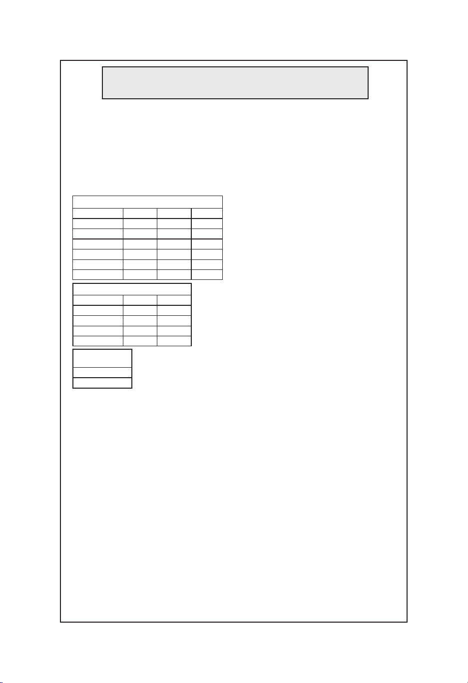
AUTO TIME-OUT ADJUSTMENT (SWITCHES 1-3)
• The ChekPoint controller provides six periods to select from for shutting o the
water when the object is left in front of the electronic eye. The time periods to
select from are: 15 seconds, 30 seconds, 45 seconds, 60 seconds, 3 minutes and
20 minutes. The default setting is 15 seconds.
Note: The chart below indicates the switch positions required for each auto time-out mode.
Auto Time Out Selection
PERIOD
15 seconds
30 seconds
45 seconds
60 seconds
3 minutes
20 minutes
Water Shut Off Delay Selection
PERIOD
1 seconds
10 seconds
15 seconds
30 seconds
Auto Flush Mode
SW (4)
ON - (Enable)
OFF - (Disable)
SW(1)
OFF
OFF
OFF
OFF
ON
ON
SW(5)
OFF
OFF
ON
ON
SW(2)
OFF
OFF
ON
ON
OFF
OFF
SW(6)
OFF
ON
OFF
ON
SW(3)
OFF
OFF
OFF
WATER SHUT-OFF DELAY
ADJUSTMENT (SWITCHES 5 & 6)
• The ChekPoint controller provides
ON
ON
ON
four periods to select from for
shutting o the water when the
object is removed from in front of the
electronic eye. The time periods to
select from are: 1 second, 10 seconds,
15 seconds, and 30 seconds. The
default setting is 1 second.
AUTO-FLUSH (SWITCH 4)
• The ChekPoint controller o ers the
option to select the Auto Flush mode
in switch 4 position. When enabled,
the controller will ush the ChekPoint faucet every 12 hours for 25-30
seconds when the faucet is not used.
Default setting from the factory is in
the “o ” position.
TRANSFORMER OPTION:
IMPORTANT: DO NOT plug the transformer into a receptacle until all wiring has been
completed. This type of transformer is designed to be plugged into a 120 VAC
wall receptacle. The transformer is supplied with a 12 foot cable. When used in
conjunction with the battery, the transformer will become the primary power source.
Plug the transformer cable and auxiliary power connector cable into the wire lead
coming from the bottom of the EC-3130 or EC-3132 faucet body.
Note: For the Hydro Generator (EC-HYDROGEN) power option, refer to the instruction
manual in the EC-HYDROGEN kit ordered separately. For hard wiring and hard wire
ganging (EC-HARDWIRE) and easy-wire (EC-EASYWIRE) ganging power options , refer to
the instruction manual in each respective kit when ordered separately.
LOW BATTERY INDICATOR AND BATTERY REPLACEMENT:
• A red ashing LED in the sensor indicates a low battery.
• A constant on LED with no water ow indicates a dead battery.
8
Page 9

General Instructions
To replace the battery:
1. Shut-o the water supply at the supply stops.
2. Using the L-Key provided, remove the handle and body screws. If the pre-set
temperature plug is installed it does not need to be removed.
3. Remove the Temperature Lever and adapter from the faucet body. Note: the
adapter has an o-ring seal and may require pliers to pull out from the body. Protect
the chrome nish on the adapter from the jaws of the pliers.
4. Remove the faucet body from the base by pulling the body straight up.
5. Remove and replace the battery.
6. Carefully reinstall the body straight down onto the base.
7. Reinstall the lever handle assembly, if used, and body screw.
8. Open the supply stops.
INSTRUCTIONS FOR SETTING THE SENSOR RANGE:
The EC-3130 and EC-3132 faucets have an adjustable sensor with a default range set at
the factory. Should this range need to be changed, follow the steps below and refer to
Figure 6. The sensing distance is adjustable from 3/4” (2cm) to 6 11/16” (17cm).
1. Place the magnet provided on the upper right corner of the sensor for 5 seconds.
When the magnet is in place the solenoid will open.
2. After 5 seconds when the solenoid closes and the LED turns on, remove the magnet.
3. The LED will turn o indicating the sensor is now in set-up mode. Note: the sensor
will remain in set up mode for approximately 15 seconds. Then the LED will ash 3
times before the sensor range returns to its previous setting.
4. While in set-up mode, hold your hand at the desired distance from the sensor for 3
seconds. The LED will blink.
5. After the 3 seconds, the blinking LED
will stay on for a few seconds then turn
o .
6. When the LED turns o , the new
range setting is saved
7. Even if the faucet loses power such as
when the battery is replaced, the setting
saved above will be kept.
Figure 6
sensor lens
9
magnet
Page 10

General Instructions
TROUBLESHOOTING GUIDE
PROBLEM
No Water When Activated
Red LED in electronic eye
POSSIBLE CAUSE/SOLUTION
If red LED stays on or is ashing:
1. Replace batteries.
Very Low Flow or Slow Dribble
False Triggering
(Unit goes on by itself)
Continues to Run
(Even after power to faucet has been
reconnected)
1. Check supply stop(s); open if closed.
2. Debris in supply hose lter washers
in 1/2” NPSM swivel end; remove, clean
and reinstall.
3. Debris in aerator or spray head;
remove, clean and reinstall
1. Check surroundings for factors that
can contribute to the false triggering;
for example, bright lights, highly
re ective surfaces, sunlight, etc.
2. Range too long; decrease sensor
range.
1. Debris in solenoid valve, won’t close
properly. Contact factory.
10
Page 11

RELATED T&S BRASS PRODUCT LINE
EC-3130-4DP
ChekPoint Electronic Faucet, Single
Hole Deck Mount with 4” Deck Plate
EC-3132-HG
ChekPoint Electronic Faucet, Single Hole
Deck Mount, Hydro-Generated Powered
EC-3132-VF05
ChekPoint Electronic Faucet, Single Hole Deck
Mount, 2.2 GPM Vandal Resistant Aerator,
Optional Vandal Resistant 0.5 GPM Spray Device
T&S BRASS AND BRONZE WORKS, INC.
A fi rm commitment to application-engineered plumbing products
2 Saddleback Cove, P.O. Box 1088, T & S Brass-Europe
Travelers Rest, SC 29690 ‘De Veenhoeve’
Phone: (864) 834-4102 Oude Nieuwveenseweg 84
Fax: (864) 834-3518 2441 CW Nieuwveen
E-mail: tsbrass@tsbrass.com The Netherlands
 Loading...