

Page 1
Limited One Year Warranty
T&S warrants to the original purchaser (other than
for purposes of resale) that such product is free from
defects in material and workmanship for a period of
one (1) year from the date of purchase. During this
one-year warranty period, if the product is found to
be defective, T&S shall, at its options, repair and/
or replace it. To obtain warranty service, products
must be returned to...
T&S Brass and Bronze Works, Inc.
Attn: Warranty Repair Department
2 Saddleback Cove
Travelers Rest, SC 29690
Shipping, freight, insurance, and other transportation charges of the product to T&S and the return
of repaired or replaced product to the purchaser are
the responsibility of the purchaser. Repair and/or
replacement shall be made within a reasonable time
after receipt by T&S of the returned product. This
warranty does not cover Items which have received
secondary finishing or have been altered or modified after purchase, or for defects caused by physical abuse to or misuse of the product, or shipment
of the products.
Any express warranty not provided herein, and
any remedy for Breach of Contract which might arise,
is hereby excluded and disclaimed. Any implied
warranties of merchantability or fitness for a particular purpose are limited to one year in duration. Under
no circumstances shall T&S be liable for loss of
use or any special consequential costs, expenses
or damages.
Some states do not allow limitations on how long
and implied warranty lasts or the exclusion or limitation of incidental or consequential damages, so
the above limitations or exclusions may not apply
to you. Specific rights under this warranty and other
rights vary from state to state.
P/N: 098-003119-45 Rev.2
Date: 980410
Drawn: CW
Checked:
Approved:
MW 6-16-98
MAB 6-10-98
Installation and
Maintenance
Instructions
Fume Hood Valves
BL-4705 Series
Deutsch: Installations- und
Wartungsanleitungen
Español: la Instalación y las
Instrucciones de
Mantenimiento
Français: les Instructions
d’Installation et
d’Entretien
Page 2
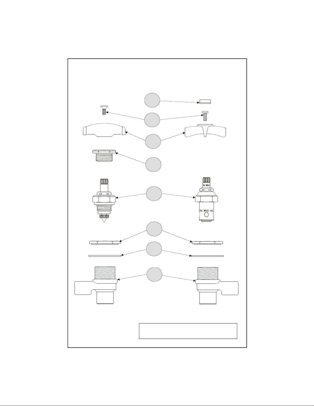
Exploded View
8
7
6
5
4
3
2
1
* Some items are listed for instructional
purposes and may not be sold as separate parts.
Page 3

Part Number Guide
Fume Hood Valve Assemblies
Asm, Fume Hood Valve (Air & Gas) (BL-4705-01)
Asm, Fume Hood Valve (Water) (BL-4705-02)
Asm, Fume Hood Valve (Steam) (BL-4705-03)
1 Body, Valve *
2 Lock-Washer *
3 Lock-Nut *
4 Asm, Spindle (BL-4705-01, -02) 005960-40
Asm, Spindle (BL-4705-03) 110A
5 Seat, Removable 000529-20
6 Handle, Stem 001149-20
Handle 000059-40
7 Screw, Handle (Bl-4705-01, -02) 000925-45
Screw, Handle (Bl-4705-03) 000922-45
8 Index Button, Snap-in 001197-45
Page 4

General Instructions
Installation:
Note: The BL-4705-01 used for air and gases, BL-4705-02 used for water (eterna), BL-
4705-03 used for steam.
1. Drill one (1) 1-3/16” diameter hole in sheet metal fume hood face at desired
mounting location.
2. Unscrew no.4 with a wrench and remove from no.1.
1
3. Unscrew and remove no.3 from no.1. Place threaded end of no.1 thru prepared
hole location.
3
4
3
1
2
sheet metal
fume hood
4. Place no.3 onto threaded end of no.1 and tighten.
5. Apply teflon tape or pipe joint compound to threads of no.1 and connect
supply pipe and outlet pipe to no.1.
6. Reinstall no.4 (with no.6 assembled)
into no.1.
BL-4705-03
7. Turn on (air,
water, or gas)
inlet
4
6
and check for
leaks.
outlet
BL-4705-01
BL-4705-02
1
Page 5

Instrucciones
Generales
Instalación:
Nota: La parte BL-4705-01 es usada para aire y gases, la BL-4705-02 es usada para
agua (eterna), la BL-4705-03 es usada para vapor.
1. Perfore (1) un hueco de 3cm de díametro en el metal laminado en el frente de la
capota para humo en el local deseado para la instalación.
2. Destornille la parte No.4 con una llave y remuevala de la parte No.1.
1
3. Destornille y remueva la parte No.3 de la parte No.1, coloque el extremo con
rosca de la parte No.1 a través del hueco preparado de ante mano.
3
4
3
1
4. Coloque la parte No.3 en el extremo con rosca de la parte No.1 y aprete.
5. Aplique cinta para rosca de tubería o compuesto de coyuntura a las rosca de la
parte No.1 y conecte el tubo surtidor y el tubo de salida a la parte No.1.
6. Instale de nuevo la parte No.4
(con la parte No.6 ensamblada)
entre la parte No.1.
7. Abra (aire,
agua o gas) e
inspeccione por
filtraciones.
Entrada
Salida
1
2
Metal laminado
Capota para humo
4
BL-4705-03
6
BL-4705-01
BL-4705-02
Page 6

Instructions
Générales
L’Installation:
Noter: On utiliser BL-4705-01 pour l’air et la gaz, BL-4705-02 pour l’eau (eterna), et
BL-4705-03 pour le vapeur.
1. Percer un (1) trou avec un diamètre de 3cm dans le capot de vapeur en tôle òu
vous aller installer l’élément.
2. Dévisser Nº.4 avec une clef et enlever de Nº.1.
1
3. Dévisser et enlever Nº.3 de Nº.1. Mettre l’extrémité avec les filets à travers le
trou déjà préparé.
3
4
3
1
4. Mettre Nº.3 sur l’extrémité avec les filets de Nº.1 et resserrer.
5. Appliquer le ruban en Téflon ou le composé pour les tuyaux aux filets de Nº.1
et attacher le tuyau d’approvisionnement et le tuyau de sortie à Nº.1.
6. Réinstaller Nº.4 (avec Nº.6 déjà
assemblé) dans Nº.1.
7. Recommencer (l’air
ou le gaz, l’eau
ou le vapeur)
et vérifier s’il y
a des fuites.
l’arrivée
la sortie
1
2
le capot de
vapeur en tôle
4
BL-4705-03
6
BL-4705-01
BL-4705-02
Page 7

Allgemeine
Anleitungen
Installation:
Anmerkung: BL-4705-01 ist für Luft und Gase, BL-4705-02 für Wasser, BL-4705-03
für Dampf.
1. Ein Loch mit 3cm Durchmesser an der gewünschten Anbringungsstelle in die
Vorderseite der Blechabzughaube bohren.
2. Nr.4 mit einem Schraubenschlüssel losschrauben und von Nr.1 entfernen.
1
3. Nr.3 von Nr.1 losschrauben und entfernen. Das Gewindeende von Nr.1 durch
das Loch geben.
3
4
3
1
4. Nr.3 auf das Gewindeende von Nr.1 aufsetzen und anziehen.
5. Teflonband oder Rohrdichtmasse auf das Gewinde von Nr.1 auftragen und
Wasserzufuhrrohr und Auslaufrohr mit Nr.1 verbinden.
6. Nr.4 (mit Nr.6 in zusammengesetztem Zustand)
wieder in Nr.1 installieren.
7. Luft-, Wasseroder Gaszufuhr
andrehen und
auf Lecks
Prüfen.
Zufuhr
Ausfluß
1
2
Blech
Abzughaube
4
BL-4705-03
6
BL-4705-01
BL-4705-02
Page 8

RELATED T&S BRASS PRODUCT LINE
BL-4700
Remote Control
Straight Valve Unit
T&S BRASS AND BRONZE WORKS, INC.
A firm commitment to application-engineered plumbing products
2 Saddleback Cove, P.O. Box 1088, T & S Brass-Europe
Travelers Rest, SC 29690 ‘De Veenhoeve’
Phone: (864) 834-4102 Oude Nieuwveenseweg 84
Fax: (864) 834-3518 2441 CW Nieuwveen
E-mail: tsbrass@tsbrass.com The Netherlands
 Loading...