

Page 1
Limited One Year Warranty
T&S warrants to the original purchaser (other than
for purposes of resale) that such product is free from
defects in material and workmanship for a period of
one (1) year from the date of purchase. During this
one-year warranty period, if the product is found to
be defective, T&S shall, at its options, repair and/
or replace it. To obtain warranty service, products
must be returned to...
T&S Brass and Bronze Works, Inc.
Attn: Warranty Repair Department
2 Saddleback Cove
Travelers Rest, SC 29690
Shipping, freight, insurance, and other transportation charges of the product to T&S and the return
of repaired or replaced product to the purchaser are
the responsibility of the purchaser. Repair and/or
replacement shall be made within a reasonable time
after receipt by T&S of the returned product. This
warranty does not cover Items which have received
secondary finishing or have been altered or modified after purchase, or for defects caused by physical abuse to or misuse of the product, or shipment
of the products.
Any express warranty not provided herein, and
any remedy for Breach of Contract which might arise,
is hereby excluded and disclaimed. Any implied
warranties of merchantability or fitness for a particular purpose are limited to one year in duration. Under
no circumstances shall T&S be liable for loss of
use or any special consequential costs, expenses
or damages.
Some states do not allow limitations on how long
and implied warranty lasts or the exclusion or limitation of incidental or consequential damages, so
the above limitations or exclusions may not apply
to you. Specific rights under this warranty and other
rights vary from state to state.
P/N: 098-009431-45 Rev.1
Date: 980508
Drawn: CW
Checked:
Approved:
MW 6-10-98
MAB 6-10-98
Installation and
Maintenance
Instructions
B-2346 SINK FAUCET
(with diverter, vacuum
breaker, stainless steel
hose and spray)
Deutsch: Installations- und
Wartungsanleitungen
Español: la Instalación y las
Instrucciones de
Mantenimiento
Français: les Instructions
d’Installation et
d’Entretien
Page 2
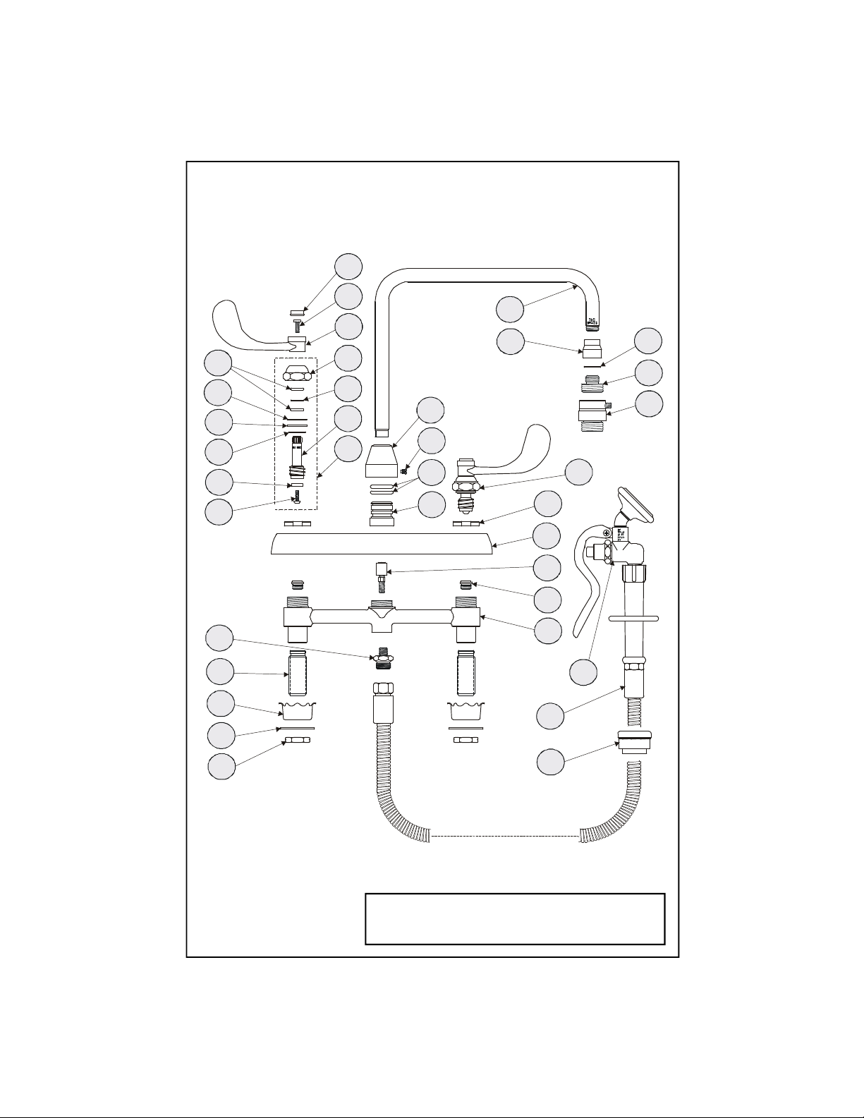
Exploded View
33
32
31
28
20
21
22
23
24
25
27
26
19
18
17
16
6
7
8
9
14
13
12
11
29
30
15
5
4
3
2
1
34
35
10
36
* Some items are listed for instructional purposes
and may not be sold as separate parts.
Page 3

Part Number Guide
Base Faucet Assemblies
1 Body, Faucet *
2 Seat 000763-20
3 Valve, Diverter Piston 002338-45
4 Escutcheon, Body 001259-40
5 Locknut, Cover Plate 000712-25
6 Adapter, 1/8 MA x 3/8 NPSM *
7 Shank, Faucet *
8 Washer, Rosette 001000-45
9 Washer, Shank 000999-45
10 Locknut, 1/2 NPSM Shank 001801-20
11 Adapter, Diverter 001484-20
12 O-Ring, Center Body 001069-45
13 Screw, Diverter Cover 001486-45
14 Cover, Diverter *
15 Asm, Spindle and Handle - RH *
Asm, Spindle and Handle - LH *
16 Asm, Spindle - RH 009423-40
Asm, Spindle - LH 009424-40
17 Spindle - RH 000800-25
Spindle - LH 000801-25
18 Washer, Bonnet Style 009752-45
19 Bonnet 009749-25
20 O-Ring, Diverter Stem 001075-45
21 Washer, S/S, Bonnet 002726-45
22 Washer, Bonnet 001047-45
23 Washer, Bonnet 000986-45
24 Seat Washer, Teflon 001136-45
25 Screw, Seat Washer 000933-45
26 Handle, Wrist Action 4" 000078-45
27 Screw, Lab Handle 000922-45
28 Index, Button - Snap-in, Cold, Blue 001686-45
Index, Button - Snap-in, Hot, Red 001194-45
29 Nozzle, Swivel *
30 Adapter, Bell, 5/8-27 x 3/8 FE 000557-25
31 Washer, GN Tip 001043-45
32 Adapter, 3/4 GH MA x 3/8 NPSM *
33 Vacuum Breaker, 3/4 WTS GH *
34 Asm, Spray Valve 002853-40
35 Asm, Flex Hose 009428-40
36 Protective Flange B-KF
Page 4

General Instructions
Installation: Nozzle
1”
Ø
1-9/16” Ø1-1/4 Ø8”4” Min.for hose& spray4
”
Note: Nozzle should be installed first.
See diagram below:
1. Place no.14 over no.11. Make sure
no.12 is in place. Insert no.13 into
side of no.14. Do not tighten.
2. Apply teflon tape or pipe joint
compound to threaded end of no.29.
Screw no.29 into no.14, rotate so that
no.29 is facing front, tighten no.13.
1,4
10
8
9
water
supply
7
sink
water
supply
29
14
11, 12
13
Installation: Faucet
3. Shut off water supply and drain
lines. Drill (4) four holes (3 holes for
B-2346), into countertop where you
are installing no.1.
faucet body
5. Reinstall no.8, no.9 and no.10 onto
no.7 under bottom of sink. Connect
water supply to each no.7.
6. Tighten no.10 with a wrench.
Spray Hose/Diverter Installation:
7. Disassemble no.36 into two pieces,
place no.36 into hole, reattach bottom
half of no.36 to first half. Tighten by
hand under bottom of sink.
8. Apply teflon tape to end of no.35.
Place no.35 through no.36.
9. To attach no.35 to no.1, screw no.6
into no.35, then attach no.6 to no.1.
34,35
1
sink
4. Place no.1 into the (3) three predrilled mounting holes.
6
36
35
10. Turn on water supply and check
for leaks.
Page 5

Instrucciones
Generales
Instalación: Boquilla
2.5cm Ø
3.2cm Ø
20cm
10cm
Nota: Las boquillas deben de ser
instaladas primero. Mire el dibujo
de abajo:
1. Coloque la parte No.14 sobre la
parte No.11. Asegúrese que la parte
No.12 esté bien situada. Insarte la
parte No.13 entre el lado de la parte
No.14. No lo aprete.
2. Aplique cinta para rosca de tubería
o compuesto de coyuntura al extremo
con rosca de la parte No.29. Atornille
la parte No.29 en la parte No.14, gire
de modo que la parte No.29 esté
horientada hacia el frente, aprete la
parte No.13.
29
Lavatorio
Lineas de
surido
10
1,4
8
9
7
5. Instale de nuevo las partes No.8, 9
y 10 entre la parte No.7 debajo del
fondo del lavatorio. Conecte el surtido
de agua a ambas partes de la parte
No.7.
6. Aprete la parte No.10 con una llave.
Instalación Del Desviador Para La
Manguera Roceadora:
14
11, 12
13
Instalación: Canilla
3. Cierre el surtido de agua y desagüe
las tuberias. Perfore (4) cuatro huecos
(3 huecos para el modelo B-2346), en
el mostrador donde será instalada la
parte No.1.
Canilla
10cm
4. Coloque la parte No.1 entre los tres
(3) huecos preparados anteriormente.
Para manguera
roceadora
4 cm Ø
7. Desarme la parte No.36 en dos
piezas, coloque la parte No.36 dentro
del hueco, junte de nuevo la mitad
posteriora de la parte No.36 a la primer
parte. Aprete a mano por debajo del
fondo del lavatorio.
8. Aplique cinta para rosca de tubería
al extremo de la parte No.35. Coloque
la parte No.35 a través de la parte
No.36.
9. Para unir la parte No.35 a la parte
No.1, atornille la parte No.6 entre
la parte No.35 a través
de la parte No.36.
1
Lavatorio
6
34,35
36
35
10. Abra la fuente de agua e
inspeccione por filtraciones.
Page 6

Instructions
Générales
L’Installation De L’Ajutage:
2.5cm Ø
3.2cm Ø
20cm
10cm Min.
Noter: L’ajutage devoir être installer
au début. Voir le diagramme cidessous:
1. Mettre Nº.14 sur Nº.11. Soyez
certain que Nº.12 être à sa place.
Insérer Nº.13 dans le côté de Nº.14.
Ne le resserrer pas.
2. Appliquer le ruban en Téflon ou le
composé pour les tuyaux à l’extrémité
avec les filets de Nº.29. Visser Nº.29
dans Nº.14, tourner jusqu’à Nº.29 être
en face, resserrer Nº.13.
29
1,4
8
9
10
les tuyaux
qui fournir
7
l’eau
l’évier
les tuyaux
qui fournir
l’eau
5. Réinstaller Nº.8, Nº.9 et Nº.10 sur
Nº.7 au-dessous-de l’évier. Brancher le
tuyau qui fournir l’eau à chaque Nº.7.
6. Reserrer Nº.10 avec une clef.
14
11, 12
13
L’Installation: Du Robinet
3. Fermer la réserve de l’eau et
égoutter la tuyauterie. Percer (4)
quatre trous (3 trous pour B-2346)
dans le comptoir où vous aller
installer Nº.1.
le robinet
10cm
4cm Ø
4. Mettre Nº.1 dans les trois trous
déjà préparés.
Le Tuyau De Jet/ L’Installation
D’Aiguillage:
7. Désassembler Nº.36 en deux
morceaux, mettre Nº.36 dans le trou,
réattacher la moitié du bas à la
première moitié. Resserrer par le main
au-dessous-de l’évier.
8. Appliquer le ruban en Téflon a
l’extrémité avec les filets de Nº.35.
Mettre Nº.35 à travers Nº.36.
9. Pour attacher Nº.35 à Nº.1, visser
Nº.6 dans Nº.35, puis attacher Nº.6 à
Nº.1.
1
6
10. Recommencer l’eau et vérifier s’il
y a des fuites.
34, 35
l’évier
36
35
Page 7

Allgemeine
Anleitungen
Schwenkhahninstallation:
2,5cm Ø
3,2cm Ø
20cm
mindestens 10cm
Anmerkung: Den Schwenkhahn als
erstes installieren:
1. Nr.14 auf Nr.11 aufsetzen.
Sicherstellen, daß Nr.12
ordnungsgemäß installiert ist. Nr.13
seitlich in Nr.14 einfügen. Nicht
anziehen.
2. Teflonband oder Rohrdichtmasse
auf das Gewinde von Nr.29 auftragen.
Nr.29 in Nr.14 schrauben, Nr.29 in
Richtung Vorderseite des Spültisches
drehen, Nr.13 anziehen.
29
1,4
8
9
10
Wasserleitung
Wasserleitung
7
Spültisch
5. Nr.5, 9 und 10 auf der Unterseite
des Spültisches wieder auf Nr.7
installieren.
6. Nr.10 mit Schraubenschlussel
anziehen.
14
11, 12
13
Armatureninstallation:
3. Wasserzufuhr abstellen und
Leitungen entleeren. Vier (4) Löcher
(drei für B-2346) in die Abdeckplatte
bohren wo Nr.1 installiert wird.
Armaturrumpf
10cm
4 cm Ø
4. Nr.1 in die drei (3) Bohrlöcher
einsetzen.
Installation des Brausenschlauchs
und Umstellers:
7. Nr.36 in zwei Teile
auseinandernehmen, Nr.36 in das
Loch stecken, die untere Hälfte von
Nr.36 mit der anderen Hälfte
verbinden. Mit der Hand unter dem
Spültisch anziehen.
8. Das Ende von Nr.35 mit Teflonband
umwickeln. Nr.35 durch Nr.36
stecken.
9. Um Nr.35 mit Nr.1 zu verbinden,
Nr.6 in Nr.35 einschrauben, dann Nr.6
mit Nr.1 verbinden.
1
6
34, 35
35
Spültisch
36
10. Wasserzufuhr andrehen und auf
Lecks prüfen.
Page 8

RELATED T&S BRASS PRODUCT LINE
B-2347
Lavatory Faucet
with Hose Spray
T&S BRASS AND BRONZE WORKS, INC.
A firm commitment to application-engineered plumbing products
2 Saddleback Cove, P.O. Box 1088, T & S Brass-Europe
Travelers Rest, SC 29690 ‘De Veenhoeve’
Phone: (864) 834-4102 Oude Nieuwveenseweg 84
Fax: (864) 834-3518 2441 CW Nieuwveen
E-mail: tsbrass@tsbrass.com The Netherlands
 Loading...