

Page 1
Limited One Year Warranty
T&S warrants to the original purchaser (other than
for purposes of resale) that such product is free from
defects in material and workmanship for a period of
one (1) year from the date of purchase. During this
one-year warranty period, if the product is found to
be defective, T&S shall, at its options, repair and/
or replace it. To obtain warranty service, products
must be returned to...
T&S Brass and Bronze Works, Inc.
Attn: Warranty Repair Department
2 Saddleback Cove
Travelers Rest, SC 29690
Shipping, freight, insurance, and other transportation charges of the product to T&S and the return
of repaired or replaced product to the purchaser are
the responsibility of the purchaser. Repair and/or
replacement shall be made within a reasonable time
after receipt by T&S of the returned product. This
warranty does not cover Items which have received
secondary finishing or have been altered or modified after purchase, or for defects caused by physical abuse to or misuse of the product, or shipment
of the products.
Any express warranty not provided herein, and
any remedy for Breach of Contract which might arise,
is hereby excluded and disclaimed. Any implied
warranties of merchantability or fitness for a particular purpose are limited to one year in duration. Under
no circumstances shall T&S be liable for loss of
use or any special consequential costs, expenses
or damages.
Some states do not allow limitations on how long
and implied warranty lasts or the exclusion or limitation of incidental or consequential damages, so
the above limitations or exclusions may not apply
to you. Specific rights under this warranty and other
rights vary from state to state.
P/N: 098-006183-45 Rev.1
Date: 980805
Drawn: CW
Checked: MAB 10-16-98
Approved: MW 10-15-98
Installation and
Maintenance
Instructions
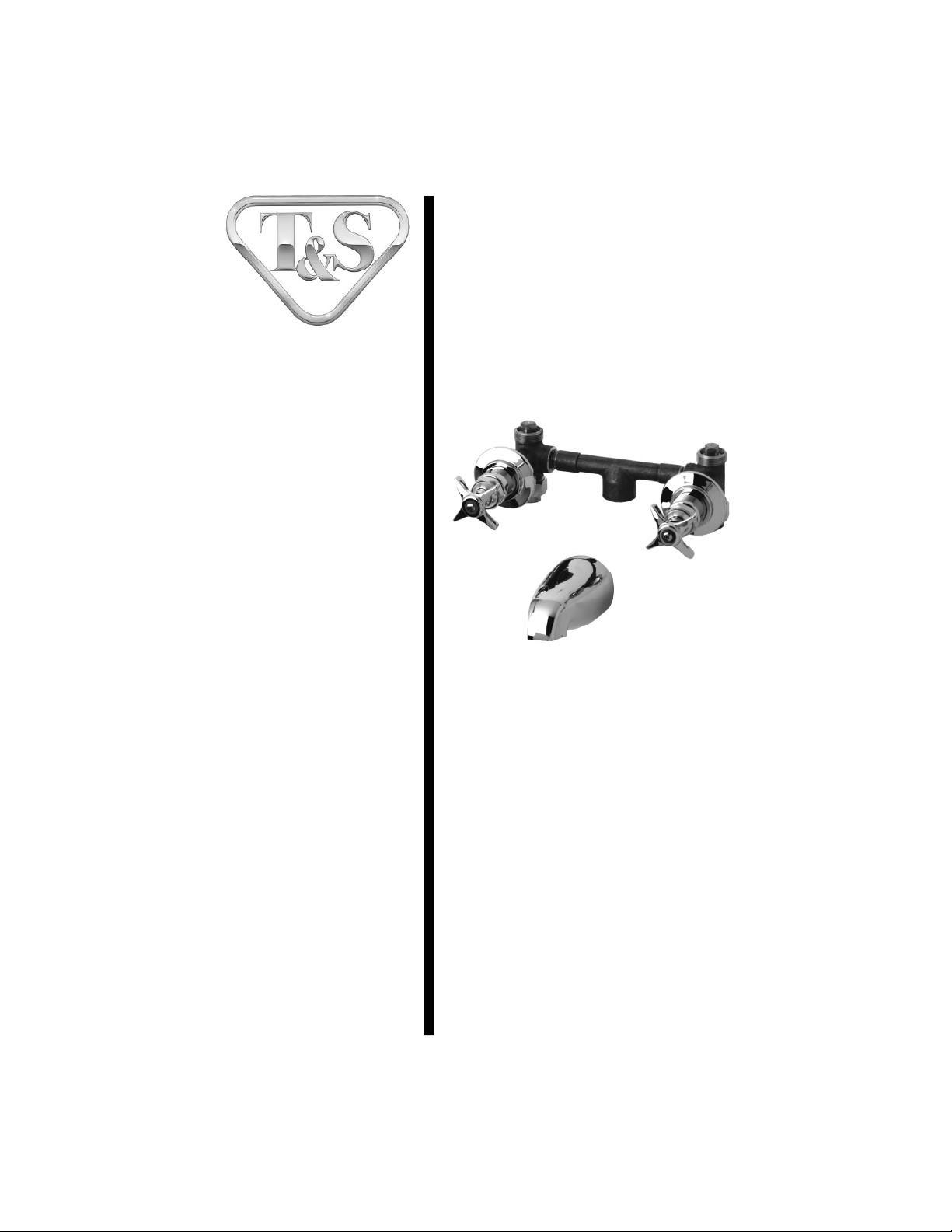
B-1070 Concealed
By-Pass Mixing Valve
Deutsch: Installations- und
Wartungsanleitungen
Español: la Instalación y las
Instrucciones de
Mantenimiento
Français: les Instructions
d’Installation et
d’Entretien
Page 2

7
1
10
Exploded View
9
8
6
5
4
3
2
11
12
13
* Some items are listed for instructional purposes
and may not be sold as separate parts.
Page 3

Part Number Guide
Mixing Valve Assembly
1 Asm, Concealed By-Pass Mixing Valve B-1030
Body, Valve *
2 Chamber Mix, 8" *
3 Set Screw, Escutcheon Flange *
4 Escutcheon *
5 Escutcheon Tube *
6 Asm, Spindle Eterna - Hot 005960-40
7 Handle, 4-Arm Kitchen 002521-45
8 Index Button, Blue - Cold 001660-45
Index Button, Red - Hot 001661-45
9 Screw, Lever Handle 000922-45
10 Nut, Flange Coupling *
11 Union, 1/2 Female *
12 Plug, Solid 1/2" Square Head *
13 Spout, 1/2 NLT Bathtub *
Page 4

General Instructions
Installation:
1. Shut off water supply and drain
lines. Drill (2) two holes, approximately 1-3/8” [34 cm] diameter in wall
with 8” [20 cm] center to center.
8” [20 cm]
1/2”
NPT
supply
line
10
1
3/4” IPS
supply
line to
tub
10
1/2”
NPT
supply
line
Note: The unit is also available with
6” [15 cm] center to center inlets.
2. After unpacking unit, remove
cartridge assembly from no.1.
(Loosen and remove no.3 at base of
no.4, slide no.4 off no.1.)
cartridge
assembly
4
5
3
1
10
3. Remove no.10 from no.1 and
attach to roughed-in piping (1/2” Iron
Pipe Size female inlets) using Teflon
Tape or pipe joint compound.
4. Attach no.1 onto no.10 and supply
pipes; tighten with a wrench.
5. Replace no.5, then no.4 and make
sure no.4 is flush against wall.
6. Replace no.6, attach no.7, no.8 and
no.9.
4
wall
3/4” IPS
supply
line to
tub
13
5
6
3
7.Attach no.13 to outlet pipe using
Teflon Tape or pipe joint compound.
Make sure no.13 is flush against wall.
8. Turn on water and check for leaks.
Page 5

Instrucciones
Generales
Instalación:
1. Cierre la fuente de agua y desagüe
las tuberias. Perfore (2) dos huecos,
aproximadamente de 1-3/8” [34 cm] de
díametro en la pared con distancia de
8” [20 cm] de centro a centro.
8” [20 cm]
Nota: Esta unidad también esta
disponible con entradas de 6” [15
cm] de centro a centro.
2. Después de desempacar la unidad,
remuéva el ensamble de cartucho de la
parte No.1. (Afloje y remuéva la parte
No.3 a la base de la parte No.4,
deslice la parte No.4 de la parte No.1.
ensamble
de cartucho
4
5
1
1
10
1/2” NPT
tubería de
surtido
1/2” NPT
tubería de
surtido
10
3/4” IPS
tubería de
surtido a la
bañera
4. Junte la parte No.1 a la parte No.10
y a la tubería de surtido; aprete con
una llave.
5. Coloque de nuevo la parte No.5,
luego la parte No.4 y asegúrese que la
parte No.4 este a rás con la pared.
6. Coloque de nuevo la parte No.6,
junte la partes No.7, No.8 y No.9.
4
5
6
pared
3
10
3. Remuéva la parte No.10 de la parte
No.1 y júntelo a la tubería aproximada
(1/2” Tamaño De Tubería De Hierro
entradas femeninas) usando cintas de
Teflon ó compuesto de coyuntura.
3
3/4” IPS
13
tubería de
surtido a
la bañera
7. Junte la parte No.13 al tubo de
desagüe usando cinta de Teflon ó
compuesto de coyuntura. Asegúrese
que la parte No.13 este a rás con la
pared.
8. Abra el agua e inspeccione por
filtraciones.
Page 6

Instructions
Générales
Installation:
1. Fermer la réserve de l’eau et
égoutter la tuyauterie. Percer deux (2)
trous avec un diamètre environ 34 cm.
avec 20cm. de centre à centre.
10
1
10
8” [20 cm]
Noter: L’élément être disponible
aussi avec les arrivées 15cm. centre
à centre.
2. Après vous vider l’élément de la
bôite , enlever l’assemblage de la
cartouche de Nº.1. (Desserrer et
enlever Nº.3 à la base de Nº.4, faire
glisser Nº.4 de Nº.1).
l’assemblage de
la cartouche
4
5
3
1
10
1/2”tuyau
qui fournir
l’eau NPT
3/4” tuyau
qui fournir
l’eau à la
baignoire
1/2”tuyau
qui fournir
l’eau NPT
4. Attacher Nº. 1 sur Nº.10 et les
tuyaux qui fournir l’eau, resserrer avec
une clef.
5. Remplacer Nº.5 puis Nº.4 et soyez
certain que Nº.4 être au même niveau
que le mur.
6. Remplacer Nº.6, attacher Nº.7, Nº.8
et Nº.9.
4
le mur
3/4” tuyau
qui fournir
l’eau à la
baignoire
13
5
6
3
3. Enlever Nº.10 de Nº.1 et attacher à
la tuyauterie (des arrivées f éminines
des tuyaux en fer 1/2”)
en utilisant le ruban en Téflon ou le
composé pour les tuyaux.
7.Attacher Nº.13 à la sortie en
utilisant le ruban en Téflon ou le
composé pour les tuyaux. Soyez
certain que Nº.13 être au même
niveau que le mur.
8. Recommencer l’eau et v érifier s’il y
a des fuites.
Page 7

Allgemeine
Anleitungen
Installation:
1. Wasserzulauf absperren und
Leitungen entleeren. Zwei ungefähr
3,4 cm große Löcher mit einem
Mittenabstand von 20cm in die Wand
bohren.
8” [20 cm]
Anmerkung: Die Einheit ist auch
mit einem Mittenabstand der
Zuleitungen von 15 cm erhältlich.
2. Nach Auspacken der Einheit
Patronengarnitur Nr. 1 entfernen.
(Nr. 3 von Nr. 4 unten lösen und
entfernen, Nr. 4 von Nr. 1
herunterschieben).
1
10
1,25 cm
NPT-
Zuflußrohr
1,25 cm
NPT-
Zuflußrohr
10
1,75 cm IPSZuflußrohr
zur Wanne
4. Nr. 1 mit Nr. 10 und den
Zuflußrohren verbinden; mit
Schraubenschlüssel festziehen.
5. Nr. 5 ersetzen und Nr. 4 ersetzen
und dann sicherstellen, daß Nr. 4 glatt
an der Wand anliegt.
6. Nr. 6 ersetzen, Nr. 7, Nr. 8 und Nr. 9
befestigen.
4
5
6
wand
Patronengarnitur
4
5
3
1
10
3. Nr. 10 von Nr. 1 entfernen und mit
innen aufgerauhtem Rohr (1,25 cm
Eisenrohr mit Innengewinde) unter
Verwendung von Teflonband oder
Rohrdichtungsmasse verbinden.
3
1,75 cm IPS-
13
Zuflußleitung
zur Wanne
7.Nr. 13 mit dem Ausflußrohr unter
Verwendung von Teflonband und
Rohrdichtungsmasse verbinden.
Sicherstellen, daß Nr. 13 glatt an der
Wand anliegt.
8. Wasserzulauf andrehen und auf
Dichtigkeit prüfen.
Page 8

RELATED T&S BRASS PRODUCT LINE
B-1030
Concealed By-
Pass Mixing
Valve
B-1065
Combination
Bath and
Shower Fitting
T&S BRASS AND BRONZE WORKS, INC.
A firm commitment to application-engineered plumbing products
2 Saddleback Cove, P.O. Box 1088, T & S Brass-Europe
Travelers Rest, SC 29690 ‘De Veenhoeve’
Phone: (864) 834-4102 Oude Nieuwveenseweg 84
Fax: (864) 834-3518 2441 CW Nieuwveen
E-mail: tsbrass@tsbrass.com The Netherlands
 Loading...