

Page 1
Limited One Year Warranty
T&S warrants to the original purchaser (other than
for purposes of resale) that such product is free from
defects in material and workmanship for a period of
one (1) year from the date of purchase. During this
one-year warranty period, if the product is found to
be defective, T&S shall, at its options, repair and/
or replace it. To obtain warranty service, products
must be returned to...
T&S Brass and Bronze Works, Inc.
Attn: Warranty Repair Department
2 Saddleback Cove
Travelers Rest, SC 29690
Shipping, freight, insurance, and other transportation charges of the product to T&S and the return
of repaired or replaced product to the purchaser are
the responsibility of the purchaser. Repair and/or
replacement shall be made within a reasonable time
after receipt by T&S of the returned product. This
warranty does not cover Items which have received
secondary finishing or have been altered or modified after purchase, or for defects caused by physical abuse to or misuse of the product, or shipment
of the products.
Any express warranty not provided herein, and
any remedy for Breach of Contract which might arise,
is hereby excluded and disclaimed. Any implied
warranties of merchantability or fitness for a particular purpose are limited to one year in duration. Under
no circumstances shall T&S be liable for loss of
use or any special consequential costs, expenses
or damages.
Some states do not allow limitations on how long
and implied warranty lasts or the exclusion or limitation of incidental or consequential damages, so
the above limitations or exclusions may not apply
to you. Specific rights under this warranty and other
rights vary from state to state.
Installation and
Maintenance
Instructions
B-0963 (1/2”)
CONTINUOUS PRESSURE
VACUUM BREAKERS
Deutsch: Installations- und
Wartungsanleitungen
Español: la Instalación y las
Instrucciones de
Mantenimiento
P/N: 098-009579-45 Rev.1
Date: 980521
Drawn: CW
Checked: MAB 7-23-98
Approved: MVW 7-23-98
Français: les Instructions
d’Installation et
d’Entretien
Page 2
3
26542
7
8
9
10
11
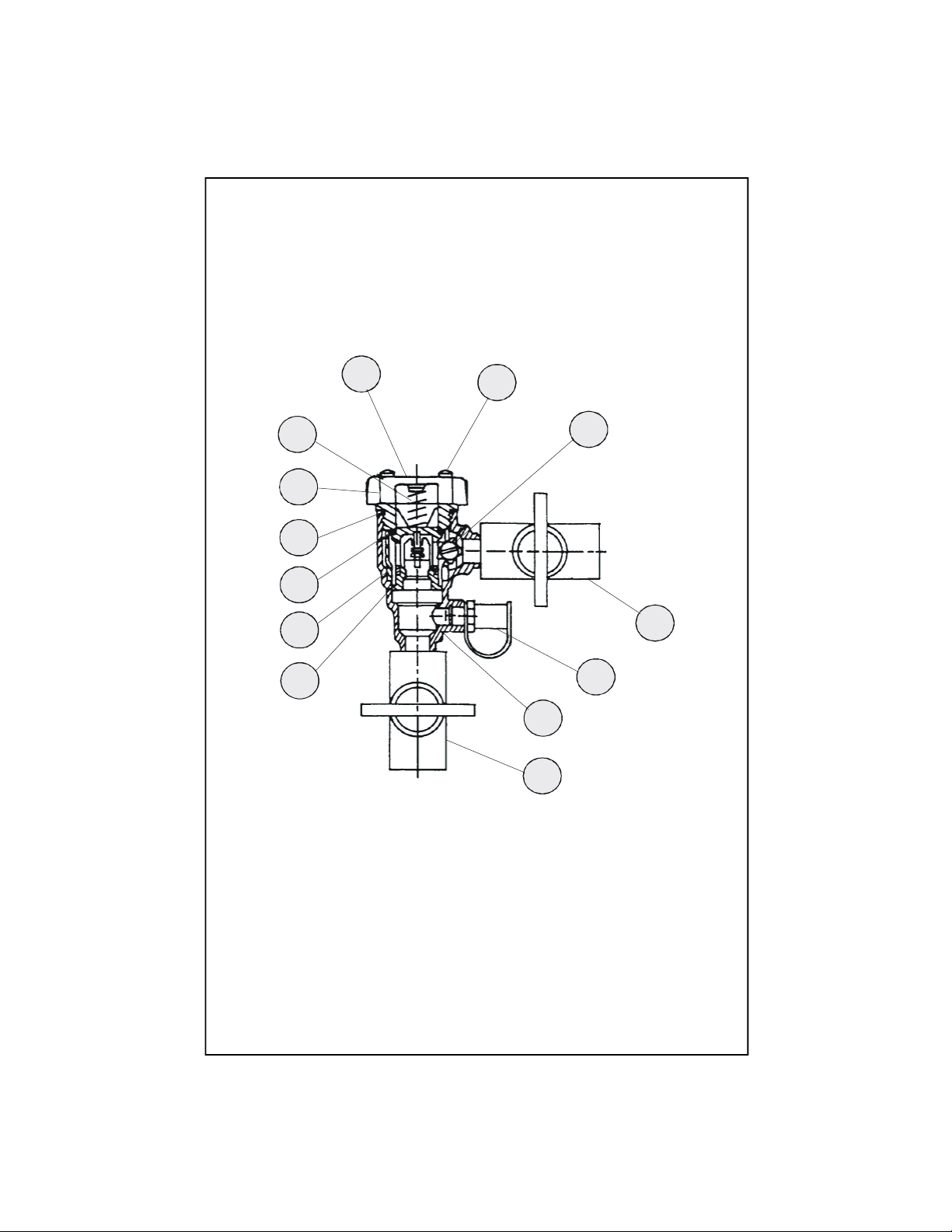
Sectional View
12
1
Page 3
Part Number Guide
Vacuum Breaker Assembly
1 Body
2 Shut-off Valve
3 Test Cock
4 Bleed Screw
5 Hood Screw
6 Hood
7 Vent Springs
8 Bonnet
9 O'-Ring
10 Vent 'O'-Ring
11 Retainer
12 Welded Check Assembly
Parts for this assembly are not available for replacement.
Page 4

General Instructions
Typical Installation:
Vacuum Breaker
1. Vacuum breakers designed for
continuous pressure applications
will follow the AVB guidelines of 6”
or the PVB guideline of 12” above
the flood rim. A typical installation is
shown below:
backplate
B-0963
vacuum
breaker
B-1403
Hose
Reel
B-1436
Reel
Kleen
Unit
hose &
spray
The valve consists of a modular
check and float assembly made of
engineered thermoplastic and
housed in a bronze body. The valve
is constructed with a molded
diaphragm separating the air inlet
from the potable water supply to
prevent spillage. Some slight
spillage may occur when water
outlet is above vacuum breaker or
when water is shut off abruptly.
Features:
Designed for indoor point of use
applications to prevent backsiphonage of contaminated water into
the potable water supply. Separation
of the water supply from the air inlet
is accomplished by means of a
diaphragm seal. This protects against
spillage during start-up or operation.
* Modular cartridge for ease of service
* Vent uses an ‘O’-ring for reliable operations
* Bronze body for durability
* Compact space-saving design
* Standardly equipped with an ‘E-Z/TC’ Testcock
Specifications:
A vacuum breaker should be installed according to manufacturer’s
instructions.
B-0121
base
faucet
Materials:
Springs - Stainless Steel
Bonnet - Noryl
Vent Disc - Silicone Rubber
Disc Holder - Noryl
Check Disc - Silicone Rubber
Body - Bronze
Pressure Temperature Ratings:
Working Temperature - 33º-180ºF
Max. pressure - 150 psi
Min. Pressure - 8 psi
End Connections:
Female NPT (National Pipe Threads) Ball Valve Shut-off
Page 5

Instruccione
Generales
Instalación Típica:
Anti- Sifón
1. El diseño del Anti- Sifón para
aplicaciones de presión continua
seguirán las normas de AVB de 6”
[15cm] o las normas de PVB de 12”
[30cm] sobre el borde de represa. Una
instalación típica esta ilustrada abajo.
Espaldor
B-0963
AntiSifón
B-1403
Manguera
Reel
B-1436
Reel
Kleen
Unit
Manguera
y
Rocecidor
La válvula consiste de tenedor
modular y un ensamble con flote
hecho de termoplástico ingenerado
y almacenado en cartucho de
bronce. La válvula está construída
con un diafragma formado
separando la entrada de aire del
surtido de agua potable para
prevenir derrames. Algunos leves
derrames pueden ocurrir cuando la
boquilla este sobre el Anti- Sifón o
cuando el agua se cierre
bruscamente.
Facciones:
Es diseñado para ser usado en el
interior en aplicaciones para prevenir
que agua contaminada se sifone al
surtido de agua potable. Separación
del surtido de agua a la entrada de
aire es llevada a cabo por medio de un
sello de diafragma. Esto protege
contra derrames durante el principio
de operación.
* Cartucho modular para facilitar el
mantenimiento.
* Agüjero usa una argolla de caucho para
operaciones dependibles.
* Cartucho de bronce para durabilidad
* Diseño compacto para ahorrar espacio
* Equipo universal con “E-Z/TC” válvula de
prueba
B-0121
Canilla
Especificaciones:
Un Ani- Sifón debe ser instalado a
las instrucciones de factoría.
Materiales:
Resorte - Hierro inoxidable
Cubierta - Noryl
Disco Ventilado - Goma De Silicone
Sostenedor Del Disco - Noryl
Disco Detendor - Goma De Silicone
Cuerpo - Bronce
Determinación De Presión Y
Temperatura:
Temperatura Operable: 33º-180ºF
Presión Máxima - 150 psi
Presión Mínima - 8 psi
Connecciones De Extremo:
Rosca De Tubo Femenina - Detendor
Válvula De Bola
Page 6

Instructions
Générales
L’Installation Typique:
La Vanne-Caisse-Vide
1. Les vannes -caisse-vide ont conçu
pour des applications continues de
pression suivront les directives de
AVB de 6 “[15 cm] ou de la directive
de pvb de 12 “ [30 cm] au-dessus du
bord d’inondation. L’installation
typique est montrée ci-dessous:
La soupape se composent d’un document
en circulation modulaire fait de
thermoplastique machiné et logé dans un
corps en bronze. La soupape est construite
avec un diaphragme moulé séparant
l’entrée d’air de l’approvisionnement en
eau potable pour empêcher le
débordement. Du léger débordement peut
se produire quand la sortie de l’eau est
au-dessus de la vanne-caisse- vide ou
quand l’eau est coupée brusquement.
B-0963 la vanne-
la tôle en arrière
caisse-vide
B-1403
le Tuyau
Reel
B-1436
Reel
Kleen
Unit
le tuyau
et le jet
B-0121
le robinet de
la base
Les Spécifications:
Une vanne-caisse-vide devoir être
installer en suivant les instructiosn du
fabricant.
Les Caractéristiques:
Conçu pour le point d’intérieur
d’applications d’utilisation pour empêcher
en arrière le siphonage de l’eau souillée
dans l’approvisionnement en eau potable.
La séparation de l’approvision-nement en
eau de l’entrée d’air est accompli à l’aide
d’un joint de diaphragme. Ceci se protège
contre le débordement pendant la
cartouche de la mise en train operation.
* Modulaire pour la facilité du service
* L’orifice utiliser un’anneau d’ “o” pour la
fonctionnment fiable
* Un corps en bronze pour la solidité
* Un dessin compact et qui économiser
l’espace
* Équipé standard d’un flotteur pour des
essais “E-Z/TC”
Les Matériaux
Les ressorts - l’acier inoxydable
Le capot - la noryl
Le disque d’orifice - le caoutchouc de silicone
Le support de disque - la noryl
Contrôleur de disque - le caoutchouc de silicone
Le corps - bronze
Les estimations de la température de
pression
La température de fonctionnement -33-180 f
La pression maximum-150 psi
La pression minimum- 8 psi
Connexions d’extrémité:
Femelle NPT- L’interruption de la soupape de bal
Page 7

Allgemeine Anleitungen
Typische Installation:
Rückschlagventil
1. Rückschlagventile, die für stetige
Druckanwendungen ausgelegt sind,
entsprechen den AVB-Richtlinien mit
6” [15 cm] oder der PVB-Richtlinie mit
12” [30 cm] über dem Überlaufrand.
Unten wird eine typische Installation
gezeigt:
Abschlußplatte
B-0963
Rückschlagventil
B-1403
Schlauch
Reel
B-1436
Reel
Kleen
Unit
Schlauch und
Brauseeinrichtung
Das Ventil besteht aus einer modularen
Regel- und Schwimmergarnitur, die aus
Thermoplastik hergestellt ist und sich in
einem Gehäuse aus Bronze befindet. Das
Ventil besteht aus einer geformten
Membran, die die Luftzufuhr von der
Trinkwasserzufuhr trennt, um Überlaufen
zu vermeiden. Leichtes Überlaufen kann
vorkommen, wenn der Wasserauslauf über
dem Vakuumunterbrecher liegt oder das
Wasser plötzlich abgesperrt wird.
Merkmale
Es ist für die Innenbenutzung konstruiert,
um den Rücklauf von Schmutzwasser in die
Trinkwasser-versorgung zu verhindern. Die
Trennung des Wasserzuflusses von dem
Luftzufluß wird durch eine Membrandichtung erzielt. Diese verhütet
Überlaufen während der Inbetriebnahme
Benutzung oder während des normalen
Betriebs.
• Modulare Kartusche zur einfacheren
Benutzung
• Entlüftung durch einen O-Ring für
zuverlässigen Betrieb
• Bronzegehäuse für Dauerhaftigkeit
• Kompakte, raumsparende
Konstruktion Ausgerüstet mit einem
“E-Z/TC” Testhahn
B-0121
Grundhahn
Vorgaben:
Ein Vakuumunterbrecher muß
entsprechend den Anweisungen des
Herstellers installiert werden.
Material:
Federn - rostfreier Stahl
Haube - Noryl
Entlüftungsscheibe - Silikongummi
Scheibenhalter - Noryl
Kontrollscheibe - Silikongummi
Gehäuse - Bronze
Drucktemperaturbewertungen:
Arbeitstemperatur - 33º -180º F
Höchstdruck - 150 psi
Mindestdruck - 8 psi
Endverbindungen:
NPT-Innenkugelabsperrventil
Page 8

RELATED T&S BRASS PRODUCT LINE
B-0965
Atmospheric Vacuum
Breaker Assembly
with Exposed Outlet
B-0929
Atmospheric Back
Flow Preventer
B-0456
Atmospheric
Vacuum Breaker
Assembly
T&S BRASS AND BRONZE WORKS, INC.
A firm commitment to application-engineered plumbing products
2 Saddleback Cove, P.O. Box 1088, T & S Brass-Europe
Travelers Rest, SC 29690 ‘De Veenhoeve’
Phone: (864) 834-4102 Oude Nieuwveenseweg 84
Fax: (864) 834-3518 2441 CW Nieuwveen
E-mail: tsbrass@tsbrass.com The Netherlands
 Loading...