

Page 1
Limited One Year Warranty
T&S warrants to the original purchaser (other than
for purposes of resale) that such product is free from
defects in material and workmanship for a period of
one (1) year from the date of purchase. During this
one-year warranty period, if the product is found to
be defective, T&S shall, at its options, repair and/
or replace it. To obtain warranty service, products
must be returned to...
T&S Brass and Bronze Works, Inc.
Attn: Warranty Repair Department
2 Saddleback Cove
Travelers Rest, SC 29690
Shipping, freight, insurance, and other transportation charges of the product to T&S and the return
of repaired or replaced product to the purchaser are
the responsibility of the purchaser. Repair and/or
replacement shall be made within a reasonable time
after receipt by T&S of the returned product. This
warranty does not cover Items which have received
secondary finishing or have been altered or modified after purchase, or for defects caused by physical abuse to or misuse of the product, or shipment
of the products.
Any express warranty not provided herein, and
any remedy for Breach of Contract which might arise,
is hereby excluded and disclaimed. Any implied
warranties of merchantability or fitness for a particular purpose are limited to one year in duration. Under
no circumstances shall T&S be liable for loss of
use or any special consequential costs, expenses
or damages.
Some states do not allow limitations on how long
and implied warranty lasts or the exclusion or limitation of incidental or consequential damages, so
the above limitations or exclusions may not apply
to you. Specific rights under this warranty and other
rights vary from state to state.
P/N: 098-005910-45 Rev.2
Date: 980504
Drawn: CW
Checked: MAB 7-23-98
Approved: MVW 7-23-98
Installation and
Maintenance
Instructions
B-0695 Service Sink
Fittings with Concealed
By-Pass Mixing Valves
Deutsch: Installations- und
Wartungsanleitungen
Español: la Instalación y las
Instrucciones de
Mantenimiento
Français: les Instructions
d’Installation et
d’Entretien
Page 2
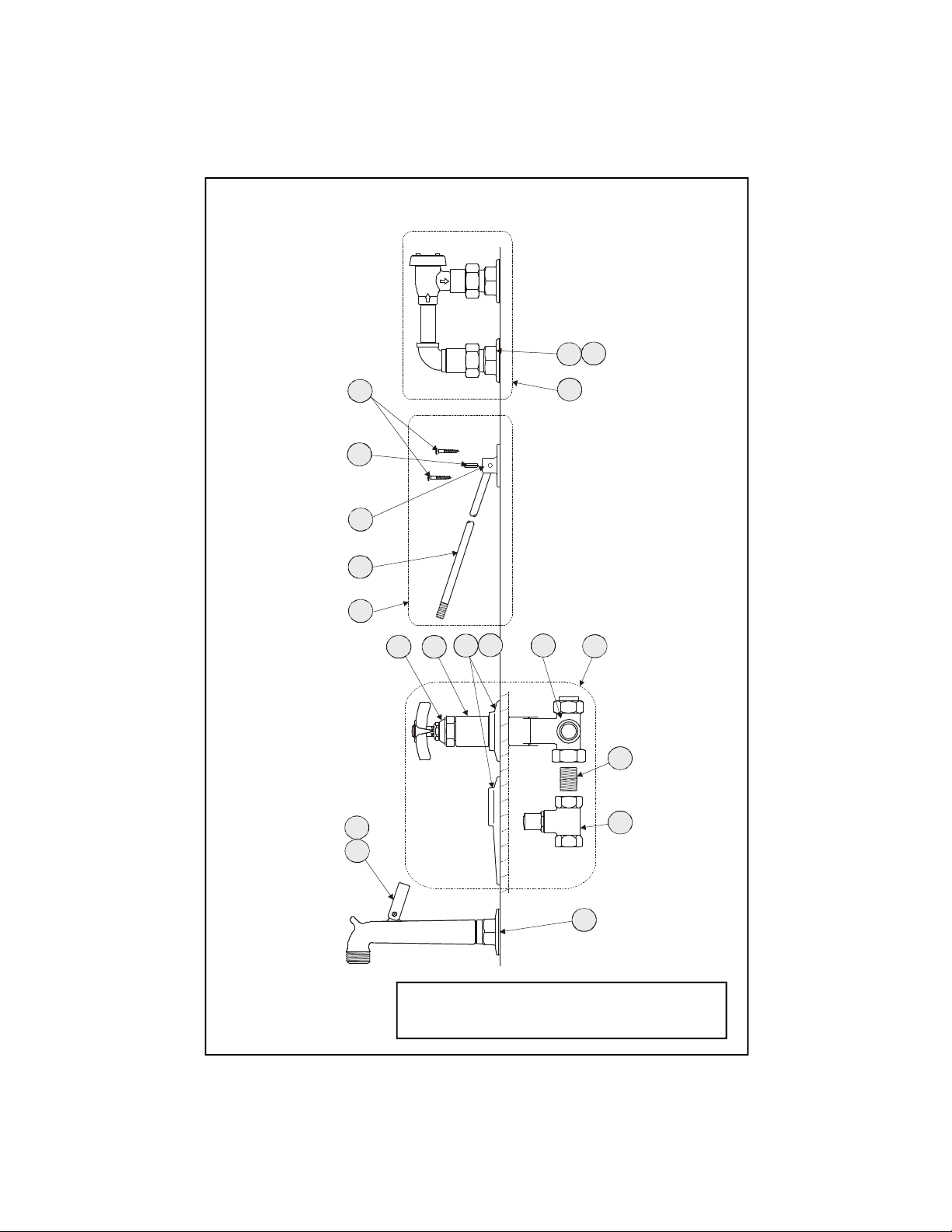
Exploded View
7112
15
1319181716
14
10
11
3
2
8
6
9
5
4
* Some items are listed for instructional purposes
and may not be sold as separate parts.
Page 3

Part Number Guide
Vacuum Breaker
1 Asm, Vacuum Breaker B-0929-A
2 Asm, Coupling Flange 002893-40
3 Washer, Coupling Nut 001019-45
Mixing Valve Assembly
4 Asm, By-Pass Mixing Valve B-1035
5 Body, Valve *
6 Asm, Spindle (Eterna) Hot 005960-40
7 Escutcheon Tube *
8 Escutcheon *
9 Set Screw, Escutcheon Flange *
10 Loose Key Stop 009745-45
11 Nipple, Close 1/2" *
Nozzle Assembly w/ Brace
19 Asm, Nozzle w/ Brace B-0671-POL
12 Flange 000013-40
13 Asm, Nozzle *
14 Asm, Upper Nozzle Support 009546-40
15 Support Rod *
16 Flange, Support *
17 Roll Pin *
18 Screw, Wall Mount 000915-45
Page 4

General Instructions
Installation: (Vacuum Breaker)
1. Drill holes 3-3/4” center-to-center in
wall where you will be installing no.1.
Note: Please consult applicable
plumbing codes for proper installed
height of no.1 over outlet of no.13.
2. Remove no.3 from no.1, install no.3
onto piping.
1
3
wall
outlet
5. (For B-0695 ST and B-0696 ST
models, add no.10 by using no.11 to
join the couplings together.)
Make connections to no.4:
B-0695: 1/2” IPS (Iron Pipe Size) female
union inlets; 1/2” close nipples.
B-0696: 5/8” union inlets; must solder
copper piping to inlets.
B-0695 ST: use B-0416 stops; 1/2” NPT
(National Pipe Thread) piping.
B-0696 ST: installer must supply 5/8”
solder joint to 1/2” NPT (National Pipe
Thread) adapter in order to attach supply
lines to no.10.
Installation: Nozzle
inlet
2
3. Reattach no.1 to no.3, making sure
no.2 is in place and tighten with a
wrench.
Installation: (Faucet Body)
4. After unpacking no.4, remove no.6,
no.7, no.8 and no.9 from no.5.
(Loosen no.8 at base of no.9, slide
both off no.5.)
wall
11
5
inlet
10
9
6
Use no.10 and no.11 for B-0695 ST
8
7
9
8
and B-0696 ST models
6. Attach no.12, onto supply pipe;
screw no.15 into no.13 attachment.
15
13
12
supply
line
7. Mark holes on wall for attachment
of no.16; use provided no. 18 to
secure no.16 to wall.
8. Insert no.17 into hole of no.16.
18
16
17
15
9. Turn on water and check for leaks.
See flow diagram on page 8.
Page 5

Instrucciones
Generales
Instalación: (Anti-sifón)
1. Perfore huecos de 9.5cm de centro a
centro en la pared donde la parte No.1
será instalada.
Nota: Por favor consulte codigos
aplicables de plomería para la apropiada
altura de instalación de la parte No.1
sobre el surtido de la parte No.13.
2. Remueva la parte No.3 de la parte
No.1, instale la parte No.3 en la
tubería.
1
3
2
pared
Salida
Entrada
3. Reemplaze la parte No.1 a la parte
No.3, asegurandose que la parte No.2
esté en su sitido y aprete con una
llave.
Instalación: (Canilla)
4. Después de desempacar la parte
No.4, remueva las partes No.6, No.7 y
No.8 da la parte No.5. (Afloje la parte
No.8 a la base de la parte No.9, deslize
ambos de la parte No.5.)
pared
11
5
Entrada
10
9
6
Use las partes No.
10 y 11 para los
modelos B-0695
ST y B-0696 ST.
8
7
9
8
5. (Para modelos B-0695 ST y B-0696
ST, agrege la parte No.10 usando la
parte No.11 para unir los enganches.)
Para Hacer Conecciones a la parte No.4:
B-0695: 1/2” IPS (Tamaño de tubería de
hierro) entradas de uniones femeninas
tubo enrroscado corto de 1/2”.
B-0696: Uniones de entrada de 5/8” tiene
que soldar tubería de cobre a las entradas.
B-0695 ST: Use pares modelo B-0416;
tubería NPT (Rosca Nacional De Tubo).
B-0696 ST: El instalador debe de surtir la
coyuntura soldada de 5/8” al adaptador de
1/2” NPT (Rosca Nacional De Tubo) en
orden de unir las lineas de surtido a la
parte No.10.
Instalación: Boquilla
6. Junte la parte No.12 a la linea de
surtido; atornille la parte No.15
dentro del encaje de la parte No.13.
15
13
7. Para colocar la parte No.16 marque
los huecos en la pared; para mantener
la parte No.16 use la parte No.18 que
esta surtida.
8. Insarte la
parte No.17
dentro del
hueco de la
parte No.16.
9. Abra la fuente de agua e
inspeccione por filtraciones.
Vea el diagrama de
desagüe en la pagina 8.
12
Linea
de
Surtido
18
16
17
15
Page 6

Instructions
Générales
L’Installation: La VanneCaisse-Vide
1. Percer les trous 9.5cm de centre-àcentre où vous aller installer Nº.1.
Noter: Prier consulter les codes
plomberies applicables pour la
haulteur correcte de l’installation de
Nº.1 au-dessous-de la sortie de Nº.13.
2. Enlever Nº.3 de Nº.1, installer Nº.3
sur la tuyauterie.
3
le
mur
la
sortie
5. (Pour les modeles B-0695 et B-0696
ST, ajouter Nº.10 en utilisant Nº.11
pour joindre les raccords ensemble)
Faire les branchements à Nº.4:
B-0695: les arrivèes unions IPS (Iron Pipe
Size) de 1/2”; les raccords proches de 1/2”.
B-0696: les arrivèes unions de 5/8”; on
devoir souder les tuyaux cuivres aux
arrivèes.
B-0695 ST: utiliser les arrêts B-0416; le
tuyau NPT (National Pipe Thread) de 1/2”.
B-0696 ST: L’installeur devoir fournir le
joint de sordure de 5/8” à l’adapteur NPT
(National Pipe Thread) de 1/2” pour
attacher les tuyaux qui fournir l’eau à
Nº.10.1
L’Installation: De L’Ajutage
l’arrivèe
2
3. Réattacher Nº.1 à Nº.3, soyez
certain que Nº.2 être à sa place et
resserrer avec une clef.
L’Installation: Du Robinet
4. Après on vider la bôite, enlever
Nº.6, N.7, N.8 et Nº.9 de Nº.5.
(Desserrer Nº.8 à base de Nº.9, faire
glisser tous les deux de Nº.5.)
le mur
11
10
5
l’arrivèe
9
6
Utiliser Nº.10 et Nº.11 pour les modèles
8
7
9
8
B-0695 et B-0696 ST
6. Attacher Nº.12 sur le tuyau qui
fournir l’eau; visser Nº.15 dans
l’accessoire de Nº.13.
13
15
12
fournir
tuyau
7. Marquer les trous sur le mur pour
attacher Nº.16; utiliser le Nº.18 fourni
pour attacher Nº.16 au mur.
8. Insérer
Nº.17 dans
le trou de
Nº.16.
18
16
17
15
9. Recommencer l’eau et vérifier s’il
y a des fuites.
Voir le diagramme de la
circulation au page 8.
Page 7

Allgemeine
Anleitungen
Installation: Vakuumunterbrecher
1. Löcher, die von Mitte zu Mitte 9,5
cm entfernt sind, in die Wand bohren,
wo Nr. 1 installiert werden soll.
Anmerkung: Für die richtige Höhe von
Nr. 1 über dem Auslauf von Nr. 13 bitte
die zutreffenden Installateurvorschriften
nachsehen.
2. Nr. 3 von Nr. 1 entfernen, Nr. 3 auf
dem Rohrsystem installieren.
Wand
1
3
2
Ablauf
Einlauf
3. Nr. 1 wieder mit Nr. 3 verbinden.
Sicherstellen, daß Nr. 2 richtig
eingesetzt ist, und mit einem
Schraubenschlüssel festziehen.
Installation: (Armaturrumpf)
5. (Für die Modelle B-0695 ST und
B-0696 ST Nr. 10 hinzufügen und Nr.
11 verwenden, um die Kupplungen
miteinander zu verbinden.
Herstellung der Verbindung mit Nr. 4:
B-0695: Einlaufrohr mit 1/2” IPS FE
Innenverschraubung;1/2” Verschlußnippel.
B-0696: 5/8” Einlaufrohre; Kupferrohre
müssen mit Einlaufrohren verschweißt
werden.
B-0695 ST: B-0416 Stopfen benutzen;
Rohre Größe 1/2” NPT. (National Pipe
Thread)
B-0696 ST: Der Installateur muß das 5/8”
Verbindungstück mit dem 1/2”NPT.
(National Pipe Thread) Zwischenstück
verschweißen, um die Zulaufrohre mit Nr.
10 zu verbinden.
Schwenkhahninstallation
6. Nr. 12 mit dem Zulaufrohr verbinden;
Nr. 15 in Nr. 13 einschrauben.
15
13
12
4. Nach dem Auspacken von Nr. 4, Nr.
6, 7, 8 und 9 von Nr. 5 entfernen.
(Nr. 8 unten auf Nr. 9 lösen, beide von
Nr. 5 abziehen.
Wand
11
10
5
Einlauf
9
8
7
6
Nr.10 und Nr.11 für Modelle B-0695
ST und B-0696 ST benutzen.
9
8
7. Löcher an der
Wand für Teil 16
markieren;
mitgelieferte Nr. 18
benutzen, um Nr. 16
an der Wand zu
Zulaufrohr
18
16
17
befestigen.
8. Nr. 17 in das Loch
15
von Nr. 16 einfügen.
9. Wasserzufuhr andrehen und auf
Lecks prüfen.
Siehe Durchflußdiagram auf Seite 8.
Page 8

Flow diagram
B-0929A
Vacuum
Breaker
Upper Nozzle
Support
Spindle
Assembly
Escutcheon
Support Rod
Spout
Plumbing supplied
by others
Wall
Concealed
By-Pass
Mixing Valve
B-0416
Stop
Water
Supply
Inlet
T&S BRASS AND BRONZE WORKS, INC.
A firm commitment to application-engineered plumbing products
2 Saddleback Cove, P.O. Box 1088, T & S Brass-Europe
Travelers Rest, SC 29690 ‘De Veenhoeve’
Phone: (864) 834-4102 Oude Nieuwveenseweg 84
Fax: (864) 834-3518 2441 CW Nieuwveen
E-mail: tsbrass@tsbrass.com The Netherlands
 Loading...