

Page 1
Limited One Year Warranty
T&S warrants to the original purchaser (other than
for purposes of resale) that such product is free from
defects in material and workmanship for a period of
one (1) year from the date of purchase. During this
one-year warranty period, if the product is found to
be defective, T&S shall, at its options, repair and/
or replace it. To obtain warranty service, products
must be returned to...
T&S Brass and Bronze Works, Inc.
Attn: Warranty Repair Department
2 Saddleback Cove
Travelers Rest, SC 29690
Shipping, freight, insurance, and other transportation charges of the product to T&S and the return
of repaired or replaced product to the purchaser are
the responsibility of the purchaser. Repair and/or
replacement shall be made within a reasonable time
after receipt by T&S of the returned product. This
warranty does not cover Items which have received
secondary finishing or have been altered or modified after purchase, or for defects caused by physical abuse to or misuse of the product, or shipment
of the products.
Any express warranty not provided herein, and
any remedy for Breach of Contract which might arise,
is hereby excluded and disclaimed. Any implied
warranties of merchantability or fitness for a particular purpose are limited to one year in duration. Under
no circumstances shall T&S be liable for loss of
use or any special consequential costs, expenses
or damages.
Some states do not allow limitations on how long
and implied warranty lasts or the exclusion or limitation of incidental or consequential damages, so
the above limitations or exclusions may not apply
to you. Specific rights under this warranty and other
rights vary from state to state.
P/N: 098-003117-45 Rev.1
Date: 980402
Drawn: CW
Checked: MW 6-10-98
Approved: MAB 6-10-98
Installation and
Maintenance
Instructions
Service Sink Faucet
B-0650 Series
Deutsch: Installations- und
Wartungsanleitungen
Español: la Instalación y las
Instrucciones de
Mantenimiento
Français: les Instructions
d’Installation et
d’Entretien
Page 2
5174
9
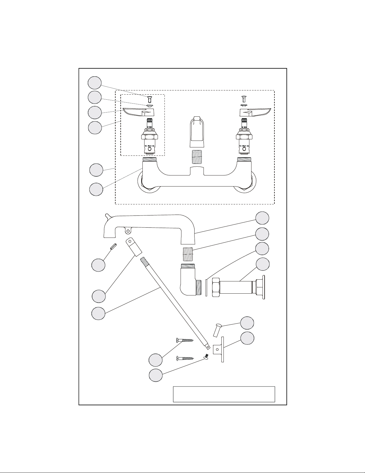
Some items are listed for instructional
purposes and may not be sold as separate parts.
2
8
7
6
1
10
Exploded View
Front View
apply
loctite #680
3
11
12
Side View
15
16
13
14
*
Page 3

Part Number Guide
Faucet Body Assemblies
1 Asm, Base Faucet B-0650POL
2 Body, Faucet *
3 Asm, Inlet Extension B-0441
4 Washer, Coupling Flange 001019-45
5 Nipple, Close 1/2 HWL 002534-25
6 Asm, Eterna LH Spindle 002713-40
Asm, Eterna RH Spindle 002714-40
7 Handle, Lever (Cold) 001636-45
Handle, Lever (Hot) 001637-45
8 Index, Button (Red - Hot) 001661-45
Index, Button (Blue - Cold) 001660-45
9 Screw, Handle 000922-45
10 Pin, Coiled 3/16" x 5/8 s.s. 001311-45
11 Clevis 000639-25
12 Support Rod 000447-40
13 Screw, Wall Mount 000915-45
14 Screw, Handle 003199-45
15 Nut, Handle 003198-45
16 Flange 003007-40
17 Spout 000185-40
Page 4

General Instructions
Nozzle Installation:
17
16
Note: Nozzles should be installed first.
Remove no.6 from both sides of faucet.
1. Apply Loctite #680 to threads of no.5.
17
5
2. Thread no.5 into no.17, then rotate
no.17 into no.1 until tight with no.17
facing front of sink.
Faucet Installation:
1
3. Shut off water supply and drain lines. Drill (2) two 7/8” holes in wall or
backsplash of sink with 8” centers, where you are installing no.1.
4
3
4. Remove no.3
from back of no.1.
(No.3 is 1/2”
11
eccentric female)
5. Apply teflon tape or pipe
joint compound to threads of
water supply lines.
6. Attach no.3 to water
12
13
15
backsplash
or wall
water
supply line
supply lines and tighten by
hand. (Attach no.1 to no.3,
adjusting center to center fit
by turning no.3 if needed.)
Tighten with a wrench.
14
6
7. Screw no.12 into no.11 on bottom side of no.17. Attach no.12 to no.16 by
placing no.15 through no.16 and no.12 then screwing no.14 into no.15 and
tightening.
8. Drill (4) four 3/16” hole into wall or backsplash where no.12 and no.16 rest
against wall. Secure no.16 by screwing no.13 thru no.16 and into wall or backsplash.
9. Turn on water supply and check for leaks.
Page 5

Instrucciones
Generales
Instalación:
17
16
Nota: Las boquillas deben ser instaladas
primero. Remueva la parte No.6 de ambos
lados de la canilla.
1. Aplique Loctite No. 680 a la rosca de la
parte No.5.
2. Enrosque la parte No.5 entre la parte No.17,
luego gire la parte No.17 entre la parte No.1 hasta que este apretada, con la
parte No.17 orientada hacia el frente de el lavatorio.
17
5
1
Instalación De La Canilla:
3. Cierre la fuente principal de agua y desagüe las tuberias. Perfore (2) dos
huecos de 2cm de diámetro en la pared o en el espaldar del lavatorio con centros
de 20cm, donde la parte No.1 será instalada.
4
3
4. Remuéva la parte No.3
de la parte posterior de la
parte No.1 (No.3 es
rosca femenina de
1.25cm excéntrica)
5. Aplique cinta para rosca de
tubería o compuesto de coyuntura
a las lineas del surtido de agua.
6. Junte la parte No.3 a las lineas del
surtido de agua y aprete a mano.
(Junte la parte No.1 a la
No.3,ajustando la medida de centro a
centro girando la parte No.3 si es
necesario.) Aprete con una llave.
11
12
13
14
15
Espaldar ó
Pared
Lineas de
surtido
6
7. Atornille la parte No.12 entre la No.11 en el lado de abajo de la parte No.17.
Junte la parte No.12 a la parte No.16 colocando la parte No.15 a través de las
partes No.16 y No.12 luego atornillando la parte No.14 en la No.15 y apretela.
8. Perfore (4) cuatro huecos de .5cm en la pared o el aspaldar donde las partes
No.12 y 16 hagan contacto. Asegure la parte No.16 atornillando la parte No.13 a
través de la parte No.16 dentro de la pared o el espaldar.
9. Abra la fuente de agua e inspeccione por filtraciones.
Page 6

Instructions
Générales
L’Installation De L’Ajutage:
17
16
Noter: Les ajutages devoir être installer au
début. Enlever Nº.6 de chaque côté du
robinet.
1. Appliquer “loctite #680” aux filets de Nº.5.
2. Mettre Nº.5 à traves N.17, puis tourner
N.17 dans N.1 jusqu ‘il être bien serre avec
N.17 vers la face de l’évier.
17
5
6
L’Installation Du Robinet:
3. Fermer la réserve de l’eau et égoutter la tuyauterie. Percer (2) deux trous 2cm,
avec un diamètre de 3cm dans le mur ou le garde-boue de l’évier avec les centres
de 20cm, où vous aller installer Nº.1.
4. Enlever Nº.3 de la
partie arrière de Nº.1.
(Nº.3 être 1.5cm
femelle excentrique).
5. Appliquer le ruban en
Téflon ou le composé pour les
tuyaux aux filets des tuyaux qui
fournir l’eau.
6. Attacher Nº.3 aux tuyaux qui
fournir l’eau et resserrer par le
main. (Attacher Nº.1 à Nº.3 en
réglant centre à centre en
tounant Nº.3 si nécessaire).
Resserrer avec une clef.
11
12
13
14
15
1
4
le garde-boue
ou le mur
3
le tuyau qui
fournir l’eau
7. Visser Nº.12 dans Nº.11 sur le côté arrière de Nº.17. Attacher Nº.12 à Nº.16 en
placent Nº.15 à travers Nº.16 et Nº.12. Puis visser Nº.14 dans Nº.15 et resserrer.
8. Percer (4) quatre trous 9cm dans le mur ou le garde-boue de l’évier où Nº.12 et
Nº.16 rester contre le mur. Attacher Nº.16 en vissant Nº.13 à travers Nº.16 dans
le mur ou le garde-boue.
9. Recommencer l’eau et vérifier s’il y a des fuites.
Page 7

Allgemeine
Anleitungen
Schwenkhahninstallation:
17
16
Anmerkung: Die Schwenkhähne sind als erstes
zu installieren. Nr.6 von beiden Seiten des
Schwenkhahns entfernen.
1. Loctite Nr. 680 auf das Gewinde von Nr.5
auftragen.
2. Nr.5 durch Nr.17 führen, dann Nr.17 in Nr.1
drehen, bis Nr.17 festsitzt, wobei Nr.17 auf die
Vorderseite des Spültisches auszurichten ist
17
5
6
1
Armatureninstallation:
3. Wasserzufuhr abstellen und Leitungen entleeren. Zwei (2) 2,25cm große Löcher
mit einem Durchmesser von ungefähr 3cm in die Wand oder den Spritzschutz
bohren mit einer Mitte von 20cm, in die Nr.1 installiert wird.
4
4. Nr.3 von der
Rückseite von 1 entfernen
(Nr.3 ist das 1,25cm
große Exzenterventil).
5. Teflonband oder
Rohrdichtmasse auf das Gewinde
der Wasserzufuhrleitungen
auftragen.
6. Nr.2 mit der Wasserzufuhr
verbinden und mit der Hand anziehen.
(Nr.1 mit Nr.3 verbingen, die beiden
Mittelpunkte aufeinander ausrichten,
indem Nr.3, falls erforderlich, gedreht
wird.) Mit einem Schraubenschlüssel
festdrehen.
7. Auf der Unterseite von 17 Nr.12 in Nr.11 einschrauben. Nr.12 auf Nr.16
anbringen, indem Nr.15 durch Nr.16 und Nr.12 gesteckt wird und dann Nr.14 in
Nr.15 eingeschraubt und festgezogen wird.
11
12
15
13
14
3
Spritzschultz
oder Wand
Wasserversorgungsleitungsrohr
8. Wo Nr.12 und Nr.16 auf der Wand aufliegen, vier (4) 0,5cm Löcher in die Wand
oder den Spritzschutz bohren. Nr.16 befestigen, indem Nr.13 durch Nr.16 in die
Wand oder den Spritzschutz geschraubt wird.
9. Wasserzufuhr andrehen und auf Lecks prüfen.
Page 8

RELATED T&S BRASS PRODUCT LINE
B-0657
Service Sink Faucet
B-0669
Service Snk Faucet
T&S BRASS AND BRONZE WORKS, INC.
A firm commitment to application-engineered plumbing products
2 Saddleback Cove, P.O. Box 1088, T & S Brass-Europe
Travelers Rest, SC 29690 ‘De Veenhoeve’
Phone: (864) 834-4102 Oude Nieuwveenseweg 84
Fax: (864) 834-3518 2441 CW Nieuwveen
E-mail: tsbrass@tsbrass.com The Netherlands
 Loading...