

Page 1
Limited One Year Warranty
T&S warrants to the original purchaser (other
than for purposes of resale) that such product is
free from defects in material and workmanship
for a period of one (1) year from the date of purchase. During this one-year warranty period, if
the product is found to be defective, T&S shall,
at its options, repair and/or replace it. To obtain
warranty service, products must be returned to...
T&S Brass and Bronze Works, Inc.
Attn: Warranty Repair Department
2 Saddleback Cove
Travelers Rest, SC 29690
Shipping, freight, insurance, and other transportation charges of the product to T&S and the
return of repaired or replaced product to the
purchaser are the responsibility of the purchaser.
Repair and/or replacement shall be made within
a reasonable time after receipt by T&S of the
returned product. This warranty does not cover
Items which have received secondary finishing
or have been altered or modified after purchase,
or for defects caused by physical abuse to or
misuse of the product, or shipment of the products.
Any express warranty not provided herein,
and any remedy for Breach of Contract which
might arise, is hereby excluded and disclaimed.
Any implied warranties of merchantability or fitness for a particular purpose are limited to one
year in duration. Under no circumstances shall
T&S be liable for loss of use or any special consequential costs, expenses or damages.
Some states do not allow limitations on how
long and implied warranty lasts or the exclusion
or limitation of incidental or consequential damages, so the above limitations or exclusions may
not apply to you. Specific rights under this warranty and other rights vary from state to state.
P/N: 098-003112-45 Rev.4
Date: 980827
Drawn: CW
Checked: MAB 10-16-98
Approved: MW 10-15-98
Installation and
Maintenance
Instructions
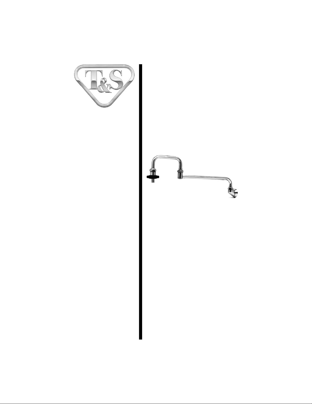
Range Faucet
(B-0580 and B-0585)
Deutsch: Installations- und
Wartungsanleitungen
Español: la Instalación y las
Instrucciones de
Mantenimiento
Français: les Instructions
d’Installation et
d’Entretien
Page 2
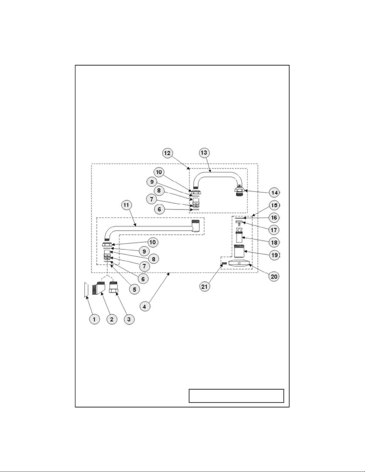
Exploded View
* Some items are listed for instructional
purposes and may not be sold as separate parts.
Page 3

Part Number Guide
Range Faucet Assemblies
1 Flange (B-0580 Wall Mounted) 000101-40
2 Body (B-0580 Nozzle) 000181-40
3 Swivel Piece (B-0585 Nozzle) 000590-25
4 Asm, Double Jointed Nozzle 002848-40
5 Asm, Nozzle 12" Back Spout 002871-40
6 "O"-Ring 001074-45
7 Sleeve, Swivel 011429-45
8 Swivel Piece *
9 Washer, Swivel 009538-45
10 Nut, Swivel *
11 Nozzle, 12" Plated *
12 Asm, Nozzle 6" Front Spout 002870-40
13 Nozzle, 6" Plated *
14 Cap *
15 Asm, Outlet 005948-40
16 "O"-Ring, Bonnet 001061-45
17 Seat Washer 001089-45
18 Spout 001498-25
19 Body, Spout 000587-25
20 Handle 001126-20
21 Set Screw, Handle 000936-45
Page 4

General Instructions
Nozzle Installation:
1. Shut off water supply and drain
lines. Existing supply lines should be
roughed into wall or sink backsplash. Use 1/2” IPS (Iron Pipe Size)
inlets (male for B-0580, female for
B-0585) supplied by others.
2. Loosen no.10 on assembly.
Remove no.4 assembly from no.2 or
no.3.
4
12
10
3
2
1
wall or
back-splash
3. Tighten no.1 towards no.2 as far as
it will go by hand.
4. Apply teflon tape to threads of inlet
pipe. Screw no.2 (B-0580) into inlet
pipe as far as it will go, tighten with a
wrench.
5. Tighten no.1 so that it is flush
against wall.
6. Replace no.4 assembly into no.2
(B-0580) or no.3 (B-0585), tighten
no.10 firmly against no.2 or no.3.
Model B-0585
For swivel repair or replacement of
(o-ring) no.6 and (sleeves) no.7:
1. Shut off water supply and drain
lines.
2. Loosen no.10 on assembly. Remove
no.4 assembly from no.2 or no.3.
3. Insert one no.7 onto no.8. Install
no.6 on no.8 and lubricate liberally
with o-ring grease. Install second
no.7 onto no.8. (See Enlarged View)
8
7
6
Outlet Assembly:
For repair or replacement of parts:
1. Insert prongs of no.17 through
hole in part no.18 and flair outward,
as shown:
prongs
17
18
19
21
2. Slide no.18 through no.19 and
no.19 through no.20.
17
20
3. Insert no.21 into no.20 and tighten
firmly and securely against no.19.
Page 5

Instrucciones Generales
Instalación De La Boquilla:
1. Cierre el surtido de agua y desague
las tuberias. Las lineas existentes de
surtido, deben de ser aproximadas en
la pared o en el espaldar de la sentina.
Use entradas de 1/2” IPS (Tamaño De
Tubería De Hierro) (masculina para
B-0580, femenina para B-0585) surtido
por otros.
2. Afloje la parte No.10 del ensamble.
Remuéva el ensamble No.4 de la parte
No.2 ó No.3.
4
12
10
3
2
1
Pared o
espaldar
3. Aprete a mano la parte No.1 hacia la
parte No.2 hasta su máximo trayecto.
4. Aplique cinta de Teflon a las roscas
del tubo de entrada. Atornille la parte
No.2 (B-0580) dentro del tubo de
entrada a su máximo trayecto, aprete
con una llave.
5. Aprete la parte No.1 a medida que
este a rás contra la pared.
6. Coloque de nuevo el ensamble
No.4 entre la parte No.2 (B-0580) ó la
parte No.3 (B-0585), firmemente
aprete la parte No.10 contra la parte
No.2 ó No.3.
Modelo B-0585
Para el reparo ó el reemplazo de la
(argolla de goma) parte No.6 y
(manga) parte No.7:
1. Cierre el surtido de agua y desagüe
las tuberias.
2. Afloje la parte No.10 en el ensamble.
Remuéva el ensamble No.4 de la parte
No.2 ó No.3.
3. Insarte una parte No.7 en la parte
No.8. Instale la parte No.6 en la parte
No.8 y lubrique liberalmente con grasa
para argolla
de goma.
Instale la
segunda
parte No.7
8
7
6
en la parte No.8.
(Vea el diagrama ampliado).
Ensamble De Desagüe:
Para el reparo o reemplazo de
partes:
1. Insarte la puas de la parte No.17 a
través del hueco en la parte No.18 y
doblelas hacia fuera, como esta
demostrado.
17
18
19
21
2. Deslice la parte No.18 a través de la
parte No.19 y la parte No.19 a través
de la parte No.20.
3. Insarte la parte No.21 entre la parte
No.20 y firme y seguramente aprete
contra la parte No.19.
puas
17
20
Page 6

Instructions
Générales
L’Installation De L’Ajutage:
1. Fermer la réserve de l’eau et
égoutter la tuyauterie. Les tuyaux qui
fournir l’eau devoir être déja dans le
mur ou le garde-boue de l’évier.
Utiliser les arrivées IPS(en Anglais
“Iron pipe size- en Français “la taille
des tuyaux en fer”) 1/2” fournir par les
autres.
2. Desserrer Nº.10 sur l’assemblage.
Enlever l’assemblage Nº.4 de Nº.2 ou
Nº.3.
4
10
12
Pour la réparation de l’ajutage
pivotant ou le remplacement de
(l’anneau “o”) Nº.6 (des manches)
Nº.7:
1. Fermer la réserve de l’eau et
égoutter la tuyauterie.
2. Desserrer Nº.10 sur l’assemblage.
Enlever l’assemblage Nº.4 de Nº.2 ou
Nº.3.
3. Insérer un Nº.7 dans Nº.8. Installer
Nº.6 sur Nº.8 et lubrifier
généreusement
avec la
graisse.
Installer
le deuxième
Nº.7 sur Nº.8.
(Voir la vue agrandie).
8
7
6
3
2
1
le mur ou le
garde-boue
3. Resserrer Nº.1 vers Nº.2 aussi loin
que possible par le main.
4. Appliquer le ruban en Téflon aux
filets des tuyaux d’arrivée. Visser Nº.2
(B-0580) dans le tuyau d’arrivée aussi
loin que possible, resserrer avec une
clef anglaise.
5. Resserrer Nº.1 jusqu’il être au même
niveau que le mur.
6. Remplacer l’assemblage Nº.4 dans
Nº.2 (B-0580) ou Nº.3 (B-0585),
resserrer Nº.10 feremement contre
Nº. 2 ou Nº. 3.
Modèle B-0585
L’Assemblage De La Sortie:
Pour la réparation et le remplacement des parties
1. Insérer les dents de Nº. 17 à travers
le trou dans la partie de Nº.18 et le
mettre comme indiqué:
17
18
19
21
2. Faire glisser Nº.18 à travers Nº.19 et
Nº.19 à travers Nº.20
3. Insérer Nº.21 dans Nº.20 et resserer
bien et fermement contre Nº.19.
les dents
17
20
Page 7

Allgemeine Anleitungen
Schwenkarm-Installation:
1. Wasserzulauf absperren und
Leitungen entleeren. Die bestehenden
Zuflußleitungen sollten aufgerauht
und in die Wand oder den Spritzschutz
eingeführt werden. IPS-Zuflußrohre
mit 1,25 cm Durchmesser von
Drittlieferanten benutzen (mit
Außengewinde für B-0580, mit
Innengewinde für B-0585).
2. Nr. 10 der Garnitur lockern. Nr. 4 der
Garnitur von Nr. 2 oder Nr. 3
entfernen.
4
12
10
3
2
1
Wand oder
Spritzschutz
3. Nr. 1 in Richtung Nr. 2 so weit wie
möglich mit der Hand festdrehen.
4. Nr. 1 in Richtung Nr. 2 so weit wie
möglich mit der Hand festdrehen.
Modell B-0585
Für Kuglerersatz oder Ersatz von Nr.
6 (Dichtungsring) oder Nr. 7 (Muffe):
1. Wasserzulauf absperren und
Leitungen entleeren.
2. Nr. 10 der Garnitur lockern. Nr. 4 der
Garnitur von Nr. 2 oder Nr. 3
entfernen.
3. Eine Nr. 7 in Nr. 8 einfügen. Nr. 6 auf
Nr. 8 installieren und reichlich mit
Dichtungsringfett schmieren. Zweite
Nr. 7 auf Nr. 8 installieren (siehe
vergrößerte Abbildung).
8
7
6
Abflußgarnitur:
For repair or replacement of parts:
1. Kontaktstifte von Nr. 17 durch das
Loch von Teil Nr. 18 geben und wie
gezeigt nach außen biegen:
Kontaktstifte
17
18
17
5. Nr. 1 festdrehen, so daß sie glatt an
die Wand anliegt.
6. Garnitur Nr. 4 in Nr. 2 (B-0580) oder
Nr. 3 (B-0585) ersetzen, Nr. 10 fest
gegen Nr. 2 oder Nr. 3 anziehen.
19
21
20
2. Nr. 18 durch Nr. 19 und Nr. 19
durch Nr. 20 hindurchführen.
3. Nr. 21 in Nr. 20 einfügen und fest
und sicher gegen Nr. 19 anziehen.
Page 8

RELATED T&S BRASS PRODUCT LINE
B-0575
Range Fuacet
B-0592
Pot and Kettle
Filling Faucet
T&S BRASS AND BRONZE WORKS, INC.
A firm commitment to application-engineered plumbing products
2 Saddleback Cove, P.O. Box 1088, T & S Brass-Europe
Travelers Rest, SC 29690 ‘De Veenhoeve’
Phone: (864) 834-4102 Oude Nieuwveenseweg 84
Fax: (864) 834-3518 2441 CW Nieuwveen
E-mail: tsbrass@tsbrass.com The Netherlands
 Loading...