

Page 1
Limited One Year Warranty
T&S warrants to the original purchaser (other
than for purposes of resale) that such product
is free from defects in material and workmanship for a period of one (1) year from the date
of purchase. During this one-year warranty
period, if the product is found to be defective,
T&S shall, at its options, repair and/or replace
it. To obtain warranty service, products must
be returned to…
T&S Brass and Bronze Works, Inc.
Attn: Warranty Repair Department
2 Saddleback Cove
Travelers Rest, SC 29690
Shipping, freight, insurance, and other
transportation charges of the product to T&S
and the return of repaired or replaced product
to the purchaser are the responsibility of the
purchaser. Repair and/or replacement shall be
made within a reasonable time after receipt by
T&S of the returned product. This warranty does
not cover Items which have received secondary
fi nishing or have been altered or modifi ed after
purchase, or for defects caused by physical
abuse to or misuse of the product, or shipment
of the products.
Any express warranty not provided herein,
and any remedy for Breach of Contract which
might arise, is hereby excluded and disclaimed.
Any implied warranties of merchantability or
fi tness for a particular purpose are limited to
one year in duration. Under no circumstances
shall T&S be liable for loss of use or any special
consequential costs, expenses or damages.
Some states do not allow limitations on
how long and implied warranty lasts or the
exclusion or limitation of incidental or consequential damages, so the above limitations or
exclusions may not apply to you. Specifi c rights
under this warranty and other rights vary from
state to state.
Installation and
Maintenance
Instructions
FLOOR MOUNTED
SINGLE PEDAL VALVE
B-0507
Deutsch: Installations- und
Wartungsanleitungen
Español: la Instalación y las In-
strucciones de Mantenimiento
P/N: 098-012361-45 Rev.2
Date: 09-07-04
Drawn: TEH
Checked: MVW 09-08-04
Approved: MVW 09-08-04
Français: les Instructions
d’Installation et
d’Entretien
Page 2
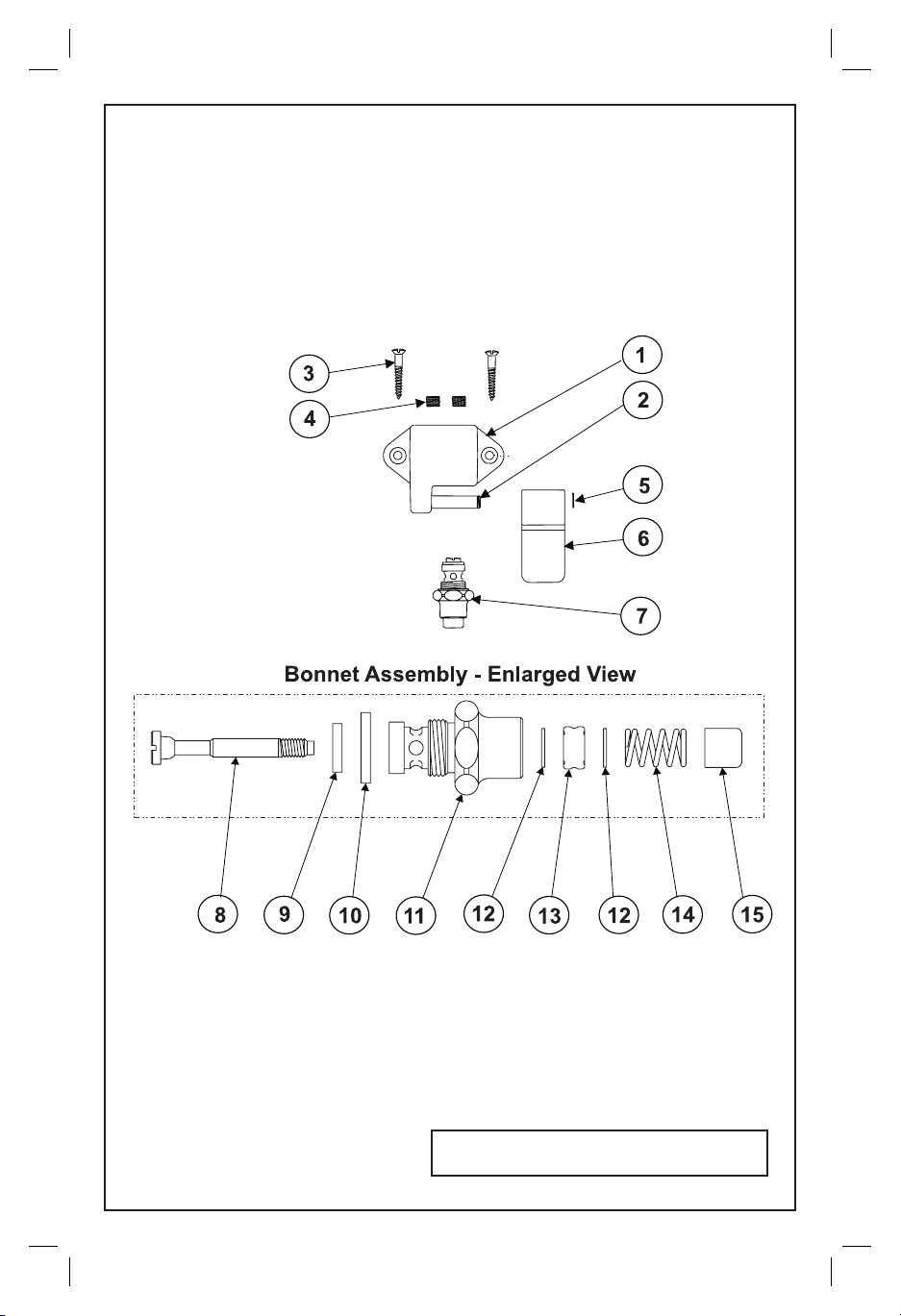
Exploded View
* Some items are listed for instructional
purposes and may not be sold as separate parts.
2
Page 3

Part Number Guide
Body & Shaft Assembly
1
Body, Single Pedal
2
Shaft
3
Screw, Mounting
4
Socket Plug
5
Snap-Ring
6
Pedal, Foot (Blank)
7
Asm, Bonnet
Bonnet Assembly - 005312-40
8
Stem, Vavle
9
Seat Washer
10
Washer, Bonnet Binding
11
Bonnet
12
Washer
13
Packing Stem
14
Spring
15
Pushbutton
*
*
000915-45
*
012512-45
000090-25
005312-40
009306-20
012915-45
*
000608-25
000974-45
001100-45
003690-45
000753-25
3
Page 4

General Instructions
Installation:
1. Shut off water supply and drain lines.
2. Drill (two) holes for ½” NPT (National Pipe Threads) inlets and (one) ½”
NPT outlets for connections coming from wall. (See drilling dimensions for
hole.)
1/2” NPT Outlet
1-15/16
1”
fl oor
3/4”
C/C
1/2” NPT Inlet
3. Mount assembly to fl oor with two no.3’s, allowing 4” [10 cm] or more
from back of unit to wall. Install two (2) inlets (hot and cold sides) and one
(1) outlet.
4. Apply tefl on tape or pipe joint compound to threads of supply lines. Con-
nect supply lines with ½” NPT piping.
5. Turn on water and check for leaks.
Note: It is strongly recommended that each supply line be equipped with a
hammer arrester installed per manufacturer’s instructions. A typical installation is shown:
insert
no.3
4”
[10 cm]
wall
out
in
Note: Piping and
hammer arrester supplied by others.
fl oor
Note: To order replacement parts, order the B-50-P parts
kit. (For repair of no.7)
4
hammer arrester
Page 5

Instrucciones Generales
Instalación:
1. Cierre la fuente de agua y desagüe las tuberías.
2. Perfore 2 (dos) huecos para entradas de 1/2” NPT (Rosca Nacional Para
Tubería) y 1 (uno) para salida 1/2” NPT para conexiones viniendo de la
pared. ( Refi érase a las dimensiones de taladrar para el hueco.)
1/2” NPT Salida
1-15/16
1”
Piso
3/4”
C/C
1/2” NPT Entrada
3. Monte el ensamble al piso con dos partes No.3, permitiendo 4” [10 cm] o
más desde la parte de atrás de la unidad hasta la pared. Instale dos (2) entradas (lados caliente y frío) y una (1) salida.
4. Aplique cinta de Tefl on o compuesto de coyuntura alas roscas de la línea
de surtido. Conecte las líneas de surtido con tubería de rosca de ½” NPT.
5. Abra el agua e inspeccione por fi ltraciones.
Nota: Es altamente recomendado que cada línea de surtido sea equipada con
amortiguador de vibración. Una instalación típica esta demostrada:
Insarte la parte
No.3
[10 cm]
Pared
Fuera
en
Nota: Tuberia
y amortiguador
de vibración
surtido por
Piso
Amortiguador de vibración
Nota: Ordene el estuche de reparos B-50-P, para repuestos. (Para reparar la parte No.7)
5
Page 6

Instructions Générales
L’Installation:
1. Fermer la réserve de l’eau et égoutter la tuyauterie.
2. Percer (2) deux trous pour une arrivée de ½” NPT et une sortie de ½”
NPT pour les branchements qui venir du mur. (Voir les dessins pour percer
pour le trou.)
1/2” NPT la sortie
1-15/16
1”
le plancher
3. Attacher l’assemblage au plancher avec deux Nº.3’s, laisser10 cm ou plus
de l’arrière de l’élément au mur. Installer deux (2) arrivées (les côtés chauds
et froids les côtés chauds et froids ) et une (1) sortie.
4. Appliquer le ruban en Téfl on ou le composé pour les tuyaux aux tuyaux
qui fournir l’eau avec la tuyauterie NPT.
5. Recommencer l’eau et vérifi er s’il y a des fuites.
Noter: On lui recommande vivement que chaque canalisation d’alimentation
devrait être équipée d’un “arrête-vibrations”. Une installation typique est
montrée.
insérer
Nº.3
4”
[10 cm]
3/4”
C/C
le mur
hors de
dans
1/2” NPT l’arrivées
Noter: La tuyauterie et
“l’arrête-vibrations” est
fourir par les autres.
le plancher
Noter: Pour commander les parties remplacements’ commander la trousse à outils B-50. (Pour réparer Nº.7)
un’“arrête-vibrations”
6
Page 7

Allgemeine Anleitungen
Installation:
1. Wasserzufuhr abstellen und Rohre leerlaufen lassen.
2. Bohren Sie zwei 1/2 Zoll große Löcher für NPT (Nationale Rohr Gewinde)
Einlässe und ein 1.3 cm großes Loch für NPT Rohrauslauf für die Verbindungen zur
Wand.(für Bohrmaße und Anordnung, siehe Zeichnung unten.)
1/2” NPT Auslauf
1-15/16
Boden
1”
3/4”
C/C
1/2” NPT Einlaß
3. Montieren Sie die Einheit am Boden mit Hilfe von zwei Nr. 3, wobei mindestens
10 cm zwischen der Rückseite der Einheit und der Wand verbleiben müssen. Installieren Sie zwei (2) Zuläufe (heiß und kalt) und einen (1) Ablauf.
4. Tefl onband oder Rohrkitt zum Gewinde der Zufuhrleitungen auftragen. Verbinden
Sie die Zufuhrleitungen mit 1/2 Zoll NPT Rohren.
5. Wasser andrehen und auf Dichtheit prüfen.
Achtung: Es empfi ehlt sich in jeder Wasserleitung einen Rückschlag Arrettierer
einzubauen. Typisch erfolt der Einbau wie abgebildet:
Anmerkung: Rohre und
Rückschlag Arrettierer
Einsatz Nr. 3
4”
[10 cm]
Wand
Abfl uss
Zufuhr
nicht über unsere Firma
erhältlich.
Boden
Hinweis: Falls Ersatzteile zur Reparatur benötigt werden,
bestellen Sie das B-50-P Ersatzteilkit. (Zur Reparatur der Nr.
7
Rückschlag Arrettierer
Page 8

RELATED T&S BRASS PRODUCT LINE
B-0504
DOUBLE PEDAL VALVE,
WALL MOUNTED
T&S BRASS AND BRONZE WORKS, INC.
A fi rm commitment to application-engineered plumbing products
2 Saddleback Cove, P.O. Box 1088, T & S Brass-Europe
Travelers Rest, SC 29690 ‘De Veenhoeve’
Phone: (864) 834-4102 Oude Nieuwveenseweg 84
Fax: (864) 834-3518 2441 CW Nieuwveen
E-mail:
tsbrass@tsbrass.com The Netherlands
8
 Loading...