

Page 1
Limited One Year Warranty
T&S warrants to the original purchaser (other than
for purposes of resale) that such product is free from
defects in material and workmanship for a period of
one (1) year from the date of purchase. During this
one-year warranty period, if the product is found to
be defective, T&S shall, at its options, repair and/
or replace it. To obtain warranty service, products
must be returned to...
T&S Brass and Bronze Works, Inc.
Attn: Warranty Repair Department
2 Saddleback Cove
Travelers Rest, SC 29690
Shipping, freight, insurance, and other transportation charges of the product to T&S and the return
of repaired or replaced product to the purchaser are
the responsibility of the purchaser. Repair and/or
replacement shall be made within a reasonable time
after receipt by T&S of the returned product. This
warranty does not cover Items which have received
secondary finishing or have been altered or modified after purchase, or for defects caused by physical abuse to or misuse of the product, or shipment
of the products.
Any express warranty not provided herein, and
any remedy for Breach of Contract which might arise,
is hereby excluded and disclaimed. Any implied
warranties of merchantability or fitness for a particular purpose are limited to one year in duration. Under
no circumstances shall T&S be liable for loss of
use or any special consequential costs, expenses
or damages.
Some states do not allow limitations on how long
and implied warranty lasts or the exclusion or limitation of incidental or consequential damages, so
the above limitations or exclusions may not apply
to you. Specific rights under this warranty and other
rights vary from state to state.
Installation and
Maintenance
Instructions
ATMOSPHERIC
VACUUM BREAKERS
B-0969 (1/2”)
(Also use for replacement parts,
B-0969-RK01, 1/2”)
Deutsch: Installations- und
Wartungsanleitungen
P/N: 098-013216-45 Rev.0
Date: 04-16-01
Drawn: TEH
Checked: DLT 04-20-01
Approved: MVW 06-27-01
Español: la Instalación y las
Instrucciones de
Mantenimiento
Français: les Instructions
d’Installation et
d’Entretien
Page 2
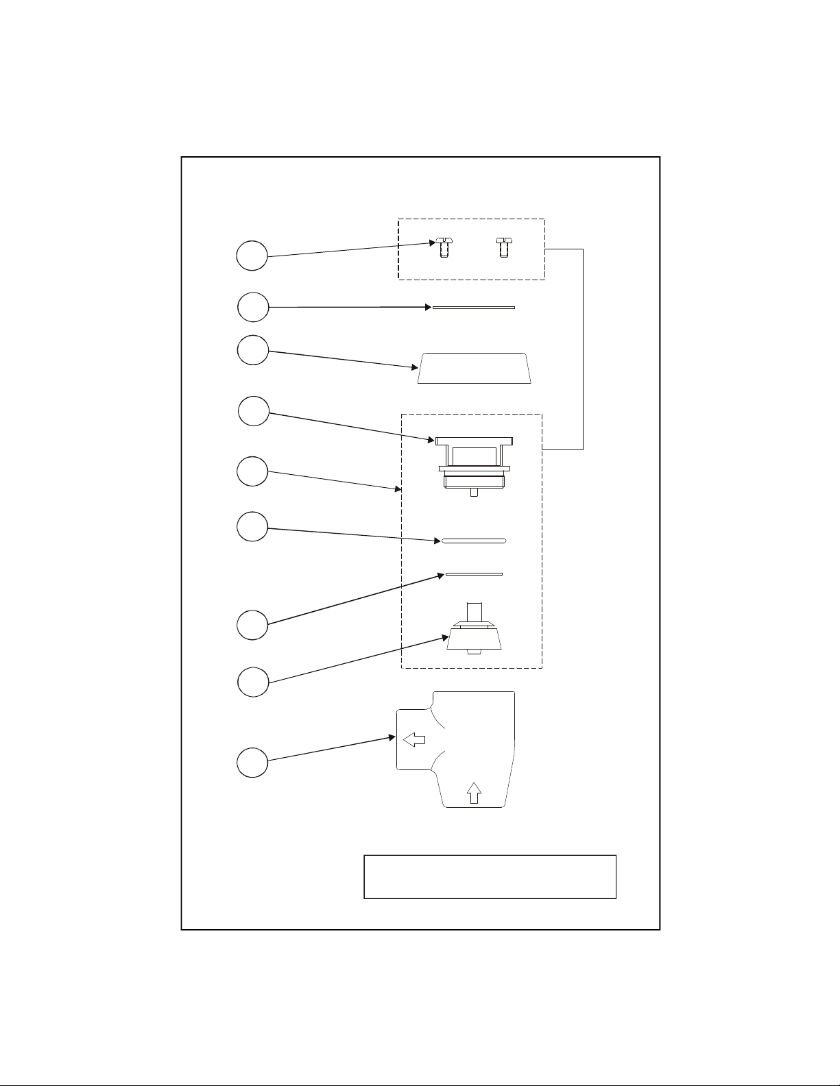
Exploded View
Some items are listed for instructional
5
2
3
6
4
7
8
9
1
*
purposes and may not be sold as separate parts.
2
Page 3

Part Number Guide
Vacuum Breaker Assemblies & Kit
1 Body, Vacuum Breaker, 1/2" *
2 Namplate *
3 Coverplate *
4 Repair Kit, Vacuum Breaker, 1/2" B-0969-RK01
5 Screws *
6 Insert *
7 Sealing Disk *
8 O-Ring, Plunger *
9 Piston *
3
Page 4

General Instructions
Typical Installation:
Single Vacuum Breaker
1. Vacuum breaker must be installed
with the supply connected to the
bottom and the outlet connected to
the appliance, as shown below:
1
not less than
6” (CIL)
supply
valve
2. The bottom of the no.1 should be
at least 6” above the flood rim of the
fixture or appliance.
3. When using a portable appliance,
no.1 should be installed at least 6”
above the highest point to which the
outlet can be raised, as shown:
overflow
or flood
rim
fixture or
appliance
Note: Where the device is a
separate unit, in the absence of a
Critical Installation Level (CIL)
mark, the extreme bottom of the
no.1 casting should be used to
determine its installed position.
Where the device is incorporated
in an outlet tube furnished by the
manufacturer, the extreme bottom
of the internal unit should be
noted on the outside of the tube by
a CIL line, for use in determining
its installed position.
4. The water supply valve must be
installed on the supply side (ahead)
of the vacuum breaker, and no shutoff valve should be installed on the
outlet side (downstream).
5. The vacuum breaker should not be
subjected to continuous pressure for
more than twelve (12) hours.
Note: This device should not be
installed in a concealed or
inaccessible location, nor where
the venting water from the device
during its normal functioning
may be deemed objectionable.
1
supply
valve
highest position of appliance
not less than 6” (CIL)
4
Page 5

General Instructions
Typical Installation:
Follow the instructions in the Single
Vacuum Breaker section, Step 1 thru
step 5.
B-0969-RK01 (Kit)
1/2” Vac. Breaker
6
Two typical T&S unit installations
will look as follows:
B-929 Atmospheric Vacuum
Breaker Assembly
B-657
Service Sink
Faucet
Repair Kit:
1. For replacement parts, reorder
complete unit, or replace internal
parts with a repair kit: B-969-RK01
½” Vacuum Breaker.
install here
7
8
install here
9
5. Reassemble in reverse order.
Note: Make sure surface
inside the body is clean,
and then tighten no.6 until
it is firmly seated against
the inside shoulder of no.1.
2. (See exploded view on sheet 2.)
Remove the two no.5 from top of
no.3, and lift off no.2 and no.3.
3. Unscrew and remove no.6, no.7,
no.8 and no.9 from inside no.1.
4. Replace parts with new parts from
kit.
5
Page 6

RELATED T&S BRASS PRODUCT LINE
B-0965
Atmospheric Vacuum
Breaker Assembly
with Exposed Outlet
B-0929
Atmospheric Back
Flow Preventer
B-0456
Atmospheric
Vacuum Breaker
Assembly
T&S BRASS AND BRONZE WORKS, INC.
A firm commitment to application-engineered plumbing products
2 Saddleback Cove, P.O. Box 1088, T & S Brass-Europe
Travelers Rest, SC 29690 ‘De Veenhoeve’
Phone: (864) 834-4102 Oude Nieuwveenseweg 84
Fax: (864) 834-3518 2441 CW Nieuwveen
E-mail: tsbrass@tsbrass.com The Netherlands
 Loading...