

Page 1

Limited One Year Warranty
T&S warrants to the original purchaser (other
than for purposes of resale) that such product is
free from defects in material and workmanship
for a period of one (1) year from the date of purchase. During this one-year warranty period, if
the product is found to be defective, T&S shall,
at its options, repair and/or replace it. To obtain
warranty service, products must be returned to...
T&S Brass and Bronze Works, Inc.
Attn: Warranty Repair Department
2 Saddleback Cove
Travelers Rest, SC 29690
Shipping, freight, insurance, and other transportation charges of the product to T&S and the
return of repaired or replaced product to the
purchaser are the responsibility of the purchaser.
Repair and/or replacement shall be made within
a reasonable time after receipt by T&S of the
returned product. This warranty does not cover
Items which have received secondary finishing
or have been altered or modified after purchase,
or for defects caused by physical abuse to or
misuse of the product, or shipment of the products.
Any express warranty not provided herein,
and any remedy for Breach of Contract which
might arise, is hereby excluded and disclaimed.
Any implied warranties of merchantability or fitness for a particular purpose are limited to one
year in duration. Under no circumstances shall
T&S be liable for loss of use or any special consequential costs, expenses or damages.
Some states do not allow limitations on how
long and implied warranty lasts or the exclusion
or limitation of incidental or consequential damages, so the above limitations or exclusions may
not apply to you. Specific rights under this warranty and other rights vary from state to state.
P/N: 098-012427-45
Date: 990609
Drawn: CW
Checked: MAB 8-10-99
Approved: MVW 8-6-99
Installation and
Maintenance
Instructions
Mixing Faucet
B-0315
(B-0315-LN shown)
Deutsch: Installations- und
Wartungsanleitungen
Español: la Instalación y las
Instrucciones de
Mantenimiento
Français: les Instructions
d’Installation et
d’Entretien
Page 2
Side View
Front View
6
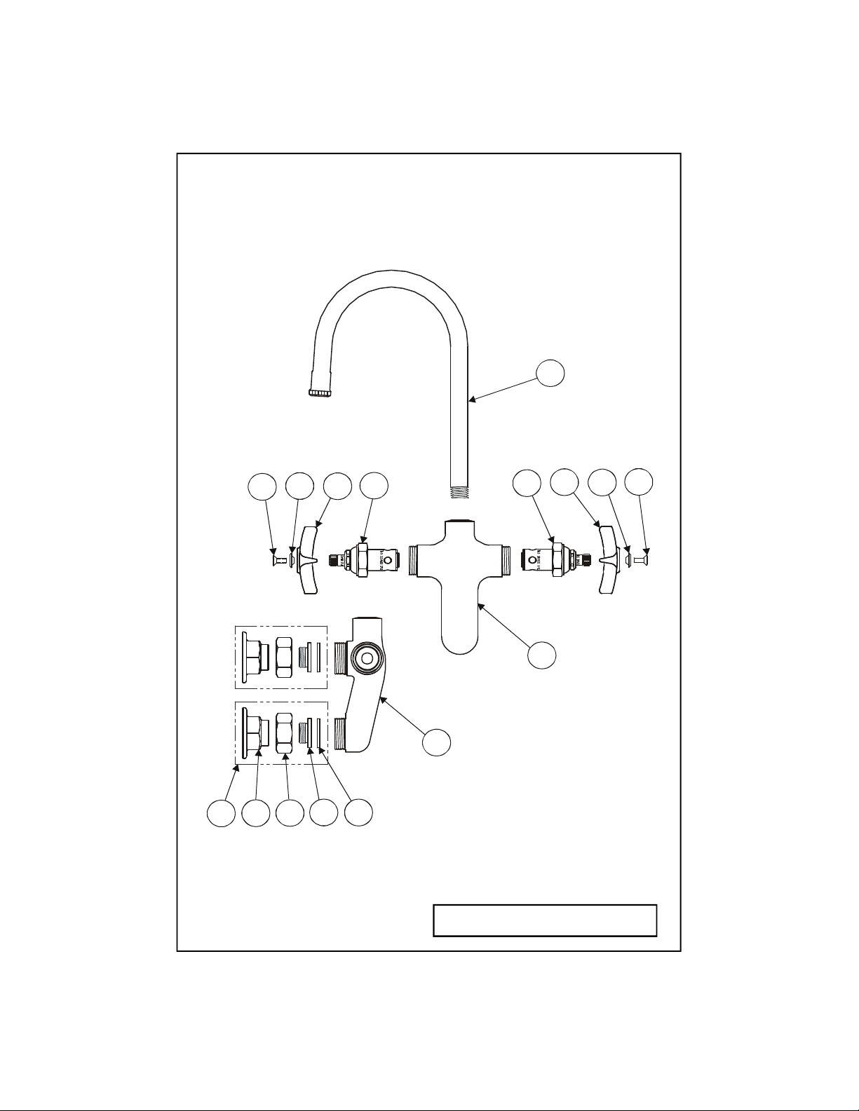
Exploded View
2
3
5
2
12
3
6
4
1
1
9
10
8
7
11
* Some items are listed for instructional
purposes and may not be sold as separate parts.
2
Page 3

Part Number Guide
Faucet Assemblies
1 Body, Wash Sink *
2 Asm, Spindle, Eterna 005960-40
3 Handle, 4 Arm Kitchen 002521-45
4 Button, Index Handle, Blue- Cold 001660-45
5 Button, Index Handle, Red- Hot 001661-45
6 Screw, Lever Handle 000922-45
7 Asm, Coupling Flange 1/2 002893-40
8 Flange, 1/2 NPT *
9 Nut, Flange Coupling *
10 Insert, Flange *
11 Washer, Coupling Nut 001019-45
12 Asm, Gooseneck w/ Tip 120X
3
Page 4

General Instructions
Nozzle Installation:
Note: Nozzles should be installed
first.
1. Shut off water supply and drain
lines. Apply Teflon tape or pipe joint
compound to threaded end of no.12.
2. Tighten no.12 firmly by hand into
no.1.
12
apply Teflon
tape to
threads
before
installing
no.1
2. Apply Teflon tape or pipe joint
compound to water supply lines.
3. Connect no.7 to water supply lines
by attaching no.8 with eccentric
centers onto nipple supplied by
others and tighten no.8 against wall.
Make sure no.11 is in place. Nut
behind wall to be supplied by others.
Trim supply lines if necessary.
11
8
wall
water supply line
(supplied by others)
nut
Faucet Installation:
1. Drill (2) two holes, approximately
1-1/4” [3 cm] diameter in wall with 3”
[7 cm] vertical centers, where you are
installing no.1.
3
[7 cm]
1
8
water supply line
(supplied by others)
4. Turn on water supply and check
for leaks.
4
Page 5

Instrucciones Generales
Instalación de la Boquilla:
Nota: Las boquillas deben de ser
instaladas primero.
1. Cierre la fuente de agua y desagüe
las tuberías. Aplique cinta de Teflon
o compuesto de coyuntura al extremo
con rosca de la parte No.12.
2. Firmemente apriete a mano la parte
No.12 entre la parte No.1.
12
Aplique
cinta de
Teflon a las
roscas antes
de instalar
la parte No.1
2. Aplique cinta de Teflon o
compuesto de coyuntura a las líneas
de agua.
3. Conecte la parte No.7 a las líneas
de surtido juntando la parte No.8 con
centros excéntricos al tubo surtido
por otros y apriete la parte No.8
contra la pared. Asegúrese que la
parte No.11 este en su sitio. La
tuerca detrás de la pared será
surtida por otros. Si es necesario
recorte las líneas de agua.
8
11
Pared
Línea de agua
(surtido por otros)
Tuerca
Instalación de la Canilla:
1. Perfore (2) dos huecos,
aproximadamente de 1-¼” [3 cm] de
diámetro en la pared con centros
verticales de 3” [7 cm] donde la parte
No.1 será
instalada.
[7 cm]
1
8
Línea de agua
(surtido por otros)
4. Abra la fuente de agua e
inspeccione por filtraciones.
5
Page 6

Instructions
Générales
L’Installation De L’Ajutage
Noter: Les ajutages devoir être
installer au début.
1. Fermer la réserve de l’eau et
égoutter la tuyauterie. Appliquer le
ruban en Téflon ou le composé pour
les tuyaux à l’extrémité de Nº.12
avec les filets.
2. Resserrer Nº.12 fermement par le
main dans Nº.1.
12
appliquer le
ruban en
Téflon aux
filets avant
l’installation
de Nº.1.
2. Appliquer le ruban en Téflon ou le
composé pour les tuyaux aux filets
des tuyaux qui fournir l’eau.
3. Brancher Nº.7 aux tuyaux qui
fournir l’eau en branchant Nº.8 avec
les centres excentriques sur le raccord
fournir par les autres et resserrer
Nº.8 contre le mur. Soyez certain que
Nº.11 être à sa place . L’écrou
derrière le mur fournir par les autres.
Couper un peu les tuyaux qui fournir
l’eau si nécessaire.
11 8
le
mur
le tuyau qui fornir l’eau
(fournir par les autres)
L’écrou
L’Installation Du Robinet
1. Percer (2) deux trous, avec un
diamètre 3 cm dans le mur avec des
centres vérticales de 7 cm, où vous
aller installer Nº.1.
3
[7 cm]
1
8
le tuyau qui fornir l’eau
(fournir par les autres)
4. Recommencer l’eau et vérifier s’il
y a des fuites.
6
Page 7

Allgemeine Anleitungen
Installation des
Strahlauslaufes:
Hinweis: Strahlausläufe sollten als
erstes installiert werden.
1.Wasserzufuhr abdrehen und Rohre
leerlaufen lassen. Teflonband oder
Rohrkitt zum Gewindeende der Nr. 12
auftragen.
2. Nr. 12 fest mit der Hand in Nr. 1
eindrehen.
12
Teflonband
zum
Gewinde
auftragen,
bevor Nr. 1
installiert
wird.
2.Teflonband oder Rohrkitt zum
Gewinde der Wasserzufuhrleitungen
auftragen.
3. Verbinden Sie Nr. 7 zur
Wasserleitung, indem Sie Nr. 8 mit
versetzter Mitte auf den Rohrnippel
(nicht in der Lieferung enthalten)
befestigen, und fest gegen die Wand
anziehen. Stellen Sie sicher, daß sich
Nr. 11 in der korrekten Position
befindet. Die Mutter hinter der Wand
ist nicht in der Lieferung enthalten.
Falls erforderlich, Zufuhrleitungen
entsprechend kürzen.
11
8
Wand
Wasserzufuhrleitung
(Nicht in der Lieferung enthalten)
Installation des
Wasserhahnes:
1. Bohren Sie zwei (2) Löcher,
ungefähr 3 cm Durchmesser mit
einem Abstand von 7 cm von
Lochmitte zu Lochmitte, in die Wand,
in der Nr. 1 installiert wird.
3
[7 cm]
Mutter
1
8
Wasserzufuhrleitung
(Nicht in der Lieferung enthalten)
4. Wasser andrehen und auf Dichtheit
prüfen.
7
Page 8

RELATED T&S BRASS PRODUCT LINE
B-0535
Rigid Gooseneck
Spout w/ Spray
Wall Mounted
B-0525
Swivel Goosenect Spout
Wall Mounted
T&S BRASS AND BRONZE WORKS, INC.
A firm commitment to application-engineered plumbing products
2 Saddleback Cove, P.O. Box 1088, T & S Brass-Europe
Travelers Rest, SC 29690 ‘De Veenhoeve’
Phone: (864) 834-4102 Oude Nieuwveenseweg 84
Fax: (864) 834-3518 2441 CW Nieuwveen
E-mail: tsbrass@tsbrass.com The Netherlands
8
 Loading...