

Page 1
Limited One Year Warranty
T&S warrants to the original purchaser (other than
for purposes of resale) that such product is free from
defects in material and workmanship for a period of
one (1) year from the date of purchase. During this
one-year warranty period, if the product is found to
be defective, T&S shall, at its options, repair and/
or replace it. To obtain warranty service, products
must be returned to...
T&S Brass and Bronze Works, Inc.
Attn: Warranty Repair Department
2 Saddleback Cove
Travelers Rest, SC 29690
Shipping, freight, insurance, and other transportation charges of the product to T&S and the return
of repaired or replaced product to the purchaser are
the responsibility of the purchaser. Repair and/or
replacement shall be made within a reasonable time
after receipt by T&S of the returned product. This
warranty does not cover Items which have received
secondary finishing or have been altered or modified after purchase, or for defects caused by physical abuse to or misuse of the product, or shipment
of the products.
Any express warranty not provided herein, and
any remedy for Breach of Contract which might arise,
is hereby excluded and disclaimed. Any implied
warranties of merchantability or fitness for a particular purpose are limited to one year in duration. Under
no circumstances shall T&S be liable for loss of
use or any special consequential costs, expenses
or damages.
Some states do not allow limitations on how long
and implied warranty lasts or the exclusion or limitation of incidental or consequential damages, so
the above limitations or exclusions may not apply
to you. Specific rights under this warranty and other
rights vary from state to state.
P/N: 098-003111-45 Rev 2
Date: 980309
Drawn: CW
Checked: MAB 9-8-98
Approved: MW 9-3-98
Installation and
Maintenance
Instructions
BASE FAUCET
B-0220, B-0222, B-0320,
and B-0321
Deutsch: Installations- und
Wartungsanleitungen
Español: la Instalación y las
Instrucciones de
Mantenimiento
Français: les Instructions
d’Installation et
d’Entretien
Page 2
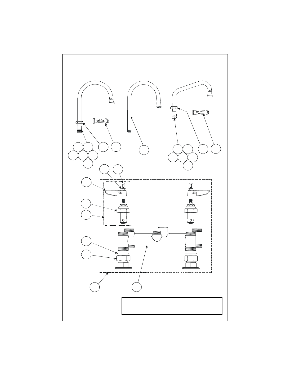
Exploded View
9
2
18141716131119
15
12
13 19
14
15
17
7
6
5
4
3
18
16
8
10
1
* Some items are listed for instructional purposes
and may not be sold as separate parts.
Page 3

Part Number Guide
Body, Swivel Unit 3/8
‘O’-Ring
Body Faucet Assemblies
1 Asm, Faucet (Rigid) B-0320-LN
Asm, Faucet (Swivel) B-0220-LN
2 Faucet Body (Rigid) *
Faucet Body (Swivel) *
3 Asm, Coupling Flange 002893-40
4 Washer 001019-45
5 Asm, Cartridge
6 LH, w/Spring Checks 002711-40
RH, w/Spring Checks 002712-40
LH, w/o Spring Checks 002713-40
RH, w/o Spring Checks 002714-40
7 Handle, Lever - Hot 001637-45
Handle, Lever - Cold 001636-45
8
9 Screw, Handle 000922-45
Index, Button
Hot (Red) 001661-45
Cold (Blue) 001660-45
Nozzle Assemblies
10 Asm, Gooseneck Nozzle 120X
11 Asm, Nozzle Swing
Nozzle, 6” 059X
Nozzle, 12” 062X
Nozzle, 18” 065X
12 Asm, Gooseneck, w/Swing 133X
13 Swivel Piece *
14 Washer, Swivel Piece *
15 Repair Kit 011643-45
16 Sleeve, Swivel *
17 "O"-Ring *
18 Nut, Swivel *
19 Grease Tube 010573-45
Page 4

General Instructions
Nozzle Installation:
Note: Nozzles should be installed
first.
If installing Rigid Gooseneck
1. Apply teflon tape or pipe joint
compound to threaded end of no.9.
2. Tighten no.9 firmly by hand into
no.1.
9
13
16
17
Enlarged view
Faucet Installation:
6. Shut off water supply and drain
lines. Drill (2) two holes, approximately 1-1/4” diameter in countertop
with 8” centers, where you are
installing no.1.
8”[20 cm]
1
If installing Swing Nozzle
3. Insert no.11 or no.12 into no.1 and
rotate to front of sink.
4. Tighten no.11 firmly with a wrench.
12
13, 14,
16, 17
18
11
For swivel repair or replacement of
(‘o’-ring) no.17 and (sleeves) no.16.
5. Insert one no.16 onto no.13. Install
no.17 on no.13 and lubricate liberally
with provided no.19. Install second
no.16 onto no.13. (See enlarged view)
7. Apply teflon tape or pipe joint
compound to water supply lines.
8. Connect no.1 to water supply lines
by screwing no.2 (with eccentric
centers) onto nipple (supplied by
others) and tightening no.2 against
countertop. (Nut under countertop
to be supplied by others). Trim
supply lines if necessary.
1
countertop
water supply line
(supplied by others)
2
nut
9. Turn on water supply and check
for leaks.
Page 5

Instrucciones
Generales
Instalación de la boquilla:
Nota: Las boquillas deben de ser
instaladas primero.
Instalación de la boquilla rígida de
cuello de cisne
1. Aplique al extremo con rosca de la
parte No.9 cinta para rosca de tubería
o compuesto de coyuntura.
2. Aprete firmemente a mano la parte
No.9 entre la parte No.1.
9
1
13
16
Dibujo ampliado
17
Instalación de la canilla:
6. Cierre la fuente principal de agua y
desagüe las tuberias. Perfore dos
huecos apróximadamente de 3 cm de
díametro en el mostrador, con centros
de 20 cm, donde la parte No.1 será
instalada.
8”[20 cm]
Si esta instalando boquilla oscilar
3. Insarte la parte No.11, o No.12 en
la parte No.1 y gire hacia el frente del
lavatorio.
4. Aprete firmemente la parte No.11
con una llave.
12
13, 14,
16, 17
Para el reparo del eje giratorio o
reemplazo de (argolla de goma) parte
No.17 y (manga) No.16.
5. Insarte la parte No.16 en la parte
No.13. Instale la parte No.17 en la
parte No.13 y lubrique liberalmente
con la parte No.19 surtida. Instale la
segunda parte No.16 en la parte
No.13. (Vea el dibujo ampliado)
18
11
7. Aplique cintas para rosca de tubería
o compuesto de coyuntura a las
lineas del surtido de agua.
8. Conecte la parte No.1 a las lineas
del surtido de agua atornillando la
parte No.2 (con los lados excéntricos)
en los tubos (surtidos por otros) y
aprete la parte No.2 contra el
mostrador. (La tuerca debajo del
mostrador esta surtida por otros). Si
es necesario corte las lineas de
surtido.
1
Linea de surtido
9. Abra la fuente de agua e
inspeccione por filtraciones.
(surtidos por otros)
2
mostrador
tuerca
Page 6

Instructions
Générales
L’Installation De L’Ajutage
Noter: Les ajutages devoir être
installer au début
Si vous installer l’ajutage col-decygne
1. Appliquer le ruban en Téflon ou le
composé pour les tuyaux à l’extrémité
de Nº.9.
2. Resserrer Nº.9 fermement par le
main dans Nº.1.
9
1
13
16
17
vue agrandie
L’installation du robinet
6. Fermer la réserve de l’eau et
égoutter la tuyauterie. Percer deux (2)
trous avec un diamètre environ 3 cm.
dans le comptoir avec des centres de
20 cm où vous aller installer Nº.1.
8”[20 cm]
Si vous installer l’ajutage
pivotant
3. Insérer Nº.11 ou Nº.12 dans Nº.1 et
le tourner jusqu’à la face de l’évier.
4. Resserrer Nº.11 fermement avec
une clef.
12
13, 14,
16, 17
Pour la réparation de l’ajutage
pivotant ou le remplacement de
(l’anneau o) Nº.17 et (les manches)
Nº.16
5. Insérer un Nº.16 sur Nº.13.
Installer Nº. 17 sur Nº.13 et lubrifier
libéralement avec le Nº.19 fourni.
Installer l’autre Nº.16 sur Nº.13. (Voir
la vue agrandie).
18
11
7. Appliquer le ruban en Téflon ou le
composé pour les tuyaux aux tuyaux
qui fournir l’eau.
8. Brancher Nº.1 aux tuyaux qui
fournir l’eau en vissant Nº.2 avec les
centres excentriques sur le raccord
(fournir par les autres) et resserrer
Nº.2 contre le comptoir. (L’écrou au-
dessous-du comptoir fournir par les
autres). Couper un peu les tuyaux qui
fournir l’eau si nécessaire.
1
Les tuyaux qui
fournir l’eau
9. Recommencer l’eau et vérifier s’il
y a des fuites.
(fournir par les autres)
2
le comptoir
l’écrou
Page 7

Allgemeine
Anleitungen
Installation des Schwenkarms:
Hinweis: Schwenkarme sind als erstes zu
installieren.
Falls der feststehende Gußauslauf
installiert wird
1. Auf das Gewindeteil von Nr. 9
Teflonband oder Rohrkitt auftragen.
2. Nr. 9 fest mit der Hand in Nr. 1
einschrauben.
9
1
13
16
Vergrößerte Ansicht
17
Installation des Wasserhahns:
6. Wasser abdrehen und Wasserleitungen entleeren. Zwei Löcher mit
einem Durchmesser von 3 cm und
einem Abstand von 20 cm in die
Deckplatte bohren, in die Nr. 1
installiert wird.
8”[20 cm]
Falls Schwenkarm installiert wird
3. Nr.11 oder Nr.12 in Nr.1 einfügen,
auf dem Spültisch nach vorne drehen.
4. Nr.11 mit Schraubenschlüssel
festdrehen.
12
13, 14,
16, 17
Zum Reparieren des Schwenkarms oder
Ersetzen von Nr.17 (O-Ring) und Nr.16
(Muffen):
5. Eine Nr.16 auf Nr.13 aufschieben.
Nr.17 auf Nr.13 installieren und mit
mitgelieferter Nr.19 gut schmieren. Die
zweite Nr.16 auf Nr.13 installieren.
(Siehe vergrößerte Ansicht.)
18
11
7. Teflonband oder Rohrkitt auf
Wasserleitungsrohre auftragen.
8. Nr. 1 an Wasserleitung anschließen,
indem Nr. 2 (mit versetzer Mitte) auf
den Nippel (nicht in der Lieferung
enthalten) aufgeschraubt und gegen
die Deckplatte festgezogen wird.
(Mutter auf der gegenüberliegenden
Deckplatte nicht in der Lieferung
enthalten.) Falls erforderlich,
Wasserleitungen entsprechend
kürzen.
1
Wasserleitungsrohr
(nicht in der Lieferung enthalten)
9. Wasser andrehen und auf
Dichtigkeit prüfen.
2
Abdeckplatte
Mutter
Page 8

RELATED T&S BRASS PRODUCT LINE
B-0245
Deck Mixing Faucet
with 18” Double
Swing Joint Nozzle
T&S BRASS AND BRONZE WORKS, INC.
A firm commitment to application-engineered plumbing products
2 Saddleback Cove, P.O. Box 1088, T & S Brass-Europe
Travelers Rest, SC 29690 ‘De Veenhoeve’
Phone: (864) 834-4102 Oude Nieuwveenseweg 84
Fax: (864) 834-3518 2441 CW Nieuwveen
E-mail: tsbrass@tsbrass.com The Netherlands
 Loading...