

Page 1

Limited One Year Warranty
T&S warrants to the original purchaser (other than
for purposes of resale) that such product is free from
defects in material and workmanship for a period of
one (1) year from the date of purchase. During this
one-year warranty period, if the product is found to
be defective, T&S shall, at its options, repair and/
or replace it. To obtain warranty service, products
must be returned to...
T&S Brass and Bronze Works, Inc.
Attn: Warranty Repair Department
2 Saddleback Cove
Travelers Rest, SC 29690
Shipping, freight, insurance, and other transportation charges of the product to T&S and the return
of repaired or replaced product to the purchaser are
the responsibility of the purchaser. Repair and/or
replacement shall be made within a reasonable time
after receipt by T&S of the returned product. This
warranty does not cover Items which have received
secondary finishing or have been altered or modified after purchase, or for defects caused by physical abuse to or misuse of the product, or shipment
of the products.
Any express warranty not provided herein, and
any remedy for Breach of Contract which might arise,
is hereby excluded and disclaimed. Any implied
warranties of merchantability or fitness for a particular purpose are limited to one year in duration. Under
no circumstances shall T&S be liable for loss of
use or any special consequential costs, expenses
or damages.
Some states do not allow limitations on how long
and implied warranty lasts or the exclusion or limitation of incidental or consequential damages, so
the above limitations or exclusions may not apply
to you. Specific rights under this warranty and other
rights vary from state to state.
P/N: 098-012448-45 Rev.0
Date: 990714
Drawn: CW
Checked: MAB 11-12-99
Approved: MVW 11-13-99
Installation and
Maintenance
Instructions
FAUCET WITH
NOZZLE AND SPRAY
HOSE ASSEMBLY
B-0177
Deutsch: Installations- und
Wartungsanleitungen
Español: la Instalación y las
Instrucciones de
Mantenimiento
Français: les Instructions
d’Installation et
d’Entretien
Page 2

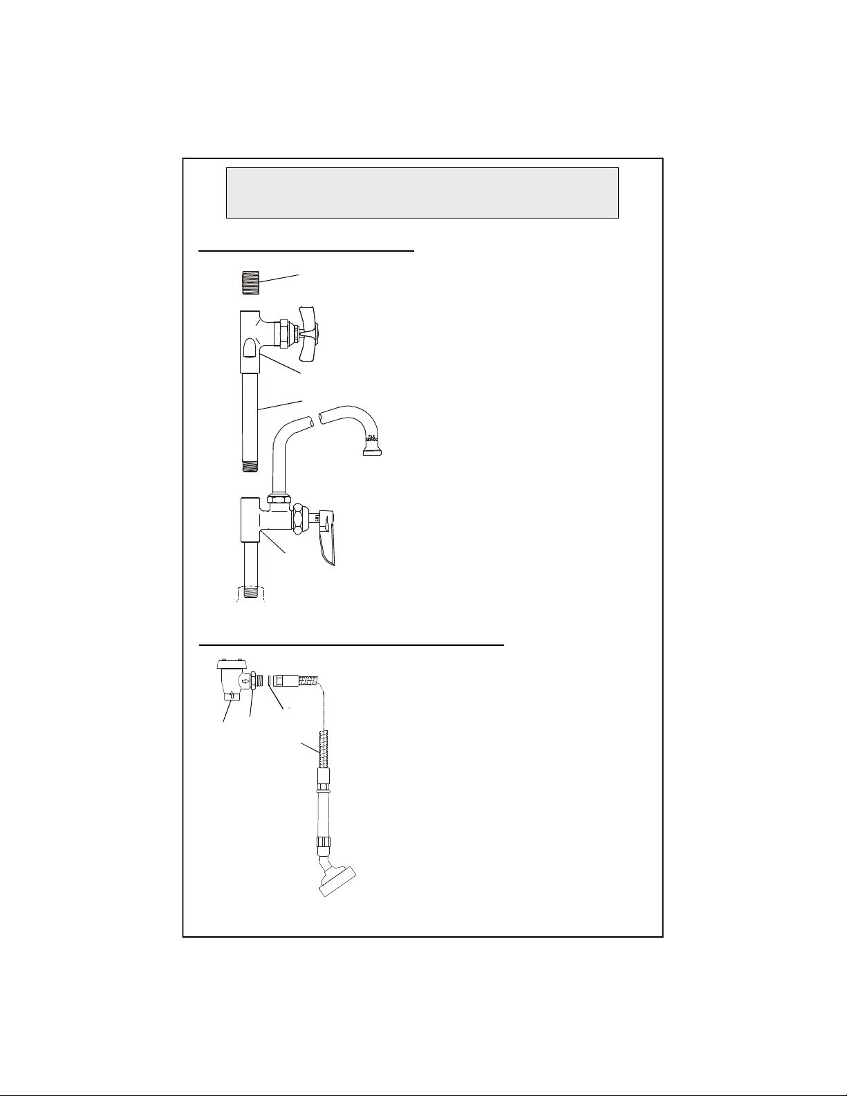
Exploded View
678
10911151617181920212522262932333127283023
24812
13814
125
4
3
* Some items are listed for instructional purposes and may not be sold as separate parts.
2
Page 3

Part Number Guide
1
Asm, Faucet (Rigid)
002829-40
2
Faucet Body (Rigid)
*3Asm, Coupling Flange
002893-40
4
Washer
001019-45
5
Asm, Cartridge
LH, w/Spring Checks
002711-40
RH, w/Spring Checks
002712-40
6
Handle, Lever - Hot
001637-45
Handle, Lever - Cold
001636-45
7
Index, Button
Hot (Red)
001661-45
Cold (Blue)
001660-45
8
Screw, Handle
000922-45
21
Nipple, 3/8" X 4"
*22Valve Body
*23Asm, Cartridge (Cold)
005959-40
24
Handle, 4-Arm
002521-45
25
Grease Tube
*26Nipple
002535-25
28
Adapter, 3/8" MA
000545-25
29
Washer #27
010476-45
30
Asm, Flex S/S Hose
B-0080-H
31
Asm, Spray Head
005969-40
32
Asm, Wall Hook
B-0104-D
33
Screws, Wall Mount
000915-45
9
Asm, Add-on Faucet
B-0155, B-0156, B-0157
005964-40
10
Nipple, 3/8" X 3"
000358-40
11
Faucet Body
*
12
Asm, Cartridge, Quarter Turn
007947-40
13
Handle, Lever (Blank)
001638-45
8
Screw, Handle
000922-45
Faucet Assembly
27 Asm, Vacuum Breaker 3/8" B-0968
Add-On Faucet Assembly
3
Page 4

Part Number Guide - con’t
14
Asm, Nozzle Swing
Nozzle, 6”
059X
Nozzle, 12”
062X
Nozzle, 18”
065X
15
Repair Kit***
011643-45
16
"O"-Ring
*
17
Sleeve, Swivel
*
18
Swivel Piece
*
19
Washer, Swivel Piece
*
20
Nut, Swivel
*
Nozzle Assembly
***Repair kit includes items #16 and #17.
4
Page 5

General Instructions
Nozzle Installation:
Note: Nozzles should be installed
first. See diagram below:
If installing to an existing rigid prerinse unit or base faucet
1. Shut off water supply and drain
lines. Remove no.21 from no.2.
Apply Teflon tape or pipe joint
compound to threaded ends of
no.10.
2. Place no.10 into no.2 and tighten
firmly by hand.
21
14
20
11
10
2
To Install Swing Nozzle:
18
17
Enlarged View
16
Faucet Installation:
1. Drill (2) two holes, approximately
1-1/4” diameter in countertop with 8”
centers, where you are installing
no.2.
8”[20 cm]
2. Apply Teflon tape or pipe joint
compound to water supply lines.
3.Connect no.2 to water supply lines
by screwing no.3 (with eccentric
centers) onto nipple (supplied by
others) and tightening no.3 against
countertop. (Nut under countertop
to be supplied by others). Trim
supply lines if necessary.
1. Insert no.14 into no.11 and rotate
to desired position at sink.
Note: See Repair Kit 011643-45 for
replacement of no.16 and no.17.
2. Tighten no.20 firmly with a wrench.
water supply line
(supplied by others)
5
2
countertop
3
nut
Page 6

General Instructions
Installation of Control Valve:
26
22
21
11
1. Apply Teflon tape on threaded ends of no.21.
Place no.21 into no.22, tighten by hand. Apply
loctite on no.26, insert between no.22 and no.27,
tighten no.27 with a wrench.
2. Apply Teflon tape or pipe joint compound to no.21
and place into no.11 and tighten by hand.
Vacuum Breaker and Hose Installation:
1. Apply Teflon tape on no.28 and place onto no.27.
2. Apply Teflon tape to threaded end of no.28. Attach
no.30 to no.28 (make sure no.29 is in place).
3. Turn on water supply and check for leaks.
4. Install no.32 in a convient location.
27
28
29
30
6
Page 7

Instrucciones
Generales
Instalación de la boquilla:
Nota: Las boquillas deben de ser
instaladas primero. Vea el diagrama
abajo:
Si esta instalando a una unidad
existente rígida de pre-enjuage o a la
base de una canilla
1.Cierre la fuente de agua y desagüe
las tuberías. Remueva la parte No.21
de la parte No.2. Aplique cinta de
Teflon o compuesto de coyuntura a
los extremos con rosca de la parte
No.10.
2. Coloque la parte No.10 dentro la
parte No.2 y apriete firmemente a
mano.
21
18
17
Vista Ampliada
16
Instalación de la Canilla:
1. Perfore (2) dos huecos,
aproximadamente 1¼” de diámetro
con centros de 8” en el mostrador,
donde la parte No.2 será instalada.
8”[20 cm]
2. Aplique cinta de Teflon o
compuesto de coyuntura a las líneas
de surtido.
14
20
11
10
2
Para instalar boquilla
giradora:
1. Inserte la parte No.14 dentro de la
No.11 y gire a una posición deseada
en el lavatorio.
Nota: Vea el estuche de reparos
011643-45 para remplazar las partes
No.16 y No.17.
2. Apriete firmemente la parte No.20
con una llave.
3.Conecte la parte No.2 a las líneas de
surtido atornillando la parte No.3
(con centros excéntricos) al tubo
(surtido por otros) y apriete la parte
No.3 contra el mostrador. (La tuerca
debajo del mostrador será surtida
por otros). Si es necesario recorte las
líneas de surtido.
2
Mostrador
Línea de surtido
(Surtido por otros)
7
3
Tuerca
Page 8

Instrucciones
Generales
Instalación de la Válvula de Control:
26
22
21
11
Instalación de la Manguera y Anti-sifón:
1. Aplique cinta de Teflon a los extremos con rosca de
la parte No.21. Coloque la parte No.21 dentro de la
parte No.22, y apriete a mano. Aplique Loctite en la
parte No.26, y inserte dentro de las partes No.22 y
No.27, Apriete la parte No.27 con una llave.
2. Aplique cinta de Teflon o compuesto de coyuntura
a la parte No.21 colóquela dentro de la parte No.11 y
apriete a mono.
27
28
29
30
1. Aplique cinta de Teflon en la parte No.28 y
colóquela dentro de la parte No.27.
2. Aplique cinta de Teflon al extremo con roscas de la
parte No.28. Junte la parte No.30 a la parte No.28
(asegúrese que la parte No.29 este en su sitio).
3. Abra la fuente de agua e inspeccione por
filtraciones.
4. Instale la parte No.32 en un sitio conveniente..
8
Page 9

Instructions
Générales
L’Installation De L’Ajutage:
Noter: Les ajutages devoir être
installer au début.Voir le
diagramme ci-dessous:
Si vous installer à l’ élément
Prérinçage existant ou le robinet
de la base
1.Fermer la réserve de l’eau et
égoutter la tuyauterie. Enlever Nº.21
de Nº.2. Appliquer le ruban en Téflon
ou le composé pour les tuyaux à
l’extrémité de Nº.10 avec les filets.
2. Resserrer Nº.10 fermement par le
main dans Nº.2.
21
18
17
La Vue Aggrandie
16
L’Installation Du Robinet :
1. Percer (2) deux trous, avec un
diamètre de 1-1/4” dans le comptoir
de l’évier avec les centres de 8”, où
vous aller installer Nº.2.
8”[20 cm]
2.Appliquer le ruban en Téflon ou le
composé pour les tuyaux aux filets
des tuyaux qui fournir l’eau.
14
20
11
10
2
Pour Installer L’Ajutage
D’Entrain:
1. Insérer Nº.14 dans Nº.11 et tourner
jusqu’à la position désirée de l’évier.
Noter: Voir la trousse à outils
011643-45 pour remplacer Nº.16 et
Nº.17.
2. Resserrer Nº.20 fermement avec
une clef anglaise.
3.Brancher Nº.2 aux tuyaux qui
fournir l’eau en branchant Nº.3 (avec
les centres excentriques) sur le
raccord (fournir par les autres) et
resserrer Nº.3 contre le comptoir.
(L’écrou au-dessous-de comptoir
fournir par les autres). Couper un
peu les tuyaux qui fournir l’eau si
nécessaire.
2
Le comptoir
tuyaux qui fournir l’eau
(fournir par les autres)
9
3
l’écrou
Page 10

Instructions
Générales
Installation de soupape de commande:
26
22
21
11
1.Appliquer le ruban en Téflon ou le composé pour
les tuyaux à l’extrémité de Nº.21 avec les filets.
Mettre Nº.21 dans Nº.22 et resserrer par le main .
Appliquer le “Loctite” sur Nº.26, insérer entre Nº.22
et Nº.27, resserrer Nº.27 avec une clef anglaise.
2. Appliquer le ruban en Téflon ou le composé pour
les tuyaux à Nº.21 et mettre dans Nº.11 et resserrer
par le main.
L’Installation De Briseur De Vide et Le Tuyau:
27
28
29
30
1. Appliquer le ruban en Téflon sur Nº.28 et mettre
sur Nº.27.
2. Appliquer le ruban en Téflon à l’extrémité de Nº.28
avec les filets.Attacher Nº.30 à Nº.28.( Soyez certain
que Nº.29 être à sa place).
3. Recommencer l’eau et vérifier s’il y a des fuites.
4. Installer Nº.32 dans un emplacement convenable.
10
Page 11

Allgemeine
Anleitungen
Installation der Schwenkdüse:
Hinweis: Schwenkdüsen sollten als
erstes installiert werden. Sehen Sie
dazu das Diagramm unten:
18
17
Vergrößerte Ansicht
16
Falls an einer bereits vorhandenen
Vorspüleinheit oder einem einfachen
Wasserhahn installiert wird
1. Wasserzufuhr abdrehen und Rohre
leerlaufen lassen. Entfernen Sie Nr. 21
von Nr. 2. Tragen Sie Teflonband oder
Rohrkitt zu den Gewindeenden der
Nr. 10 auf.
2. Setzen Sie Nr. 10 in Nr. 2 und ziehen
Sie es fest von Hand an.
21
14
20
11
10
2
Zur Installation des
Schwenkarmes:
1.Führen Sie Nr. 14 in Nr. 11 ein und
drehen Sie dieses bis die gewünschte
Position am Becken erreicht ist.
Installation des
Wasserhahnes:
1. Bohren Sie (2) zwei Löcher
ungefähr 3 cm (1 1/4") mit einem
Abstand von 20 cm (8") von
Lochmitte zu Lochmitte in die
Arbeitsplatte in der Sie Nr. 2
installieren.
8”[20 cm]
2. Tragen Sie Teflonband oder
Rohrkitt auf die
Wasserzufuhrleitungen auf.
3.Verbinden Sie Nr. 2 zu den
Wasserzufuhrleitungen indem Sie
Nr. 3 (mit versetzter Mitte) auf den
Nippel (nicht in der Lieferung
enthalten) schrauben und Nr. 3 gegen
die Arbeitsplatte festziehen. (Die
Mutter unter der Arbeitsplatte ist
nicht in der Lieferung enthalten).
Falls nötig Wasserzufuhrleitungen
kürzen.
Hinweis: Verweisen Sie zum
Reparaturkit 011643-45 für
Ersatzanweisungen der Nr. 16 und
Nr. 17.
2. Ziehen Sie Nr. 20 mit Hilfe eines
Schraubenschlüssels fest an.
2
Arbeitsplatte
Wasserzufuhrleitungen
(nicht in der Lieferung nthalten)
11
3
Mutter
Page 12
Allgemeine
Anleitungen
Installation des Kontrollventils:
26
22
21
11
1. Tragen Sie Teflonband auf die Gewindeenden der
Nr. 21 auf. Setzen Sie Nr. 21 in Nr. 22 und ziehen Sie
dieses von Hand fest an. Loctite auf Nr. 26 auftragen
und zwischen Nr. 22 und Nr. 27 einfügen, dann Nr. 27
mit einem Schraubenschlüssel fest anziehen.
2. Tragen Sie Teflonband oder Rohrkitt an Nr. 21 auf
und setzen Sie es in Nr. 11, dann von Hand festziehen.
Vakuumsicherungs- und Schlauchinstallation:
1. Teflonband auf Nr. 28 auftragen und zur Nr. 27
aufsetzen.
2. Tragen Sie Teflonband zum Gewindeende der Nr. 28
auf. Befestigen Sie Nr. 30 zur Nr. 28 (stellen Sie sicher,
daß sich Nr. 29 in der richtigen Position befindet).
3. Wasserzufuhr andrehen und auf Dichtheit prüfen.
4. Installieren Sie Nr. 32 an einer günstig gelegenen
Stelle.
27
28
29
30
12
Page 13
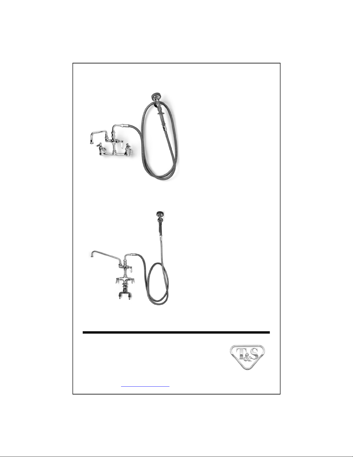
RELATED T&S BRASS PRODUCT LINE
B-0175
Wall Mounted Faucet
with 12” Swing Nozzle
and Spray Unit
B-0176
Deck Mounted Faucet
with 12” Swing Nozzle
and Spray Unit
T&S BRASS AND BRONZE WORKS, INC.
A firm commitment to application-engineered plumbing products
2 Saddleback Cove, P.O. Box 1088, T & S Brass-Europe
Travelers Rest, SC 29690 ‘De Veenhoeve’
Phone: (864) 834-4102 Oude Nieuwveenseweg 84
Fax: (864) 834-3518 2441 CW Nieuwveen
E-mail: tsbrass@tsbrass.com The Netherlands
 Loading...