

Page 1
Limited One Year Warranty
T&S warrants to the original purchaser (other than
for purposes of resale) that such product is free from
defects in material and workmanship for a period of
one (1) year from the date of purchase. During this
one-year warranty period, if the product is found to
be defective, T&S shall, at its options, repair and/
or replace it. To obtain warranty service, products
must be returned to...
T&S Brass and Bronze Works, Inc.
Attn: Warranty Repair Department
2 Saddleback Cove
Travelers Rest, SC 29690
Shipping, freight, insurance, and other transportation charges of the product to T&S and the return
of repaired or replaced product to the purchaser are
the responsibility of the purchaser. Repair and/or
replacement shall be made within a reasonable time
after receipt by T&S of the returned product. This
warranty does not cover Items which have received
secondary finishing or have been altered or modified after purchase, or for defects caused by physical abuse to or misuse of the product, or shipment
of the products.
Any express warranty not provided herein, and
any remedy for Breach of Contract which might arise,
is hereby excluded and disclaimed. Any implied
warranties of merchantability or fitness for a particular purpose are limited to one year in duration. Under
no circumstances shall T&S be liable for loss of
use or any special consequential costs, expenses
or damages.
Some states do not allow limitations on how long
and implied warranty lasts or the exclusion or limitation of incidental or consequential damages, so
the above limitations or exclusions may not apply
to you. Specific rights under this warranty and other
rights vary from state to state.
P/N: 098-005912-45 Rev.2
Date: 980106
Drawn: CW
Checked:
Approved:
MW 6-10-98
MAB 6-10-98
Installation and
Maintenance
Instructions
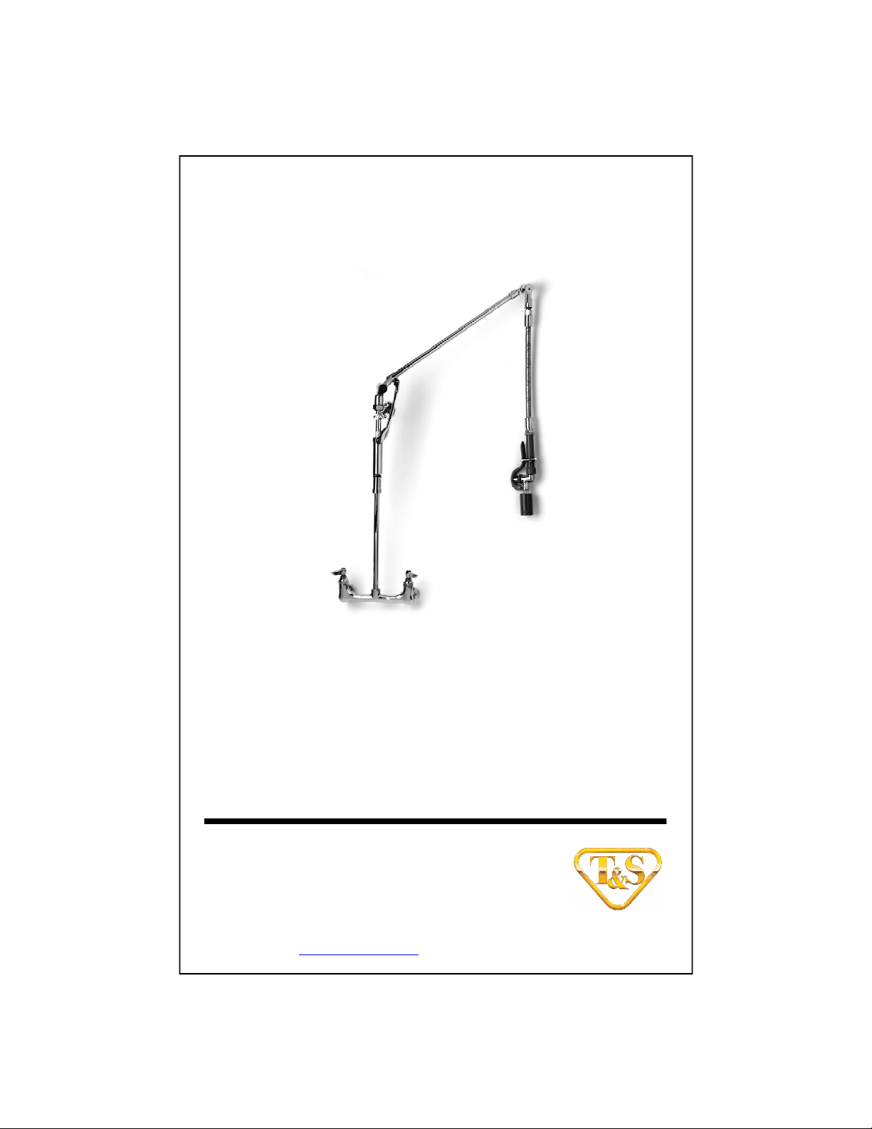
Pre-Rinse Unit
B-0126
(Also for B-0128, B-0129)
(Balancer model with or without vacuum breaker)
Deutsch: Installations- und
Wartungsanleitungen
Español: la Instalación y las
Instrucciones de
Mantenimiento
Français: les Instructions
d’Installation et
d’Entretien
Page 2
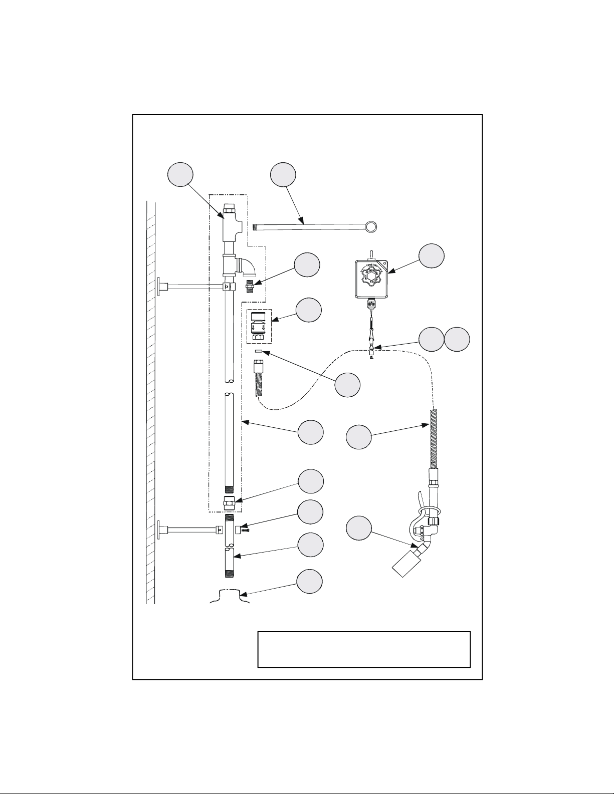
Exploded View
693137
5
1110121415
8
4
2
1
* Some items are listed for instructional purposes
and may not be sold as separate parts.
Page 3

Part Number Guide
Pre-Rinse Unit w/Balancer
1 Asm, Base Faucet *
B-0126, B-0126-VB 002824-40
B-0128, B-0128-VB 002829-40
B-0129, B-0129-VB 002832-40
B-2408-VB B-0157 & 002824-40
B-2409-VB B-0157 & 002832-40
2 Nipple, 3/8"x24" 000372-40
3 Asm, Wall Bracket 6" B-0109-01
4 Asm, Riser
B-0126, B-0128, B-0129 005310-40
B-0126-VB, B-0127-VB, B-0129-VB 005309-40
B-2408-VB, B-2409-VB
5 Asm, Vac. Breaker
6 Coupling, 3/8 Round 001769-40
7 Adapter, 3/8 MA x 3/4-14 MA 000545-25
8 Swivel Tee 005255-40
9 Swivel Arm 005252-45
10 Asm, Balancer & Hardware 005311-40
11 Asm, Hose Clamp *
12 Screws, Hose Clamp *
13 Asm, Flex Hose
B-0126, B-0126-VB, B-0128 B-0068-H
B-0128-VB, B-0129, B-0129-VB
B-2408-VB, B-2409-VB B-0096-H
14 Asm, Spray Valve B-0107-C35
15 Washer, #27
(Included with #12 & #13)
(VB Models)
B-0970-FE
010476-45
Page 4

General Instructions
Installation:
See separate instructions for installation of no.1 into deck.
1. Shut off water supply and drain
lines. Apply teflon tape or pipe joint
compound to threads on both ends of
no.2.
2. Screw no.2 into no.1 and tighten by
hand.
5. Apply a small amount of teflon tape
or pipe thread compound to end of
no.9. Screw no.9 into no.8 at top of
no.4, making sure ring at the end of
no.9 is positioned as shown below.
8
ring
10
9
7
4
wall
6
2
1
3. Screw no.6 onto no.2. Apply teflon
tape or pipe joint compound to bottom
end of no.4. Screw no.4 into no.6.
4. For maximum security and efficiency,
install two no.3.
Note: For models
using no.5, attach
no.5 with no.7 in
place.
7
3
5
4
5
15
13
11,12
6. Attach no.13 to no.5 (if used) or
no.7, make sure no.15 is in place.
7. Install no.10 to no.9 by removing
pin at top of no.10, and attach to ring
of no.9 and replace pin.
8. Assemble no.11 and no.12 to fit
onto no.13, so that the no. 14 hangs
in a convenient place. (Approximately
14” to 18 ½” from work surface.)
9. Turn on water and check for leaks.
Note: Optional Wall Bracket
The no.3 should be installed after
entire unit is assembled. Fit bracket
on no.2 and no.4 as high as possible.
Cut off any excess nipple
(unthreaded end) as needed, and
mount to wall.
Page 5

Instrucciones
Generales
Instalación:
Para la instalación de la parte No.1 en
el mostrador, refiérase a instrucciones
separadas.
1. Cierre la fuente principal de agua y
desagüe las tuberias. Aplique cinta
para rosca de tubo ó compuesto de
coyuntura a las roscas de ambos
extremos de la parte No.2.
2. Atornille la parte No.2 a la parte
No.1 y aprete a mano.
4
5. Aplique una pequeña porción de
cinta para rosca de tubo ó compuesto
para rosca de tubo al extreme de la
parte No.9. Atornille la parte No.9 a la
parte No.8 en la parte de encima de la
parte No.4, asegurándose que el
anillo al extreme de la parte No.9 esté
en la posición como lo muestra abajo.
anillo
8
10
9
7
5
15
11,12
pared
6
2
1
3. Atornille la parte No.6 a la parte
No.2. Aplique cinta para rosca de
tubo ó compuesto de coyuntura a la
parte posterior de la parte No.4.
Atornille la parte No.4 a la parte No.6.
4. Para máxima seguridad y eficencia
instale dos partes No.3.
Nota: (Para
modelos con la
parte No.5) junte
la parte No.5 con
la parte No.7 en
su lugar.
3
7
5
4
13
6. Junte la parte No.13 a la parte No.5
(Si es usado) ó la parte No.7,
asegúrese que la parte No.15 esté
situada.
7. Remuéva la clavija sobre la parte
No.10 para instalar esta parte No.9,
junte la argolla de la parte No.9 y
reemplaze la clavija.
8. Ensamble las partes No.11 y No.12
para que encajen en la parte No.13, a
medida que la parte No.14 cuelgue en
su sitio conveniente. (Aproximadamente de 35 cm a 46 cm de la
superficie de trabajo).
9. Abra el agua e inspeccione por
filtraciones.
Nota: Soporte Opcional Con
Montadura Para la Pared
La parte No.3 debe ser instalada después
de que este ensamblado toda la unidad.
Encaje el soporte de las partes No.2 y
No.4 lo más alto posible. A medida
necesitada, corte el exceso de tubo (extremidad sin rosca) y encajelo a la pared.
Page 6

Instructions
Générales
L’Installation:
Voir les instructions separées pour
l’installation de N°.1 dans la véranda.
1. Fermer la réserve de l’eau et
égoutter la tuyauterie. Appliquer le
ruban en Téflon ou le composé pour
les tuyaux aux filets de chaque
extrémité de N°.2.
5. Appliquer une petite quantité de
ruban en Téflon ou le composé pour
les tuyaux à l’extrémité de N°.9.
Visser N°.9 dans N°.8 au-dessus-de
N°.4, soyez certain que l’anneau a
l’extrémité de N°.9 être en place
comme indiqué au-dessous.
8
l’anneau
10
2.Visser N°.2 dans N°.1 et resserrer par
le main.
4
mur
6
2
1
3. Visser N°.6 sur N°.2. Appliquer le
ruban en Téflon ou le composé pour
les tuyaux au fond de l’extrémité de
N°.4. Visser N°.4 dans N°.6.
4. Pour la securité et l’éfficacité
maximum installer deux N°.3.
Noter: (Pour les
modèles avec un
No.5.) Attacher
No.5 avec No.7 à
sa place.
7
3
5
4
9
7
5
15
13
6. Attacher N°.13 a N°.5 (si utiliser) ou
N°.7, soyez certain que N°.15 être en
place.
7. Installer N°.10 a N°.9 par enlevant
la goupille en haut de N°.10; et
attacher à l’anneau de N°.9 et
remplacer la goupille.
8. Assembler N°.11 et No.12 pour
marcher avec N°.13 pour que N°.14
pendre dans une place convenable.
(Environs 35 cm a 47 cm de la surface
où on travailler.)
9. Recommencer l’eau et vérifier s’il y
a des fuites.
Noter: Le Support Du Mur Facultatif
Le N°.3 devoir être installer après
l’installation d’élément entier.
Mettre le support le plus haut que
possible sur N°.2 et N°.4. Couper le
tuyau excédentaire (l’extrémité sans
filets) comme nécessaire et monter
au mur.
11,12
Page 7

Allgemeine
Anleitungen
Installation:
Bitte separate Anleitungen für
Installation von Nr.1 in Abdeckfläche
beachten.
1. Wasserzufuhr absperren und
Wasser-leitungen entleeren.
Teflonband oder Rohrkitt an beiden
Enden des Gewindes von Teil 2
auftragen.
2. Teil 2 in Teil 1 schrauben und mit
der Hand festziehen.
4
Wand
3. Teil 6 auf Teil 2 aufschrauben.
Teflonband oder Rohrkitt auf
Unterteil von Teil 4 auftragen. Teil 4
in Teil 6 schrauben.
4. Für maximale Sicherheit und
Wirksamkeit zwei Teile Nr.3
installieren.
3
5
4
6
2
1
Anmerkung:
(Für Modelle
mit Teil 5) Nach
Installation von
7 Teil 5 mit Teil
7 verbinden.
7
5. Etwas Teflonband oder Rohrkitt auf
Ende von 9 auftragen. Teil 9 oberhalb
von Teil 4 in Teil 8 einschrauben. Es
ist darauf zu achten, daß Teil 9 wie
unten angegeben positioniert ist.
15
Ring
10
9
7
5
11,12
13
8
6. Teil 12 mit Teil 5 (falls verwendet)
oder Teil 7 verbinden. Es ist darauf zu
achten, daß Teil 14 richtig
ausgerichtet ist
7. Teil 9 in Teil 8 einsetzen, indem Stift
oben von Teil 9 entfernt wird. Mit
Ring von 8 verbinden und Stift
ersetzen.
8. Teil 10 mit Teil 11 so zusammenbauen, daß sie auf Teil 12 passen und
daß Teil 13 an einem bequemen Ort
hängt. (ungefähr 35 cm bis 47 von der
Arbeitsfläche).
9. Wasserleitung öffnen und auf
Lecks prüfen.
Anmerkung: Optionaler Wandarm
Teil 3 muß installiert werden, nach-
dem die gesamte Einheit zusammengesetzt worden ist. Wandarm auf Teil
2 und 4 so hoch wie möglich
anbringen. Überflüssige Nippel
(Ende ohne Gewinde) bei Bedarf
abschneiden und an der Wand
anbringen.
Page 8
RELATED T&S BRASS PRODUCT LINE
B-0137
Pre-Rinse Unit
T&S BRASS AND BRONZE WORKS, INC.
A firm commitment to application-engineered plumbing products
2 Saddleback Cove, P.O. Box 1088, T & S Brass-Europe
Travelers Rest, SC 29690 ‘De Veenhoeve’
Phone: (864) 834-4102 Oude Nieuwveenseweg 84
Fax: (864) 834-3518 2441 CW Nieuwveen
E-mail: tsbrass@tsbrass.com The Netherlands
 Loading...