

Page 1

Limited One Year Warranty
T&S warrants to the original purchaser (other
than for purposes of resale) that such product
is free from defects in material and workmanship for a period of one (1) year from the date
of purchase. During this one-year warranty period, if the product is found to be defective, T&S
shall, at its options, repair and/or replace it. To
obtain warranty service, products must be returned to…
T&S Brass and Bronze Works, Inc.
Attn: Warranty Repair Department
2 Saddleback Cove
Travelers Rest, SC 29690
Shipping, freight, insurance, and other transportation charges of the product to T&S and
the return of repaired or replaced product to the
purchaser are the responsibility of the purchaser. Repair and/or replacement shall be
made within a reasonable time after receipt by
T&S of the returned product. This warranty does
not cover Items which have received secondary finishing or have been altered or modified
after purchase, or for defects caused by physical abuse to or misuse of the product, or shipment of the products.
Any express warranty not provided herein,
and any remedy for Breach of Contract which
might arise, is hereby excluded and disclaimed.
Any implied warranties of merchantability or fitness for a particular purpose are limited to one
year in duration. Under no circumstances shall
T&S be liable for loss of use or any special consequential costs, expenses or damages.
Some states do not allow limitations on how
long and implied warranty lasts or the exclusion or limitation of incidental or consequential
damages, so the above limitations or exclusions
may not apply to you. Specific rights under this
warranty and other rights vary from state to
state.
Installation and
Maintenance
Instructions
B-0114-RK
REPAIR KIT
PRE-RINSE UNIT
Español: la Instalación y las
Instrucciones de
Mantenimiento
P/N: 098-012492-45 Rev. 1
Date: 12-30-04
Drawn: TEH
Checked: MVW 01-04-05
Approved: MVW 01-04-05
Page 2
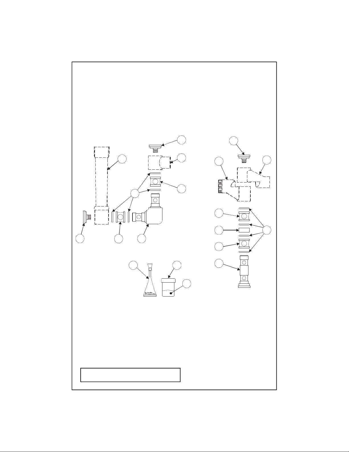
Exploded View
483
5423113101312
7
2
4
* Some items are listed for instructional
purposes and may not be sold as separate parts.
3
1
6
9
2
Page 3

Part Number Guide
Pre-Rinse Unit
1
Asm, Swivel Elbow
009186-40
2
O'Rings
001060-45
Parts Not Included In Kit
3 Delrin Sleeve 008984-45
4 End Cap 008981-25
5 111 Compound *
9 Grease Vial *
6 Loctite *
10 Shaft 008983-25
11 Center Sleeve 008982-45
7 Asm, Grip Handle 002897-40
8 Knuckle, B-0114 #1 *
12 Knuckle, B-0114 #2 *
13 Knuckle, B-0114 #4 *
3
Page 4

General Instructions
To Replace Worn Parts
1. Turn off water supply and drain lines.
2. Remove no.4 from each end of assembly.
4
8
7
2
3
10
11
3
3
13
4
2
1
4
3
2
2
12
3. Carefully pull assembly apart and remove old no’s.1, 2, and 3 and no.10 where
applicable.
4. Clean interior surfaces of no.7 and no.8 or no.12 and no.13, whichever may apply.
5. Apply no.5 to each no.2.
6. If replacing worn parts for the elbow assembly, carefully insert new no.1, with no.2
and no.3 installed, into no.7 and no.8.
7. If replacing worn parts for the upper arm assembly, carefully insert new no.10, with
no.2, no.3 and no.11 installed, into no.12 and no.13.
8. Apply no.6 to threads of no.4 and install no.4 until tight and no’s.7, 8, 12, and/or
13 rotate smoothly.
Note: The B-0114-RK Repair Kit is intended for the “old-style” T&S
knuckle design. If repair parts for the “new-style” are required, contact
T&S Customer Service for correct numbers.
4
Page 5

For 010180 Pre-Rinse Assembly
General Instructions
Repair:
1. Using retaining ring pliers, remove
and discard no.12 from each knuckle
on no.3.
2. Slide Knuckle ‘B’ off shaft. Remove
no.11 and discard, then clean parts and
inspect for damage. If deep scoring
exists, parts must be replaced.
3. Apply thin coat of no.13 to shaft.
Assemble new no.11 onto shaft and
apply a coat of no.13 to no.11.
Knuckle
‘A’
11
12
4. Replace Knuckles and assemble new
no.12.
5. Reassemble unit and check for leaks.
13
Servicing:
Riser Assembly
1. Loosen the two screws on the B-0109 Wall Bracket Clamp.
Knuckle
‘B’
2. Unscrew no.9 from no.3. Disassemble no.5 from no.6.
3. Loosen no.8 on no.4. Carefully slide components from no.5.
4. Inspect no.5 for damage. Inspect the spring for cracks. Replace if necessary.
Apply no.13 to no.11 and reassemble.
5. Reassemble no.5 into no.6 and tighten with a wrench.
6. Tighten clamp screws on B-0109 Wall Bracket.
7. Connect water supply lines and check for leaks.
5
Page 6

Instrucciones
Generales
Para el reemplazo de las partes desgastadas
1. Cierre la fuente de agua y desagüe las tuberías
2. Remueva la parte No.4 de ambos lados del ensamble.
4
8
10
7
2
3
3
11
3
13
4
2
1
4
3. Limpie las superficies interiores de las partes No.7 y No.8 o No.12 y No.13, a las
que sean aplicables.
4. Limpie las superficies interiores de las partes No.7 y No.8 o No.12 y No.13, a las
que sean aplicables.
5. Aplique parte No.5 a ambas partes No.2.
6. Si esta reemplazando partes desgastadas del ensamble de codo, cuidadosamente
inserte una parte nueva No.1 con las partes No.2 y No.3 instaladas dentro de las
partes No.7 y No.8.
7. Si esta reemplazando partes desgastadas para el ensamble del brazo superior,
cuidadosamente ensarte una parte nueva No.10 con las partes No.2, No.3 y No.11
instaladas dentro de las partes No.12 y No.13.
8. Aplique la parte No.6 a las roscas de la parte No.4 e instale la parte No.4 hasta que
este apretada y las partes No.7, 8,12 y/o 13 gire suavemente.
3
2
2
12
Nota: El estuche de reparo B-0114-RK fue hecho para el uso del “estilo
viejo” del diseño de T&S Knuckle. Si se requiere partes para el “estilo
nuevo”, comuníquese con T&S servicio al cliente para los números correctos.
6
Page 7

Instrucciones Para Estuches De Reparo
Para unidades de enjuagar 010180-40
Reparo de junta de chanela:
1. Con alicates para argollas
retenedoras, Remueva y arroje
la parte No.12 de cada chanela en
la parte No.3.
2. Deslize la chanela ‘B’ de el tubo.
Remueva la parte No.11 y arroje,
luego limpie las partes e
inspeccione por danos. Si existen
rayones profundos, la parte
tendrá que ser reemplazada.
3. Aplique una delgada capa de
la parte No.13 a el tubo. En el tubo
arme la parte nueva No.11 y aplique
una delgada capa de la No.13 en
la parte No.11.
4. Reemplaze las chanelas e instale
la parte nueva No.12.
5. Ensamble de nuevo la unidad e
inspeccione por filtraciones.
Mantenimiento:
Ensamble de extensión
Junta
‘A’
11
Junta
‘B’
12
13
1. Afloje los dos atornillos en el soporte B-0109-01.
2. Destornille la parte No.9 de la parte No.3. Desarme la parte No.5 de la parte No.6.
3. Afloje la parte No.8 en la parte No.4. Cuidadosamente deslize los componentes
de la parte No.5.
4. Inspeccione la parte No.5 por daños. Inspeccione el resorte por grietas.
Reemplazelo si es necesario. Aplique de la parte No.13 a la No.11 y arme
de nuevo.
5. Arme de nuevo la parte No.5 en la parte No.6 y aprete con una llave.
6. Aprete los tornillos de soporte B-0109-01.
7. Conecte la tubería principal e inspeccione or filtraciones.
7
Page 8

B-0114
PRE-RINSE UNIT
W/ DECK MOUNTED
FAUCET
T&S BRASS AND BRONZE WORKS, INC.
A firm commitment to application-engineered plumbing products
2 Saddleback Cove, P.O. Box 1088, T & S Brass-Europe
Travelers Rest, SC 29690 ‘De Veenhoeve’
Phone: (864) 834-4102 Oude Nieuwveenseweg 84
Fax: (864) 834-3518 2441 CW Nieuwveen
E-mail: tsbrass@tsbrass.com The Netherlands
 Loading...