

Page 1

Limited One Year Warranty
T&S warrants to the original purchaser (other than
for purposes of resale) that such product is free from
defects in material and workmanship for a period of
one (1) year from the date of purchase. During this
one-year warranty period, if the product is found to
be defective, T&S shall, at its options, repair and/
or replace it. To obtain warranty service, products
must be returned to...
T&S Brass and Bronze Works, Inc.
Attn: Warranty Repair Department
2 Saddleback Cove
Travelers Rest, SC 29690
Shipping, freight, insurance, and other transportation charges of the product to T&S and the return
of repaired or replaced product to the purchaser are
the responsibility of the purchaser. Repair and/or
replacement shall be made within a reasonable time
after receipt by T&S of the returned product. This
warranty does not cover Items which have received
secondary finishing or have been altered or modified after purchase, or for defects caused by physical abuse to or misuse of the product, or shipment
of the products.
Any express warranty not provided herein, and
any remedy for Breach of Contract which might arise,
is hereby excluded and disclaimed. Any implied
warranties of merchantability or fitness for a particular purpose are limited to one year in duration. Under
no circumstances shall T&S be liable for loss of
use or any special consequential costs, expenses
or damages.
Some states do not allow limitations on how long
and implied warranty lasts or the exclusion or limitation of incidental or consequential damages, so
the above limitations or exclusions may not apply
to you. Specific rights under this warranty and other
rights vary from state to state.
P/N: 098-003115-45 Rev.5
Date: 980327
Drawn: CW
Checked: MAB 7-23-98
Approved: MVW 7-23-98
Installation and
Maintenance
Instructions
Kettle And Pot Sink
Faucet
B-0290 and B-0291 Series
Deutsch: Installations- und
Wartungsanleitungen
Español: la Instalación y las
Instrucciones de
Mantenimiento
Français: les Instructions
d’Installation et
d’Entretien
Page 2
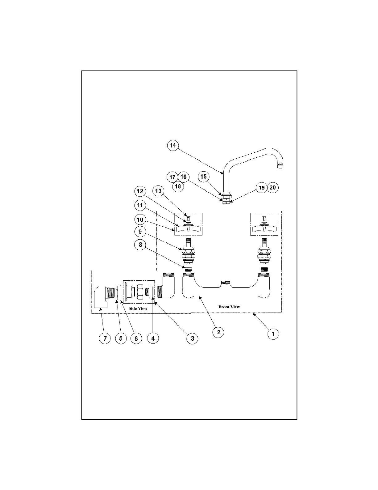
Exploded View
Page 3

Part Number Guide
Faucet Body Assemblies
1 Asm, Base Faucet 002840-40
2 Body, Faucet *
3 Asm, Coupling Flange 002895-40
4 Washer, Coupling Nut 001019-45
5 Locknut 000971-45
6 Washer, Nipple 001005-45
7 El Inlet 000265-20
8 Seat, Removable 000764-20
9 Asm, Spindle 006482-40
10 Asm, Handle RH *
Asm, Handle LH *
11 Handle, 4 Arm Kitchen 002521-45
12 Index, Button (Red - Hot) 001661-45
Index, Button (Blue - Cold) 001660-45
13 Screw, Handle 000922-45
Nozzle Assemblies
14 Asm, Swivel Nozzle - 12 " 114X
Asm, Swivel Nozzle - 18" 115X
15 Nut, Swivel *
16 Swivel Piece *
17 Washer, Swivel *
18 Repair Parts Kit 011643-45
19 Sleeve, Swivel *
20 "O"-Ring *
Page 4

General Instructions
Nozzle Installation:
Note: Nozzles should be installed first.
If installing Swivel Nozzle
1. Place no.14 into no.2 and rotate to
front of sink. Do not wipe grease
from parts.
2. Tighten no.15 firmly with a wrench
14
15
2
Note: See Repair Kit 011643-45
for replacement of no.19 and no.20.
5
6
Shown when
taken out of box
7
6
5
Shown prior to
assembly
7
5. Apply teflon tape or pipe joint
compound to threads of no.7. Hold
no.2 in front of backsplash, and
match no.3 to holes. Connect no.7 to
no.3.
6
5
16
19
insert here
20
Faucet Installation:
3. Shut off water supply and drain
lines. Drill (2) two holes, approximately
1-1/4” diameter in wall or backsplash
of sink with 8” centers, where you are
installing no.1.
8”
4. Remove no.5 and no.6 from no.7.
Reinstall no.5 first, then no.6. Hand
tighten no.3 against no.7.
3
backsplash
or wall
7
6. Tighten no.3 against backsplash
or wall with a wrench.
7. Turn on water supply and check
for leaks.
Note: No.1 can also be installed
with supply lines connected directly
to no.3 (3/4” NPT FE) without
using no.7.
Page 5

Instrucciones
Generales
Instalación De La Boquilla:
Nota: Las boquillas deben de ser
instaladas primero.
Si Esta Instalando Boquilla Oscilar
1. Coloque la parte No.14 entre la
parte No.2 y gire hacia el frente del
lavatorio. No limpie la grasa de las
partes.
2. Con una llave aprete la parte No.15
firmemente.
Nota: Para el reemplazo de las partes
No.19 y No.20, refiérase al estuche de
reparo No. 098-011643-45.
14
15
2
4. Remuéva las partes No.5 y No.6 de
la parte No.7. Instale de nuevo
primero la parte No.5 y después la
parte No.6. Aprete a mano la parte
No.3 contra la parte No.7.
7
5
6
Mostrado antes
de desempacar
5. Aplique cinta para rosca de tubería
o compuesto de coyuntura a las
roscas de la parte No.7. Sostenga la
parte No.2 en frente del espaldar e
iguale la parte No.3 a los huecos.
Conecte la parte No.7 a la parte No.3.
6
5
Mostrado antes
de armar
7
6
5
16
19
20
Instalación De La Canilla:
3. Cierre la fuente principal de agua y
desagüe las tuberias. Perfore (2) dos
huecos, aproximadamente de 3cm de
díametro, en la pared o el aspaldar del
lavatorio, con centros de 20cm, donde
será instalada la parte No.1.
20cm
3
Espaldar ó
Pared
7
6. Aprete la parte No.3 contra el
espaldar o la pared con una llave.
7. Abra la fuente de agua e
inspeccione por filtraciones.
Nota: No.1 también puede ser instalada
con las lineas de surtido conectadas
directamente a la parte No.3. 3/4” NPT
(Rosca de Tubería - Interna) sin usar la
parte No.7.
Page 6

Instructions
Générales
L’Installation De L’Ajutage:
Noter: Les ajutages devoir être
installer au début.
Si Vous Installer L’Ajutage Pivotant
1. Mettre Nº.14 dans Nº.2 et le
tourner jusqu’à la face de l’évier.
N’enlever pas la graisse des parties.
2. Resserrer Nº.15 fermement avec
une clef.
14
15
2
4. Enlever Nº.5 et Nº.6 de Nº.7.
Réinstaller Nº.5 au début, puis Nº.6.
Resserrer Nº.3 par le main contre
Nº.7.
5
6
montré quand
enlever de la
bôite
7
6
5
montré avant
l’assemblage
7
5. Appliquer le ruban en Téflon ou le
composé pour les tuyaux aux filets
de Nº.7. Tenir Nº.2 en face du gardeboue et faire correspondre Nº.3 aux
trous. Brancher Nº.7 à Nº.3.
Noter: Voir la trousse à outils
011643-45 pour remplacer Nº.19 et
Nº.20.
16
insérer ici
19
20
L’Installation Du Robinet:
3. Fermer la réserve de l’eau et
égoutter la tuyauterie. Percer (2) deux
trous avec un diamètre environs 3 cm
dans le mur ou le garde-boue de l’évier
avec les centres de 8”[20 cm], où vous
aller installer Nº.1.
20 cm
6
5
3
le gardeboue ou le
mur
7
6. Resserrer Nº.3 contre le gardeboue ou le mur avec une clef.
7. Recommencer l’eau et vérifier s’il y
a des fuites.
Noter: On pouvoir installer Nº.1
avec les tuyaux qui fournir l’eau
branchés directement à Nº.3 (3/4”
NPT National Pipe Threads female)
sans utilisant Nº.7.
Page 7

Allgemeine
Anleitungen
Schwenkauslaufinstallation:
Anmerkung: Der Schwenkauslauf sollte
zuerst installiert werden.
Bei der Installation eines
beweglichen Schwenkauslaufs
1. Nr.14 in Nr.2 einsetzen und an die
Vorderseite des Spültisches drehen.
Das Fett nicht von den Teilen
entfernen.
2. Nr. 15 mit einem
Schraubenschlüssel festziehen.
14
15
Anmerkung: Siehe Instandsetzungssatz
011643-45 für Ersatz von Nr.19 und
Nr.20.
2
5
6
Ansicht bei
Entfernung aus
der Schachtel
7
6
5
Ansicht vor der
Zusammensetzung
7
5. Teflonband oder Rohrkittmasse
auf das Gewinde von Nr. 7 auftragen.
Nr. 2 vor dem Spritzschutz festhalten
und Nr. 3 auf die Löcher ausrichten.
Nr. 7 mit Nr. 3 verbinden.
6
5
16
19
20
Installation der Armatur:
3. Wasserzufluß sperren und
Leitungen entleeren. (2) zwei Löcher
von ungefähr 3 cm in die Wand oder
den Spritzschutz des Spültisches
bohren mit einem Zwischenabstand
von 20, in die Nr. 1 installiert wird.
20cm
4. Nr. 5 und 6 von Nr. 7 entfernen.
Nr. 5 als erstes wieder installieren,
dann Nr. 6. Mit der Hand Nr. 3 gegen
Nr. 7 festdrehen.
3
Spritzschutz
oder Wand
7
6. Nr. 3 gegen Spritzschutz oder
Wand mit Schraubenschlüssel
festziehen.
7. Wasserzufuhr andrehen und auf
Dichtigkeit prüfen
Anmerkung: Nr. 1 kann auch mit
Zuflußleitungen direkt mit Nr. 3
verbunden werden (3/4” NPT
female) ohne Verwendung von Nr. 7.
Page 8

RELATED T&S BRASS PRODUCT LINE
114X
Big Flow Spout
B-0296
“Big Flow” Faucet
T&S BRASS AND BRONZE WORKS, INC.
A firm commitment to application-engineered plumbing products
2 Saddleback Cove, P.O. Box 1088, T & S Brass-Europe
Travelers Rest, SC 29690 ‘De Veenhoeve’
Phone: (864) 834-4102 Oude Nieuwveenseweg 84
Fax: (864) 834-3518 2441 CW Nieuwveen
E-mail: tsbrass@tsbrass.com The Netherlands
 Loading...