

Page 1
Product: DOC3000X, Revision: 23
Telemetry and data transfer via SATellite
TSAT 3000 User Guide
Hub Station and Remote Terminal
Configuration Parameter (MIB) Description
C30.0.0 – C31.9.0
January 2013
Page 2

TSAT 3000 - Telemetry and data transfer via SATellite
Product description: Hub Station and Remote Terminal Configuration Parameter Description
Document Status
Revision Date CCU Ver Reason for change
1 2007.11.01 30.1.1 First Revision.
2 2008.02.12 30.2.0 Changed UTL_UTILITY_MASK (UTILITY_CCU_LISTEN_TO_CCU).
New
DAC_TCXO_REF
New
DAC_OCXO_REF
Changed
UTL_UTILITY_MASK (UTILITY_ADJUST_TCXO)
Rearranged chapters (ADC / DAC Parameters)
Described ADC + DAC Parameters (New drawing)
Renamed
Removed
ADC_3_TXCO_VOLTAGE to ADC_3_TCXO_VOLTAGE
IP_SUBNET_MASK_{ETH1 | ETH2 | SAT}
Renamed IP_ADDRESS_{ ETH1 | ETH2 | SAT } to …_{ LANA | LANB | SAT }
Described PORT_STREAM_RT (GROUP + CLUSTER Leased Line)
Described
Changed
Described
Changed
PKT_INBOUND_SIZE (Min size of POLL_ACK: 16 => 24)
UTL_DEBUG_MASK (DEBUG_ADDR + DEBUG_SWUL)
LCC_{MIN | MAX}_RETRANS_DELAY (Note)
IP_ROUTE.
3 2008.04.22 30.3.0 Changed UTL_DEBUG_MASK (DEBUG_PPR).
Changed
Described
Described
Described
Changed
New
Changed GAIN_END2END_TAGET (DELTA 0.5 => 0.3 dB).
PHL_SLOT_PHASE_MODE (PPR is implemented).
NET_RT_ADDRESS (Ref. PPR)
PKT_OUTBOUND_SIZE (Ref. PPR)
PKT_INBOUND_SIZE (Ref. PPR)
PHL_INBOUND_GUARDPERIOD (Auto Default value).
NET_NAME
4 2008.05.06 30.3.1 Changed UTL_UTILITY_SEARCH_MASK (KEEP_LOCK_FOREVER).
Described
Described
Changed
5 2008.07.03 30.4.0
30.4.1
Described GAIN_TX_END2END_TARGET (Threshold 1 => 2 packets)
Changed
Changed
New
PORT_PKT_TIMEOUT (Corrected error)
GAIN_TX_END2END_TARGET (DELTA 0.3 => 0.2 dB)
UTL_UTILITY_MASK (TEST_GAIN_WITH_MANY_RTS).
PKT_MAX_SIZE (Minimum 100 => 256)
PHL_SLOT_PHASE_DELAY (Auto function implemented)
SWITCH_{RX | TX}_XXX
Changed SOCK_OPTIONS (DEBUG_PRINT_{RX | TX})
New
UTL_DEBUG_MASK_B
Described PKT_INBOUND_SIZE (IP-address in POLL_ACK)
Changed
PORT_STREAM_RT (Value -1 is IP Routed Line)
6 2008.10.08 30.5.0 Described SYS_IS_HUB (Cannot change via satellite)
Described
Changed
Changed
Changed
Changed
Changed
Changed
Changed
Changed
Changed
Described
Changed
Renamed
UTL_UTILITY_MASK (Cannot change via satellite)
PHL_TX_HUB_FREQUENCY (C-band range)
PHL_TX_RT_FREQUENCY (C-band range)
PHL_TX_HUB_FREQUENCY_BKUP (C-band range)
PHL_TX_RT_FREQUENCY_BKUP (C-band range)
PHL_TX_RT_FREQUENCY_2 (C-band range)
PHL_TX_RT_FREQUENCY_2_BKUP (C-band range)
PHL_{OUTBOUND | INBOUND}_IDENTITY (Changed Default value)
PHL_{OUTBOUND | INBOUND}_IDENTITY (Changed Default value)
PHL_FE_{RX | TX}_LO (C-band range)
PHL_SLOT_PHASE_SETPOINT (1 symbol => ¼ symbol)
GAIN_TX_REF (Limits)
GAIN_TX_END2END_DAC_{MIN | MAX} => GAIN_TX_DAC_{MIN | MAX}
Changed UTL_MIRROR_CHANNEL (101 = Tx RF Level)
Changed
Changed
Described
UTL_UTILITY_SEARCH_MASK (RT_CLEAN_CARRIER)
UTL_DEBUG_MASK (DEFAULT 0x170F)
PHL_DSP_OPTIONS (Rx/Tx Flip)
TSAT 3000 Configuration Parameter Description, January 2013 Page 2 of 124
Page 3

TSAT 3000 - Telemetry and data transfer via SATellite
7 2008.12.01 30.6.0 Included “Named Destination” to all MIB parameters. (PDF lookup)
Described
Described
Changed
Changed
Described
Changed
Changed
8 2009.01.21 30.6.1 Changed MAC_TIMESLOT_MAP_PORT (Implemented now)
9 2009.02.02 30.7.0 Minor PORT_STREAM_RT
Minor
New IP_LINGER_FTP
Changed UTL_DEBUG_MASK (DEBUG_NETWORK)
Changed
10 2009.04.28 30.8.0 Described UTL_UTILITY_MASK (ABS_FREQ_CTRL)
Changed
Changed
Changed
Changed
Changed
Changed
Changed
Described
Described
Corrected
Changed
Described
Changed
Changed
Changed
New
Changed
Changed
Changed
Described
Changed
Changed
Changed
Changed
Changed
Changed
New
New
Changed
Described
11 2009.07.16 31.0.0 Described PHL_BIT_RATE_MODE (Corrected TEST 3)
Changed
New
New
Changed
Described
Described
Described
Described
PORT_TYPE (SERVICE to other HUBs)
SOCK_TYPE (SOCK_NMS to other HUBs)
GAIN_TX_REF (Implemented this function)
PHL_DELTA_SEARCH_FREQUENCY (0 = default)
SYS_HW_REVISION (Revision -1,0,1)
MAC_TIMESLOT_MARGIN (Minimum value on RT)
UTL_UTILITY_SEARCH_MASK (RT_CLEAN_CARRIER_2)
UTL_UTILITY_MASK (option 0x0040)
UTL_DEBUG_MASK_B (DEBUG_NETWORK_{RX | TX})
UTL_DEBUG_MASK_B (DEBUG_MIL)
PHL_DELTA_SEARCH_FREQUENCY (Auto: + 5 kHz)
PHL_INBOUND_IDENTITY_2 (MIL)
PHL_INBOUND_IDENTITY_2_BKUP (MIL)
PHL_TX_RT_FREQUENCY_2 (MIL)
PHL_TX_RT_FREQUENCY_2_BKUP (MIL)
PORT_TX_TREQUENCY_2 (MIL)
PHL_TX_HUB_FREQUENCY_BKUP (Carrier Lock => Open Link)
PHL_TX_RT_FREQUENCY_BKUP (Carrier Lock => Open Link)
MAC_SLOT_MAP_PORT (Ver 30.3.1 => 30.6.1)
NET_{FIRST | LAST}_POLL_RT (MIL)
NET_RT_ADDRESS (MIL + Hub-Connections)
GAIN_TX_REF (Disable when Slave-HUB)
GAIN_TX_OVERRIDE (Disable when Slave-HUB)
GAIN_TX_END2END_TARGET (Disable when Slave-HUB)
PHL_SWITCH_SLAVE_HUB_TIMEOUT (Redunadnt MIL)
PHL_SWITCH_BACK_TO_MAIN_HUB (Redundant MIL)
UTL_UTILITY_MASK (SLAVE_HUB_SWITCHING)
UTL_UTILITY_MASK (CHANGE_CURRENT_TO_DSP)
PHL_DSP_OPTIONS (2150_COMPATIBILITY + XOR)
UTL_UTILITY_MASK (2150_COMPATIBILITY)
UTL_UTILITY_MASK (NOOP_TX_FREQ_2)
UTL_UTILITY_SEARCH_MASK (SEARCH_ONCE + L_LOOP)
UTL_DEBUG_MASK_MASK_B (OUT/INBOUND_LINK_HEAD)
COM_SIGNAL_IN (Range 0…3 => 0…0)
COM_SIGNAL_OUT (Control DSR signal)
COM_SIGNAL_DATA_DELAY (Control DSR signal)
COM_SIGNAL_HOLD (Control DSR signal)
COM_OPTIONS (Console => MSG)
PORT_BIT_RATE (Minimum Baud-Rate)
COM_OPTIONS (KEEP_OPEN + DEBUG_ASCII)
PHL_TX_FREQUENCY_ADJUST
PHL_TX_FREQUENCY_ADJUST_BKUP
NET_NAME (MIB index 137 => 172)
UTL_DEBUG_MASK_B (Version implemented)
UTL_PREFIX_{OUT | IN}_BYTE (Version implemented)
PKT_INBOUND_SIZE (Minimum 27 bytes)
PORT_TYPE (ADAPTER)
TSAT 3000 Configuration Parameter Description, January 2013 Page 3 of 124
Page 4

TSAT 3000 - Telemetry and data transfer via SATellite
12 2009.07.30 31.0.1 Described DAC_{TCXO | OCXO}_REF (new calculation)
New
SWITCH_RX_10MHZ_DELAY (LNB impedance mismatch?)
New
SWITCH_RX_LNB_POWER_DELAY (LNB impedance mismatch?)
13 2009.12.02 31.1.0 Described IP_LINGER_FTP (KERNEL >= 3.2.1)
Described
Described
Described
Described
Described
Described
Described
Changed
Changed
Changed
Described
Described
Described
Renamed
Described
Described
Described
Described
Using
Using
Using
Using
Using
Using
New
14 2010.01.07 31.1.1 Changed COM_OPTIONS (Ignore PFO Errors)
15 2010.05.17 31.1.2
16 2010.09.30
2010.07.12
2010.10.19
2011.02.10
31.1.3
31.2.0
31.2.1
31.3.0
17 2011.06.15 31.4.0
New
Described
Changed
New
PHL_SLOT_PHASE_MODE (DSP >= 2.0.1)
PHL_INBOUND_IDENTITY_2 (RT DSP >= 2.3.1)
PHL_INBOUND_IDENTITY_2_BKUP (RT DSP >= 2.3.1)
PHL_TX_RT_FREQUENCY_2 (RT DSP >= 2.3.1)
PHL_TX_RT_FREQUENCY_2_BKUP (RT DSP >= 2.3.1)
UTL_UTILITY_MASK (2150 comp: DSP >= 2.4.0)
PHL_TX_FREQUENCY_ADJUST (2150 comp: AFA)
UTL_UTILITY_MASK_B (2150 comp: AFA)
UTL_MIRROR_CHANNEL (2150 comp: AFA, ch. 102)
UTL_DEBUG_RT_ADDRESS (2150 comp: AFA)
IP_ADDRESS_{LANA | LANB | SAT} (Error in ver <= 31.0.1)
PHL_SLOT_PHASE_DELAY (Error corrected in 30.5.0/31.1.0)
GAIN_TX_END2END_TARGET (Error corrected in 31.1.0)
ADC_4_TX_GAIN => ADC_4_RX_IF_LEVEL
GAIN_TX_REF (SW incompatibility + Error )
MAC_TIMESLOT_MARGIN (See also Power-Save)
PHL_SLOT_PHASE_MODE (See also Power-Save)
NET_RT_ADDRESS (See also Power-Save)
POW_WAKEUP_FIRST_TIME (Power-Save)
POW_WAKEUP_INTERVAL (Power-Save)
POW_LINK_UP_DURATION (Power-Save)
COM_SIGNAL_IN (Power-Save)
POW_LISTEN_HPA_{ON | OFF} (Power-Save)
POW_LISTEN_POLL (Power-Save)
POW_LISTEN_HPA_MODE (Power-Save)
UTL_TASK_TIMEOUT (Task aliveness)
UTL_DEBUG_MASK_B (DEBUG_PA forgotten in 31.0.0)
UTL_DEBUG_MASK_B (DEBUG_TC)
PORT_REPLY_TIMEOUT (STREAM PORTs)
18 2011.09.20 31.5.0 Described NET_MAX_POLL_SECONDS (Error on RT <= 31.4.0)
MAC_SLOT_REQ_RSV (SRR)
PORT_PRIORITY (SRR - Prio)
LCC_MANAGEMENT_PRIORITY (SRR - Prio)
MAC_TIMESLOT_MAP_0 (SRR - HUB)
UTL_UTILITY_MASK (SATELLITE_SIMULATOR)
UTL_MIRROR_CHANNEL (Delta UW Position)
UTL_DEBUG_MASK (DEBUG_DSP_MSG)
POW_xxx (PDF Named destinations)
PHL_SWITCH_BACK_TO_MAIN_HUB (Switching functionality)
MAC_SLOT_REQ_RSV (SRR_OPTION)
UTL_UTILITY_SEARCH_MASK (SEARCH_TEST_BW / OCXO)
19 2011.10.20
2011.11.03
2012.01.09
20 2012.01.19
2012.03.14
2012.03.23
31.5.1
31.5.2
31.6.0
31.6.1
31.7.0
31.7.1
Implemented
Described
Described
Described
Changed
Changed
Changed
Corrected
Described
Changed
Changed
TSAT 3000 Configuration Parameter Description, January 2013 Page 4 of 124
Page 5
TSAT 3000 - Telemetry and data transfer via SATellite
21 2012.08.16 31.8.0 New MAC_SLOT_REQ_RSV_SOURCE (Slot Request and Reservation)
Described
Described
Changed
New
Descr
Descr
Descr
Corrected document “Title” and “Company”
22 2012.09.03 31.8.1 Descr PHL_TX_FREQUENCY_ADJUST (Really HOT)
MAC_SLOT_REQ_RSV (Source of data)
PORT_PRIORITY (Ref PORT_OPTIONS)
PORT_OPTIONS (OPTION_PRIORITY_FIXED)
PORT_SWITCH_TIMEOUT (App T.O. => Switch HUB)
PHL_SWITCH_BACK_TO_MAIN_HUB (Ref PORT_SWITCH_TIMEOUT)
PHL_SWITCH_SLAVE_HUB_TIMEOUT (Ref PORT_SWITCH_TIMEOUT)
UTL_UTILITY_SEARCH_MASK (UTILITY_SEARCH_DSP_IS_HUB)
23 2012.10.22
2013.01.28
31.8.2
31.9.0 Described UTL_UTILITY_MASK (UTILITY_REBOOT_CONTIN)
Described
Described
New
UTL_UTILITY_MASK (UTILITY_ABS_FRQ_CTRL)
MAC_SLOT_REQ_RSV (SYS_LICENCE)
SYS_LICENCE (ACL + SRR)
TSAT 3000 Configuration Parameter Description, January 2013 Page 5 of 124
Page 6

TSAT 3000 - Telemetry and data transfer via SATellite
Documentation Comment Form
TSAT AS encourages you to comment on the documentation supplied with our products. This
information helps us to provide quality products to meet your needs.
Edition Date: January 2013
Product: DOC3000X23
Please comment on the correctness, completeness, clarity, organisation and usefulness of the
manual.
If you find errors in the manual, please record the page numbers and describe the errors.
Thank you for your help.
Name___________________________________________________________________
Title_____________________________________________________________________
Company_________________________________________________________________
Address__________________________________________________________________
Phone (________)________________________________________________________
Following documentation is available for the TSAT 3000 system:
• DOC3000X; System Description
• DOC3000X; Product Guide
• DOC3000X; Hub Station and Remote Terminal Configuration Parameter Description
• DOC3000X; Hardware Configuration Guide
• DOC3000X; Hub Station and Remote Terminal Installation, Operation and Maintenance Guide
• DOC2010B; Supervisory Terminal User Guide; TSAT 2000 / 2100 / 2150 / 3000
AV SatCom AS makes no warranty of any kind with regard to this material, including, but not limited to, the implied
warranties of merchantability and fitness for a particular purpose. AV SatCom AS assumes no responsibility for any errors
that may appear in this document. AV SatCom AS makes no commitment to update or to keep current the information
contained in this document. Specifications and procedures may change at any time without notice. No part of this
document may be copied or reproduced in any form or by any means without prior written consent of AV SatCom AS.
Brand names used in this document are the property of their respective owners. Company and product names are
trademarks or registered trademarks of their respective companies.
TSAT 3000 Configuration Parameter Description, January 2013 Page 6 of 124
Page 7

TSAT 3000 - Telemetry and data transfer via SATellite
Table of contents
1. SCOPE..............................................................................................................................................................11
2. GENERAL .......................................................................................................................................................11
3. MIB PARAMETER DESCRIPTION ................................................................................................... .........12
3.1 PORT PARAMETERS....................................................................................................................................12
3.1.1 PORT_MAX_PORTS................................................................................................................................13
3.1.2 PORT_TYPE [n] ......................................................................................................................................13
3.1.3 PORT_USE_SOCKET [n] .......................................................................................................................14
3.1.4 PORT_USE_COM [n] .............................................................................................................................14
3.1.5 PORT_BIT_RATE [n]..............................................................................................................................15
3.1.6 PORT_DATA_BITS [n]............................................................................................................................15
3.1.7 PORT_STOP_BITS [n]............................................................................................................................15
3.1.8 PORT_PARITY [n] ..................................................................................................................................16
3.1.9 PORT_FLOW_CTRL [n] .........................................................................................................................16
3.1.10 PORT_PRIORITY [n] ............................................................................................................................17
3.1.11 PORT_PKT_TIMEOUT [n]................................................................................................................... 18
3.1.12 PORT_FORWARD_CHAR [n] ..............................................................................................................19
3.1.13 PORT_MAX_PKT_SIZE [n]..................................................................................................................20
3.1.14 PORT_TX_QUEUE_SIZE [n] ...............................................................................................................21
3.1.15 PORT_REPLY_TIMEOUT [n]...............................................................................................................22
3.1.16 PORT_SWITCH_TIMEOUT [n]............................................................................................................23
3.1.17 PORT_OPTIONS [n].............................................................................................................................24
3.1.18 PORT_STREAM_RT [n]........................................................................................................................26
3.1.19 PORT_STREAM_RT_PORT [n]............................................................................................................28
3.1.20 PORT_MAX_APPL_RETRIES [n].........................................................................................................29
3.1.21 PORT_TX_FREQUENCY_2 [n]............................................................................................................29
3.2 SOCKET PARAMETERS...............................................................................................................................30
3.2.1 SOCK_MAX_SOCKETS...........................................................................................................................31
3.2.2 SOCK_TYPE [n]......................................................................................................................................31
3.2.3 SOCK_PROTOCOL [n]...........................................................................................................................31
3.2.4 SOCK_ADDRESS [n] ..............................................................................................................................31
3.2.5 SOCK_LOCAL_PORT [n].......................................................................................................................32
3.2.6 SOCK_REMOTE_PORT [n]....................................................................................................................32
3.2.7 SOCK_OPTIONS [n]...............................................................................................................................33
3.2.8 SOCK_IDLE_TIMEOUT [n] ...................................................................................................................35
3.2.9 SOCK_CONNECT_TIMEOUT [n]..........................................................................................................35
3.3 COM PARAMETERS.....................................................................................................................................36
3.3.1 COM_MAX_COMS..................................................................................................................................36
3.3.2 COM_SIGNAL_IN [n] .............................................................................................................................36
3.3.3 COM_SIGNAL_OUT [n] .........................................................................................................................37
3.3.4 COM_SIGNAL_DATA_DELAY [n].........................................................................................................38
3.3.5 COM_SIGNAL_HOLD [n] ......................................................................................................................38
3.3.6 COM_OPTIONS [n] ................................................................................................................................39
3.4 IP PARAMETERS...........................................................................................................................................40
3.4.1 IP_ADDRESS_{ETH1 | ETH2 | SAT}......................................................................................................40
3.4.2 IP_SUBNET_MASK_{ETH1 | ETH2 | SAT}............................................................................................40
3.4.3 IP_ADDRESS_{LANA | LANB | SAT} .....................................................................................................41
3.4.4 IP_ROUTE [n].........................................................................................................................................44
3.4.5 IP_LINGER_FTP.....................................................................................................................................46
TSAT 3000 Configuration Parameter Description, January 2013 Page 7 of 124
Page 8

TSAT 3000 - Telemetry and data transfer via SATellite
3.5 ADC + DAC PARAMETERS..........................................................................................................................47
3.5.1 ADC_SAMPLE_COUNT..........................................................................................................................48
3.5.2 ADC_{1 | 2 | 3 | 4 | 5 | 6 | 7 | 8}_XXX......................................................................................................48
3.5.3 DAC_{11 | 12 | 13 | 14 | 21 | 22 | 23 | 24}_XXX......................................................................................48
3.5.4 DAC_{TCXO | OCXO}_REF...................................................................................................................49
3.6 SWITCH PARAMETERS...............................................................................................................................50
3.6.1 SWITCH_{RX | TX}_XXX........................................................................................................................50
3.6.2 SWITCH_RX_{10MHZ | LNB_POWER}_DELAY...................................................................................50
3.7 GAIN PARAMETERS....................................................................................................................................51
3.7.1 GAIN_TX_REF ........................................................................................................................................51
3.7.2 GAIN_TX_OVERRIDE ............................................................................................................................52
3.7.3 GAIN_TX_END2END_TARGET.............................................................................................................53
3.7.4 GAIN_TX_DAC_{MIN | MAX}................................................................................................................54
3.7.5 GAIN_RX_ATTENUATOR.......................................................................................................................54
3.8 LINK LAYER PARAMETERS.......................................................................................................................55
3.8.1 LCC_TX_QUE_SIZE ...............................................................................................................................57
3.8.2 LCC_RETRANS_QUE_SIZE ...................................................................................................................57
3.8.3 LCC_WINDOW_SIZE..............................................................................................................................58
3.8.4 LCC_MAX_LINK_RETRIES....................................................................................................................59
3.8.5 LCC_MAX_{APPL | MNGT}_PKT_AGE................................................................................................59
3.8.6 LCC_MANAGEMENT_PRIORITY..........................................................................................................60
3.8.7 LCC_{MIN | MAX}_RETRANS_DELAY..................................................................................................60
3.8.8 LCC_{MIN | MAX}_RESET_RETRANS_DELAY....................................................................................60
3.9 MEDIA ACCESS PARAMETERS .................................................................................................................61
3.9.1 MAC_TIMESLOTS_IN_FRAME..............................................................................................................61
3.9.2 MAC_ACCESS_SCHEME .......................................................................................................................61
3.9.3 MAC_ACCESS_SCHEME_2 ...................................................................................................................61
3.9.4 MAC_SLOT_MAP_{0 | 1 | 2 | 3} .............................................................................................................62
3.9.5 MAC_SLOT_MAP_PORT........................................................................................................................63
3.9.6 MAC_SLOT_REQ_RSV ...........................................................................................................................64
3.9.7 MAC_SLOT_REQ_RSV_SOURCE..........................................................................................................68
3.9.8 MAC_TIMESLOT_LENGTH ...................................................................................................................69
3.9.9 MAC_TIMESLOT_MARGIN....................................................................................................................69
3.10 NETWORK PARAMETERS ........................................................................................................................70
3.10.1 NET_NO_OF_RTS.................................................................................................................................70
3.10.2 NET_RT_ADDRESS...............................................................................................................................70
3.10.3 NET_NAME............................................................................................................................................70
3.10.4 NET_{FIRST | START | LAST}_POLL_RT............................................................................................71
3.10.5 NET_MAX_POLL_SECONDS...............................................................................................................72
3.10.6 NET_GROUPS [1…5] ...........................................................................................................................73
TSAT 3000 Configuration Parameter Description, January 2013 Page 8 of 124
Page 9

TSAT 3000 - Telemetry and data transfer via SATellite
3.11 PHYSICAL LAYER PARAMETERS...........................................................................................................74
3.11.1 PHL_{OUTBOUND | INBOUND}_SYMBOLRATE..............................................................................74
3.11.2 PHL_{OUTBOUND | INBOUND}_MODULATION ............................................................................. 74
3.11.3 PHL_{OUTBOUND | INBOUND}_FECRATE .....................................................................................75
3.11.4 PHL_{OUTBOUND | INBOUND}_FECTYPE......................................................................................75
3.11.5 PHL_{OUTBOUND | INBOUND}_FILTERTYPE................................................................................76
3.11.6 PHL_{OUTBOUND | INBOUND}_FILTERALFA................................................................................76
3.11.7 PHL_INBOUND_GUARDPERIOD.......................................................................................................76
3.11.8 PHL_IN_OUT_PACKET_RATIO..........................................................................................................77
3.11.9 PHL_DSP_OPTIONS ............................................................................................................................77
3.11.10 PHL_SLOT_PHASE_MODE...............................................................................................................78
3.11.11 PHL_SLOT_PHASE_SETPOINT.........................................................................................................82
3.11.12 PHL_SLOT_PHASE_DELAY ..............................................................................................................83
3.11.13 PHL_TARGET_UW_POSITION..........................................................................................................84
3.11.14 PHL_{OUTBOUND | INBOUND}_IDENTITY...................................................................................85
3.11.15 PHL_{OUTBOUND | INBOUND}_IDENTITY_BKUP.......................................................................85
3.11.16 PHL_INBOUND_IDENTITY_2...........................................................................................................85
3.11.17 PHL_INBOUND_IDENTITY_2_BKUP...............................................................................................85
3.11.18 PHL_TX_HUB_FREQUENCY ............................................................................................................86
3.11.19 PHL_TX_RT_FREQUENCY................................................................................................................86
3.11.20 PHL_TX_HUB_FREQUENCY_BKUP................................................................................................86
3.11.21 PHL_TX_RT_FREQUENCY_BKUP ...................................................................................................86
3.11.22 PHL_TX_RT_FREQUENCY_2............................................................................................................87
3.11.23 PHL_TX_RT_FREQUENCY_2_BKUP ...............................................................................................90
3.11.24 PHL_TX_FREQUENCY_ADJUST ......................................................................................................91
3.11.25 PHL_TX_FREQUENCY_ADJUST_BKUP..........................................................................................92
3.11.26 PHL_SWITCH_BACK_TO_MAIN_HUB.............................................................................................93
3.11.27 PHL_SWITCH_SLAVE_HUB_TIMEOUT...........................................................................................94
3.11.28 PHL_DELTA_SEARCH_FREQUENCY..............................................................................................95
3.11.29 PHL_SAT_CONVERT_FREQUENCY.................................................................................................96
3.11.30 PHL_FE_RX_LO ........................................................................................................... ...................... 96
3.11.31 PHL_FE_TX_LO..................................................................................................................................96
3.12 PACKET PARAMETERS.............................................................................................................................97
3.12.1 PKT_MAX_SIZE....................................................................................................................................97
3.12.2 PKT_OUTBOUND_SIZE.......................................................................................................................97
3.12.3 PKT_INBOUND_SIZE...........................................................................................................................98
3.12.4 PKT_POOL_SIZE..................................................................................................................................98
3.13 POWER PARAMETERS..............................................................................................................................99
3.13.1 POW_WAKEUP_FIRST_TIME...........................................................................................................100
3.13.2 POW_WAKEUP_INTERVAL...............................................................................................................101
3.13.3 POW_LINK_UP_DURATION.............................................................................................................101
3.13.4 POW_LISTEN_HPA_MODE...............................................................................................................102
3.13.5 POW_LISTEN_HPA_ON.....................................................................................................................103
3.13.6 POW_LISTEN_HPA_OFF...................................................................................................................103
3.13.7 POW_LISTEN_POLL ..........................................................................................................................104
3.14 SYSTEM PARAMETERS ..........................................................................................................................105
3.14.1 SYS_IS_HUB........................................................................................................................................105
3.14.2 SYS_COPYRIGHT................................................................................................................................105
3.14.3 SYS_HW_REVISION............................................................................................................................105
3.14.4 SYS_CONFIG_VERSION ....................................................................................................................105
3.14.5 SYS_VERSION .....................................................................................................................................106
3.14.6 SYS_DATE ...........................................................................................................................................106
3.14.7 SYS_TIME............................................................................................................................................106
3.14.8 SYS_LICENCE.....................................................................................................................................107
TSAT 3000 Configuration Parameter Description, January 2013 Page 9 of 124
Page 10

TSAT 3000 - Telemetry and data transfer via SATellite
3.15 UTILITY PARAMETERS ..........................................................................................................................108
3.15.1 UTL_LOG_SIZE ..................................................................................................................................108
3.15.2 UTL_LOG_SAVE_INTERVAL.............................................................................................................108
3.15.3 UTL_TASK_TIMEOUT........................................................................................................................108
3.15.4 UTL_MIRROR_CHANNEL..................................................................................................................109
3.15.5 UTL_{OUTBOUND | INBOUND}_PREFIX_BYTE............................................................................110
3.15.6 UTL_DEBUG_MASK ..........................................................................................................................111
3.15.7 UTL_DEBUG_MASK_B...................................................................................................................... 113
3.15.8 UTL_DEBUG_IPC_MASK.................................................................................................................. 114
3.15.9 UTL_DEBUG_RT_ADDRESS.............................................................................................................114
3.15.10 UTL_INDICATOR_MODE..................................................................................................... ........... 114
3.15.11 UTL_UTILITY_MASK........................................................................................................................115
3.15.12 UTL_UTILITY_SEARCH_MASK.......................................................................................................118
4. MIB INDEX SUMMARY.............................................................................................................................121
TSAT 3000 Configuration Parameter Description, January 2013 Page 10 of 124
Page 11
TSAT 3000 - Telemetry and data transfer via SATellite
1. SCOPE
This document describes the configuration parameters in the .SAT file used to store CCU
configuration. The purpose, and legal values, of each parameter is described.
2. GENERAL
Unless otherwise stated, all MIB parameters described here are present in the TSAT 3000 CCU
software versions C30.0.0 to C31.9.0. Generally, unless otherwise stated by some of the qualifiers
below, all MIB parameters may be read and written, all MIB parameters will survive a RESTART of
the CCU, and all CURRENT MIB parameters may be changed while the CCU is running (change will
take effect immediately). The exception qualifiers are:
BOOT:
Read-Only:
Volatile:
No-Current:
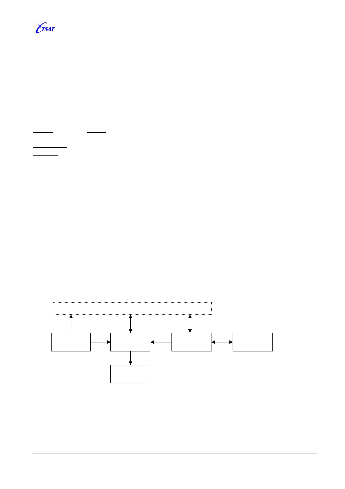
Within the CCU, each MIB variable may have up to 5 different values:
• DEFAULT is a table with default values stored in PROM.
• FILE is a table of MIB variables that will survive a restart of the CCU, and stored in the .SAT
• CACHE is a RAM copy of the FILE table. It is initialised from the FILE values during start-up of
• CURRENT is the table with values that is actually used. It is initialised from DEFAULT
• LOCAL is local copies (or transformations) of the CURRENT variables that may be used within
You cannot change the CURRENT value. Operator has to change the CACHE value,
flush CACHE to FILE and RESET the CCU to activate the new configuration.
No CACHE or DEFAULT value. You can only read the CURRENT value.
No CASHE value. You can both read and write CURRENT value, but it will not
survive a RESTART of the CCU.
Some of the MIB parameters (i.e. the Backup Frequency parameters) don’t have
CURRENT values.
configuration file. MIB variables that doesn’t have an FILE value will not survive a CCU reset,
and are also called ‘Volatile’ variables.
the CCU, and it will be copied back to the FILE when the operator is doing a SAVE (also called
FLUSH) operation.
immediately after CCU reset, and when the variables has been successfully copied from FILE to
CACHE, it will be initialised from CACHE (replace the DEFAULT configuration).
some of the software modules. MIB variables that have a LOCAL value are also called ‘BOOT’
variables. I.e: The operator must change the CACHE value, flush the CACHE to FILE and
RESET the CCU to activate the new configuration.
Supervisory Terminal
DEFAULT
CURRENT
LOCAL
CACHE
FILE
From the ‘Management Information Base’ and ‘CCU Configuration’ windows in the Supervisory
Terminal the operator may select to:
• READ the DEFAULT, CURRENT or CACHE variables. The LOCAL values cannot be read.
• WRITE the variable to CURRENT or CACHE. The DEFAULT or LOCAL values cannot be written.
• SAVE the content of CACHE to FILE (also called FLUSH).
TSAT 3000 Configuration Parameter Description, January 2013 Page 11 of 124
Page 12
TSAT 3000 - Telemetry and data transfer via SATellite
3. MIB PARAMETER DESCRIPTION
3.1 PORT PARAMETERS
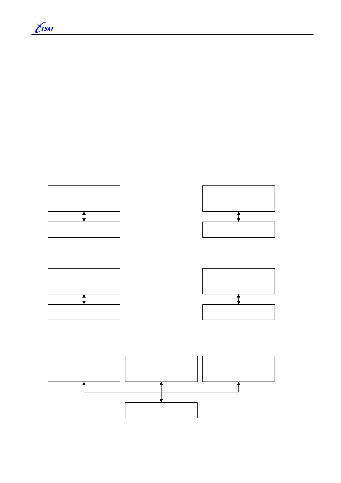
All communication to/from the CCU is through (logical) PORTs. The PORT must be configured to
use a specified (physical) Interface (COM, SOCKET or IP-STACK).
In general, any PORT (STREAM, SERVICE or ADAPTER) may use any COM or SOCKET (RAW_
DATA
, TSAT_NMS or COMPORT_SERVER). Exception: The NETWORK PORT_TYPE [n] will always be
connected to IP-STACK. You are free to connect one Interface to many PORTs, but you cannot
connect one PORT to many Interfaces.
Data received on PORT will be sent to destination unit, defined by PORT_STREAM_RT [n] and
PORT_STREAM_RT_PORT [n]. For test purposes, data received and sent to any PORT, COM or
SOCKET may be looped.
Some examples of how you may connect PORTs to Interfaces:
Use PORT 2 for STREAM data on COM 2
Use PORT 5 for STREAM data on SOCKET 2
TYPE = STREAM
USE_SOCKET = 0
USE_COM = 2
PORT 2
COM 2
Use PORT 4 for SERVICE data on SOCKET 1
TYPE = SERVICE
USE_SOCKET = 1
USE_COM = n/a
TYPE = TSAT_NMS
PORT 4
SOCKET 1
TYPE = STREAM
USE_SOCKET = 2
USE_COM = n/a
TYPE = RAW_DATA
Use PORT 3 for NETWORK (IP) data
TYPE = NETWORK
USE_SOCKET = n/a
USE_COM = n/a
PORT 5
SOCKET 2
PORT 3
IP-STACK
Connect PORT 7, 8 and 9 to Remote COM 10, 11 and 12 at “TSAT Comport Server”
TYPE = SERVICE
USE_SOCKET = 3
USE_COM = 10
PORT 7
TYPE = STREAM
USE_SOCKET = 3
USE_COM = 11
TYPE = COMPORT_SERVER
PORT 8
SOCKET 3
TYPE = ADAPTER
USE_SOCKET = 3
USE_COM = 12
PORT 9
TSAT 3000 Configuration Parameter Description, January 2013 Page 12 of 124
Page 13
TSAT 3000 - Telemetry and data transfer via SATellite
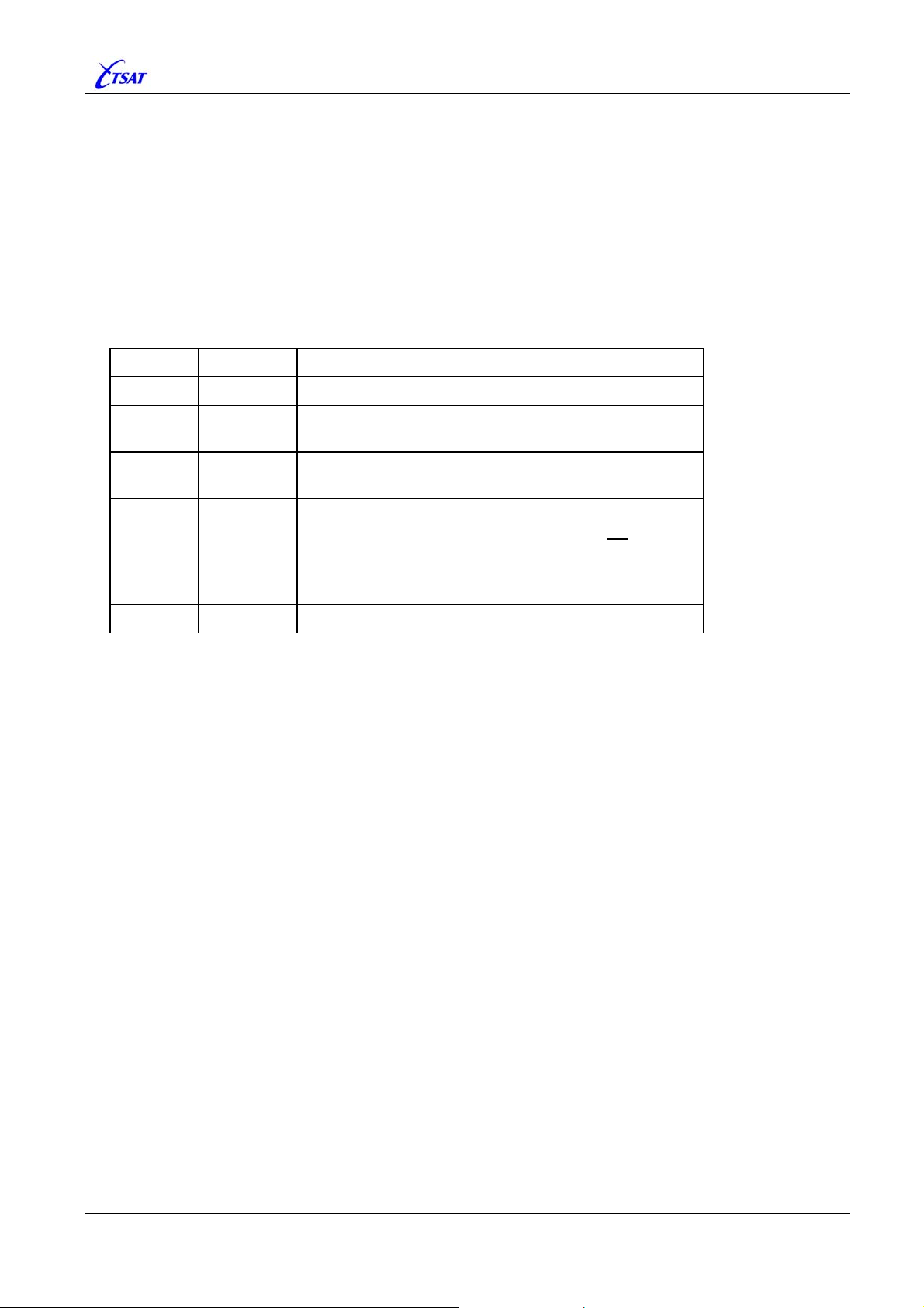
3.1.1 PORT_MAX_PORTS
Default 4, Range 1…64
Set number of PORTs.
3.1.2 PORT_TYPE [n]
Default 0, Range 0…4
Set Type of data on this PORT.
Value Mnemonic Description
0 NONE Closed.
1 STREAM
2 SERVICE
3 ADAPTER
4 NETWORK IP Network.
Raw byte stream data. The input bytes are transferred
transparently through the TSAT network.
TSAT Management protocol. Connected to NMS.
HUB Ver >= 30.4.0: Also connect to other HUBs.
Protocol Adapter.
Ver <= 30.8.0: Not implemented. PORT will not
Ver >= 31.0.0:
RT: Implemented OK.
HUB: PORT will be treated as STREAM.
operate.
TSAT 3000 Configuration Parameter Description, January 2013 Page 13 of 124
Page 14
TSAT 3000 - Telemetry and data transfer via SATellite
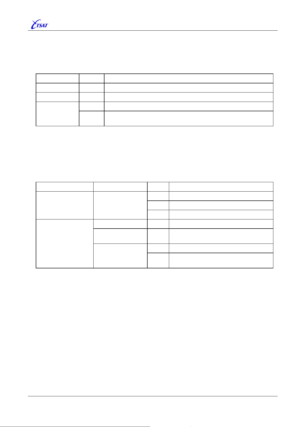
3.1.3 PORT_USE_SOCKET [n]
Default 0, Range 0…32
Set SOCKET connection to this PORT.
Usage is dependent on
PORT_TYPE [n]
NONE n/a Not Used when PORT is Closed.
NETWORK n/a Not Used when PORT is connected to IP-STACK.
SERVICE
ADAPTER
PORT_TYPE [n].
Value Description
0 PORT is connected to Local-COM (defined by PORT_USE_COM [n]). STREAM
1 … 32
PORT is connected to a SOCKET.
Protocol on this SOCKET is defined by
SOCK_TYPE [n].
3.1.4 PORT_USE_COM [n]
Default 0, Range 0…64
Set COM connection to this PORT.
Usage is dependent on
PORT_USE_SOCKET [n] SOCK_TYPE [n]
PORT_USE_SOCKET [n] and SOCK_TYPE [n].
Value Description
0 PORT isn’t connected to any Local-COM.
0 n/a
1 … 8 PORT is connected to Local-COM.
9 … 64 INVALID.
NONE n/a Not Used when SOCKET is Closed.
RAW_DATA
TSAT_NMS
n/a Not Used.
1 … 32
0 PORT isn’t connected to any Remote-COM.
COMPORT_SERVER
1 … 64
PORT is connected to Remote-COM at
“TSAT Comport Server”.
TSAT 3000 Configuration Parameter Description, January 2013 Page 14 of 124
Page 15
TSAT 3000 - Telemetry and data transfer via SATellite
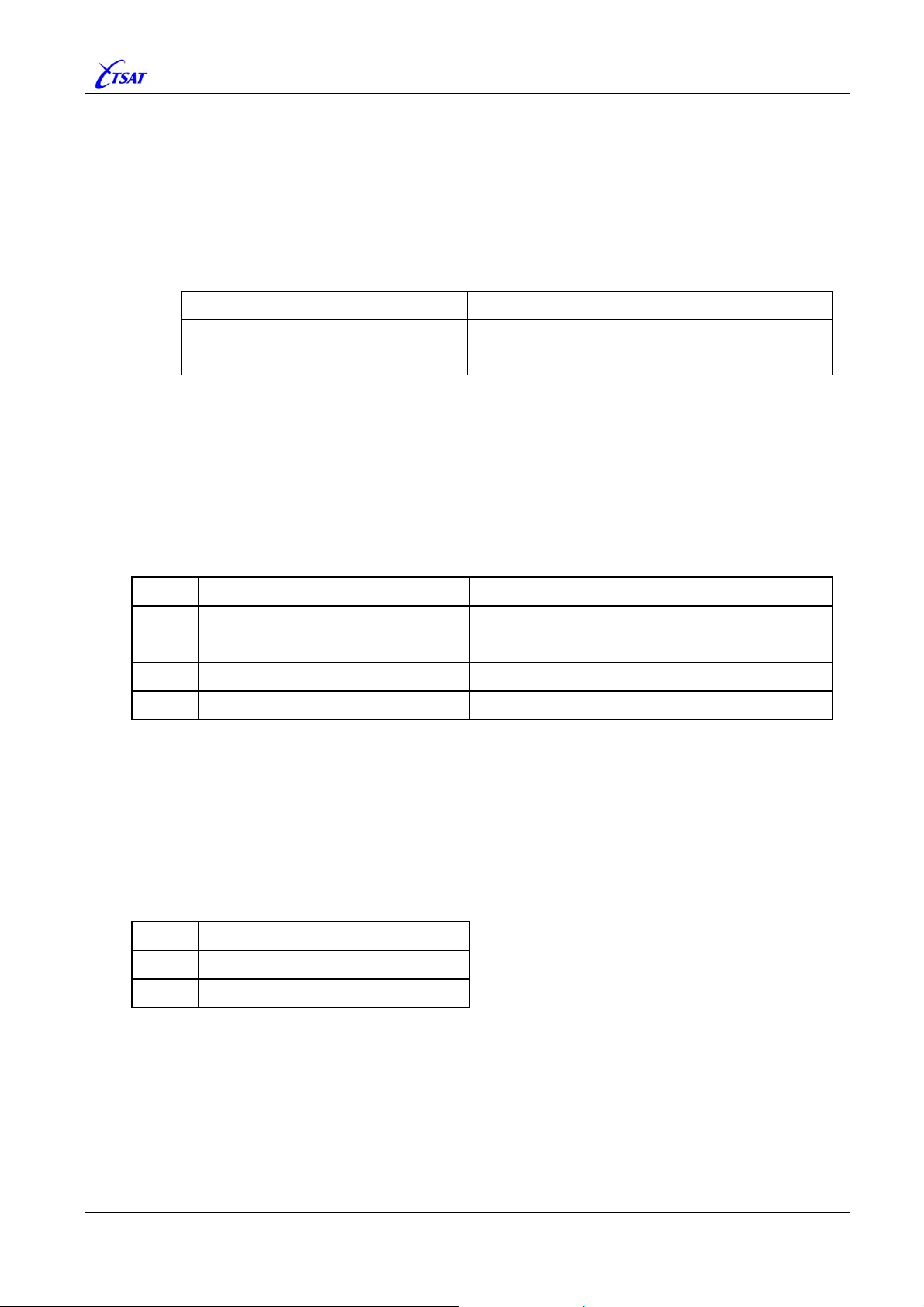
3.1.5 PORT_BIT_RATE [n]
Default 38400, Range 50…115200
Set Baud-Rate [bits / second].
• Not Used when PORT is connected to SOCKET or IP-STACK.
• Used when PORT is connected to Local-COM, or Remote-COM via “TSAT Comport Server”.
Note: Minimum Local-COM Baud-Rate is dependent on KERNEL version:
KERNEL version Minimum Baud-Rate
<= 3.2.1 – i.e. Release 3.4.0 300
>= 3.2.2 – i.e. Release 3.5.0 100
3.1.6 PORT_DATA_BITS [n]
Default 8, Range 5…8
Set Data-Bits [bits / character]
• Not Used when PORT is connected to SOCKET or IP-STACK.
• Used when PORT is connected to Local-COM, or Remote-COM via “TSAT Comport Server”.
Value Description Note
5 5 bits character Not supported by Local-COM
6 6 bits character Not supported by Local-COM
7 7 bits character
8 8 bits character
3.1.7 PORT_STOP_BITS [n]
Default 1, Range 1…2
Set Stop-Bits.
• Not Used when PORT is connected to SOCKET or IP-STACK.
• Used when PORT is connected to Local-COM, or Remote-COM via “TSAT Comport Server”.
Value Description
1 1 stop bit
2 2 stop bits
TSAT 3000 Configuration Parameter Description, January 2013 Page 15 of 124
Page 16

TSAT 3000 - Telemetry and data transfer via SATellite
3.1.8 PORT_PARITY [n]
Default 0, Range 0…2
Set Parity
• Not Used when PORT is connected to SOCKET or IP-STACK.
• Used when PORT is connected to Local-COM, or Remote-COM via “TSAT Comport Server”.
Value Description
0 NO parity
1 EVEN parity
2 ODD parity
3.1.9 PORT_FLOW_CTRL [n]
Default 0, Range 0…2
Set Flow-Control.
• Not Used when PORT is connected to SOCKET or IP-STACK.
• Used when PORT is connected to Local-COM, or Remote-COM via “TSAT Comport Server”.
Value Description Note
0 NO flow-control
1 HW flow-control (RTS / CTS)
2 SW flow-control (XON / XOFF)
See also LCC_TX_QUE_SIZE.
Data may be lost if any of the internal buffers
become full.
The COM-driver will set the RTS line when it is
prepared to receive data, and stop transmitting
data when the CTS signal is inactive.
For 7 bits ASCII transfer only. The COM-driver
should send the XOFF character when it is
busy and the XON character when it is
prepared to receive data. When the XON or
XOFF character is received, the COM-driver
should start or stop transmitting data.
NOTE: Not supported by Local-COM.
TSAT 3000 Configuration Parameter Description, January 2013 Page 16 of 124
Page 17
TSAT 3000 - Telemetry and data transfer via SATellite
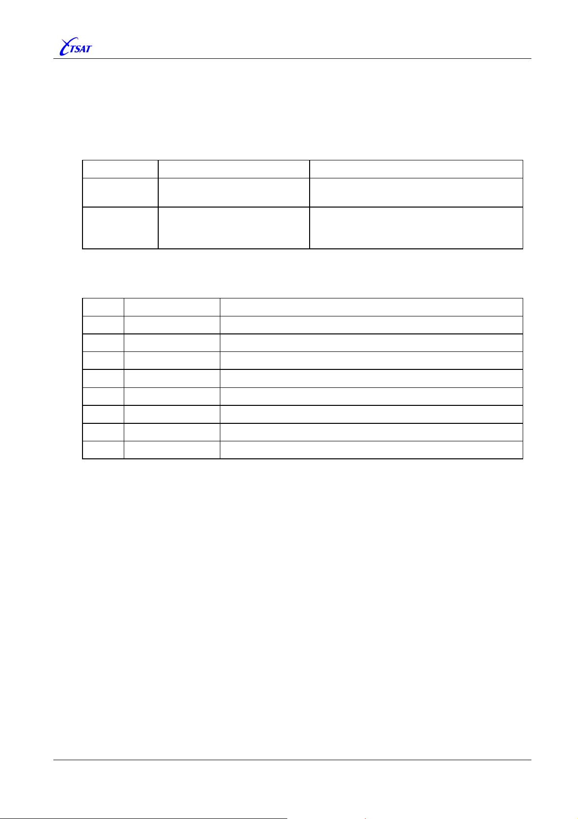
3.1.10 PORT_PRIORITY [n]
Default 3, Range 0…7
Set Priority of User-Data received from this PORT.
• Not Used when PORT_TYPE [n] is SERVICE.
In this case, the packets are assigned following priorities:
Packet Type Priority Note
Management-
Data
LCC_MANAGEMENT_PRIORITY
Some Management packet may be assigned
other priorities.
NMS will initiate and set LOW / HIGH priority:
User-Data <priority>
• LOW => Priority 3.
• HIGH => Priority 5.
• Used when PORT_TYPE [n] is STREAM, ADAPTER or NETWORK.
Received User-Data packet is assigned the
packet through the TSAT network, until it’s sent to a PORT.
Value Description Note
0 Very LOW priority
1
2
3 LOW priority
4
5 HIGH priority
6
7 Very HIGH priority Default LCC_MANAGEMENT_PRIORITY priority
LOW priority in NMS is mapped (by NMS) to Priority 3.
HIGH priority in NMS is mapped (by NMS) to Priority 5.
PORT_PRIORITY, and this priority will follow the
The packet-priority serves five purposes:
1) Packets will be entered in the Transmission-Queue[0…7], according to packet-priority. Higherpriority Transmission-Queues will be emptied for transfer to the satellite modem before Lowerpriority Transmission-Queues. See also
LCC_TX_QUE_SIZE.
2) When the total size of all Transmission-Queues (to satellite modem) is about to exceed the
threshold limit, the appropriate PORTs are flow controlled. See also
PORT_FLOW_CTRL [n].
LCC_TX_QUE_SIZE and
3) Packet priority is also used to restrict access to Inbound satellite link from RTs to HUB. See
MAC_SLOT_MAP_{0 | 1 | 2 | 3}.
4) The Port-TX-Queue (to COM or SOCKET) is priority-based when PORT_TYPE [n] is SERVICE.
In this case, Higher-priority packets will be sent to the Interface before Lower-priority packet.
See also
PORT_TX_QUEUE_SIZE [n].
5) The “Slot Request and Reservation (SRR) Facility” is reserving Inbound slots based on
packet-priority. See also
MAC_SLOT_REQ_RSV and MAC_SLOT_REQ_RSV_SOURCE.
See also PORT_OPTIONS [n].
TSAT 3000 Configuration Parameter Description, January 2013 Page 17 of 124
Page 18

TSAT 3000 - Telemetry and data transfer via SATellite
3.1.11 PORT_PKT_TIMEOUT [n]
Default 100, Range –1…5000
Set packet Timeout on this PORT, expressed in milliseconds.
Usage is dependent on
PORT_TYPE [n]
NONE n/a Not Used when PORT is Closed.
PORT_TYPE [n].
Value Description
NETWORK n/a
0 NO timeout. Received data will be forwarded immediately.
STREAM
1 … 5000
–1
0
SERVICE
ADAPTER
1 … 5000
–1
Not Used when PORT is connected to IP-STACK.
Packets received from IP-STACK will be forwarded immediately.
Timeout in ms.
A new timer will be started each time
received bytes will be forwarded when the last timer expires.
INFINITE timeout.
Actually, already received bytes will be forwarded 65535 ms after the
last byte is received.
NO timeout
If a complete protocol-packet is received, it will be forwarded
immediately. Otherwise, the received bytes (part of a protocol-packet)
will be discarded immediately.
Timeout in ms.
A timer will be started when the first
received, and if the complete protocol-packet hasn’t been received
when timer expire, already received bytes will be discarded.
INFINITE timeout.
Actually, already received bytes will be discarded after 65535 ms.
some bytes are received, and all
byte of a protocol-packet is
Note 1: When a
STREAM PORT is connected to Remote-COM via “TSAT Comport Server”, the
Timeout value is sent to, and handled by Remote-COM. Packets received from Remote-COM
will be forwarded immediately.
Note 2: Due to operating system timer ticks, the actual timeout is modulo 16.67 ms.
Timeout = 16.667 x INT( (60 x
PORT_PKT_TIMEOUT + 999) / 1000 ) – ( 0 to 16.667 ) ms.
Note 3: The Timeout parameter is one of 3 parameters that define when
STREAM data packets
should be forwarded to the satellite link. That is:
• PORT_PKT_TIMEOUT
PORT_FORWARD_CHAR [n]
•
PORT_MAX_PKT_SIZE [n]
•
Note 4:
timeout of 300
SERVICE PORT using a SOCKET connection, and Ver <= 30.3.0, are using a fixed
ms. This error is corrected in Ver >= 30.3.1.
TSAT 3000 Configuration Parameter Description, January 2013 Page 18 of 124
Page 19
TSAT 3000 - Telemetry and data transfer via SATellite
3.1.12 PORT_FORWARD_CHAR [n]
Default –1, Range –1…255 (0xFF)
Define the ASCII character that shall force an immediate sending of data (including the forward
character) from this
PORT_TYPE [n]
NONE
SERVICE
ADAPTER
NETWORK
STREAM PORT. Usage is dependent on PORT_TYPE [n].
Value Description
n/a Not Used
STREAM
–1 Forward character facility is disabled.
0 … 255 Forward character facility is enabled
.
Note: When a STREAM PORT is connected to Remote-COM via “TSAT Comport Server”, the
Forward-Char value is sent to, and handled by Remote-COM. Packets received from RemoteCOM will be forwarded immediately.
TSAT 3000 Configuration Parameter Description, January 2013 Page 19 of 124
Page 20
TSAT 3000 - Telemetry and data transfer via SATellite
3.1.13 PORT_MAX_PKT_SIZE [n]
Default 0, Range 0…15000
Define the maximum size of a packet received from a STREAM PORT.
Usage is dependent on
PORT_TYPE [n]
NONE
SERVICE
ADAPTER
NETWORK
PORT_TYPE [n].
Value Description
n/a Not Used
0
STREAM
1 … 15000
Define Max-Packet-Size to be exact equal DATA-SIZE. Forward packet
when this number of bytes has been received.
PORT MAX PKT SIZE less or equal DATA-SIZE:
Forward packet when this number of bytes has been received.
PORT MAX PKT SIZE larger than DATA-SIZE:
Forward data each time DATA-SIZE bytes has been received.
All Satellite-Link packets will be concatenated by the Packetizer at
remote side before complete packet is delivered to Application.
Note 1: When a STREAM PORT is connected to Remote-COM via “TSAT Comport Server”, the
Max-Packet-Size value is sent to, and handled by Remote-COM. Packets received from
Remote-COM will be forwarded when total received bytes exceeds
PORT_MAX_PKT_SIZE.
Note 2: DATA-SIZE is defined to be the maximum number of User-Data bytes available in a
Satellite-Link packet. I.e.
PKT_OUTBOUND_SIZE / PKT_INBOUND_SIZE – “TSAT Header”. The
size of “TSAT Header” can be from 5 to 15 bytes, depending on several MIB parameters:
• PKT_OUTBOUND_SIZE 1 or 2 bytes Data-Size.
•
PKT_INBOUND_SIZE 1 or 2 bytes Data-Size.
•
NET_RT_ADDRESS 1 or 2 bytes Address.
•
PORT_STREAM_RT [n] 2 or 3 extra bytes Second-Address + Port.
•
PORT_MAX_PKT_SIZE [n] 1 extra byte when Packetizer is used.
•
PORT_MAX_APPL_RETRIES [n] 1 to 4 extra bytes when Secure-Link is used.
•
LCC_WINDOW_SIZE 1 to 4 extra bytes when Secure-Link is used.
•
UTL_UTILITY_MASK UTILITY_NO_PIGGYBACK: 1 or 2 lesser bytes.
See also
PORT_PKT_TIMEOUT [n].
TSAT 3000 Configuration Parameter Description, January 2013 Page 20 of 124
Page 21

TSAT 3000 - Telemetry and data transfer via SATellite
3.1.14 PORT_TX_QUEUE_SIZE [n]
Default 2000, Range 1000…65535
Sets max number of bytes that may be (temporary) stored in the connected INTERFACE –
waiting for transmission to Application.
Data can be received from satellite link faster that the COM or SOCKET interface is able to send
them to Application. This can occur when:
• COM interface with small
• COM interface can be Hardware flow-controlled – See
• TCP SOCKETS may be flow-controlled be remote peer.
In this case, newly arrived data will be discarded when total number of bytes in Interface-SendQueue exceeds the defined limit.
Usage is dependent on PORT_TYPE [n].
PORT_TYPE [n]
NONE n/a Not Used when PORT is Closed.
NETWORK n/a Not Used when PORT is connected to IP-STACK.
STREAM
ADAPTER
Value Description
<bytes
>
PORT_BIT_RATE [n].
PORT_FLOW_CTRL [n].
Max number of bytes that may be stored in COM or SOCKET Interface
Send-Queue – waiting for transmission to Application.
Date will be discarded when total number of bytes in Send-Queue exceeds
PORT_TX_QUEUE_SIZE. Priority based Send-Queue may optionally be
enabled by bit 3 (0x08 –
PRIORITY_TX_QUEUE) in PORT_OPTIONS [n].
SERVICE
<bytes
>
Max number of bytes that may be stored (for each priority) in COM or
SOCKET Interface Send-Queue – waiting for transmission to Application.
Date will be discarded when total number of bytes in Send-Queue exceeds
PORT_TX_QUEUE_SIZE x (Packet-Priority + 1).
See also
PORT_PRIORITY [n] and LCC_MANAGEMENT_PRIORITY.
TSAT 3000 Configuration Parameter Description, January 2013 Page 21 of 124
Page 22

TSAT 3000 - Telemetry and data transfer via SATellite
3.1.15 PORT_REPLY_TIMEOUT [n]
Default 0, Range 0…60
Ver <= 31.3.0:
Not Implemented.
Ver >= 31.4.0:
The “Reply Timeout” facility is controlled by this MIB parameter, and is enabled for
ports when this value is different to zero.
In this case, a timer is started (i.e.
to
the PORT (from TSAT modem to locally connected equipment).
Data from
satellite link to the HUB. Data received after
the PORT will only be accepted as long as this timer is running, and sent via
PORT_REPLY_TIMEOUT [seconds]) each time data is sent
the timer has expired will be discarded.
When bit 23 (0x80.000 – DEBUG_APPLICATION) in UTL_DEBUG_MASK is enabled, a Message
will be issued whenever data is discarded.
This facility will correct a problem that could occur at an RT with double (alternate)
communication to Application-Equipment (AE). When the other communication path is much
faster than TSAT, the AE could be polled more often and would also reply more often. When
reply is feed to both
communication paths, TSAT RT would sent all these replies to HUB and
possible saturate the inbound link. Enabling this facility will correct this malfunction.
Usage is dependent on
PORT_TYPE [n]
PORT_TYPE [n].
Value Description
STREAM
NONE
SERVICE
ADAPTER
NETWORK
STREAM
n/a Not Used
0 “Reply Timeout” facility is disabled – Normal operation.
1 … 60
“Reply Timeout” facility is enabled as described above.
TSAT 3000 Configuration Parameter Description, January 2013 Page 22 of 124
Page 23
TSAT 3000 - Telemetry and data transfer via SATellite
3.1.16 PORT_SWITCH_TIMEOUT [n]
Default 0, Range 0…3600
Ver <= 31.7.1:
Not Implemented.
HUB Ver >= 31.8.0
Not Used
RT Ver >= 31.8.0
The “Switch Timeout” facility is controlled by this MIB parameter, and is enabled for
ADAPTER and NETWORK ports when this value is different to zero, and the RT is part of a
Redundant satellite network (i.e.
In this case, a timer is started (i.e.
to
the PORT (from TSAT modem to locally connected equipment).
RT will switch to the other HUB (Main- or Backup-HUB) when timer expires.
PHL_TX_HUB_FREQUENCY_BKUP is different to zero).
PORT_SWITCH_TIMEOUT [seconds]) each time data is sent
This facility will correct a problem that could occur when the Application (at HUB side) only
have access to Application-Equipment (at RT side) via one
of the HUBs in a Redundant
satellite network. This malfunction could have been caused by routing problems, or general
equipment failure, at the HUB side(s).
Enabling this facility will cause the RT to switch between Main- and Backup-HUB until
Application communication is working ok.
Usage is dependent on
PORT_TYPE [n]
PORT_TYPE [n].
Value Description
STREAM,
See also
NONE
SERVICE
ADAPTER
NETWORK
PHL_SWITCH_BACK_TO_MAIN_HUB
PHL_SWITCH_SLAVE_HUB_TIMEOUT
n/a Not Used
0 “Switch Timeout” facility is disabled – Normal operation. STREAM
1 … 3600
“Switch Timeout” facility is enabled as described above.
TSAT 3000 Configuration Parameter Description, January 2013 Page 23 of 124
Page 24
TSAT 3000 - Telemetry and data transfer via SATellite
3.1.17 PORT_OPTIONS [n]
Default 0, Range 0…255 (0xFF)
Bit field to control miscellaneous PORT options.
Bit Mask Mnemonic Description Version
0
0x01
n/a
1
2
3
4
5
6
7
0x02
0x04
0x08
0x10
0x20
0x40
0x80
PRIORITY_FIXED
PRIORITY_TX_QUEUE
DEBUG_PRINT_RX
DEBUG_PRINT_TX
LOOP
n/a
Disable dynamic priority allocation. >= 31.8.0
Enable Priority Send-Queue mechanisms.
Print (to Console) all packets received from PORT.
Print (to Console) all packets sent to PORT.
n/a
Loop all data sent and received to/from PORT.
PRIORITY FIXED – Ver >= 31.8.0
Apply only to the Network-PORT – Normally
PORT_OPTIONS [ 3 ].
Normally, IP packets from the IP-Stack with “precedence” (in “Type-of-Service” field) >= 5 (i.e.
RTP packets) will be assigned HIGH priority (value 5) in Ver >= 31.8.0 (Release >= R4.7.0),
while all other IP packets will be assigned the priority defined by
PRIORITY_FIXED will disable this behaviour, and assign the same priority to all IP packets.
PORT_PRIORITY [n].
PRIORITY TX QUEUE
Normally, data to be stored in Interface Send-Queue will be discarded when total number of
already stored bytes exceeds the limit defined by
STREAM and ADAPTER PORTs, because all packets to such PORTs will normally have the same
PORT_TX_QUEUE_SIZE [n]. This works OK for
packet-priority.
However, packets sent to a
by
PORT_PRIORITY [n] and LCC_MANAGEMENT_PRIORITY), and we want to give more priority to
high-priority-packets. Therefore, data to
number of already stored bytes exceeds
SERVICE PORT will normally have different packet-priority (defined
SERVICE PORTS will be discarded when the total
PORT_TX_QUEUE_SIZE [n] x (Packet-Priority + 1).
The PRIORITY_TX_QUEUE option will enable this Priority-based Send-Queue mechanism for
STREAM and
ADAPTER PORTs as well. It might be necessary to do this if you want to give
different priority to some of the RTs in a Leased-Line (GROUP or BROADCAST).
DEBUG PRINT {RX | TX}
Print all packets received and/or sent from/to PORT to Console.
TSAT 3000 Configuration Parameter Description, January 2013 Page 24 of 124
Page 25
TSAT 3000 - Telemetry and data transfer via SATellite
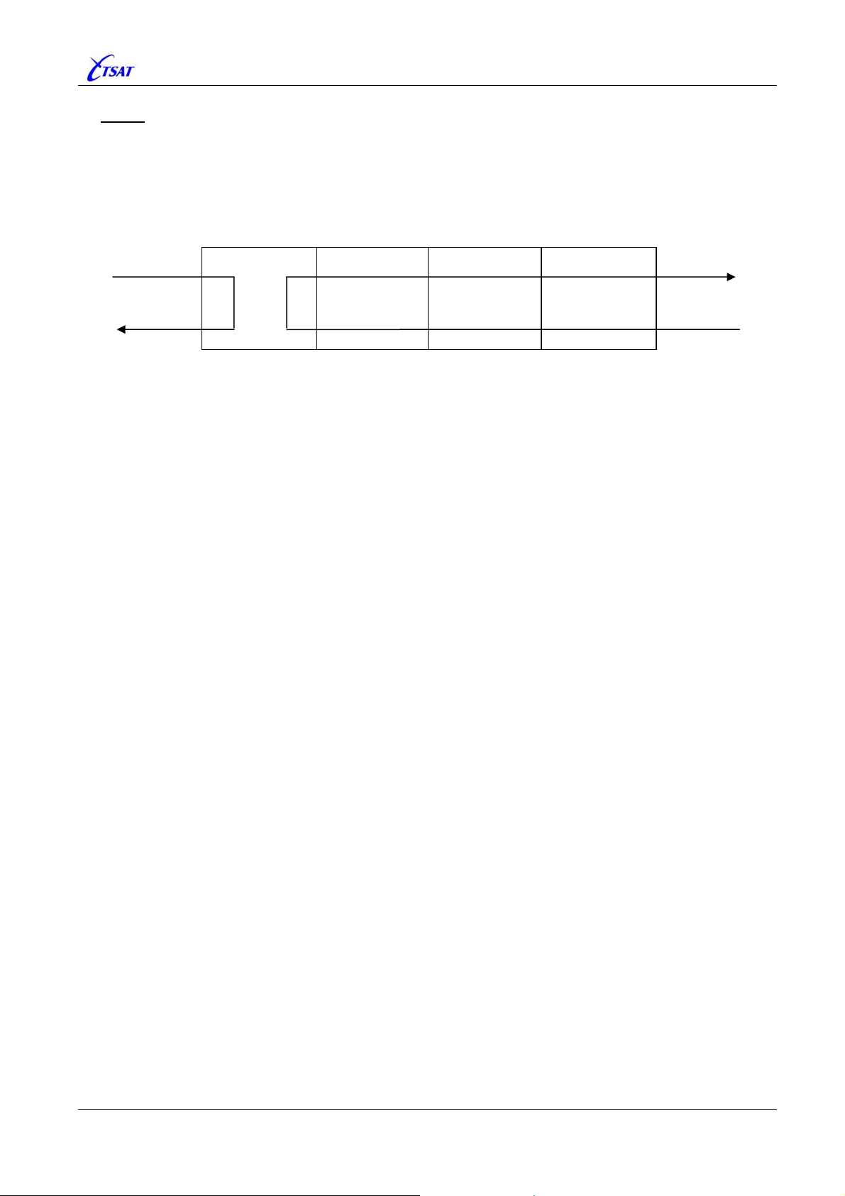
LOOP
When enabled, data received from the satellite link and sent to PORT, will be (software) looped
within the PORT module, and handled as it was received from the INTERFACE (i.e. sent back to
satellite link and the other (remote) network node).
Data received from the INTERFACE will be looped back to the INTERFACE.
PORT INTERFACE Driver Physical Device
Satellite
Link
Ethernet
or RS 232
TSAT 3000 Configuration Parameter Description, January 2013 Page 25 of 124
Page 26
TSAT 3000 - Telemetry and data transfer via SATellite
3.1.18 PORT_STREAM_RT [n]
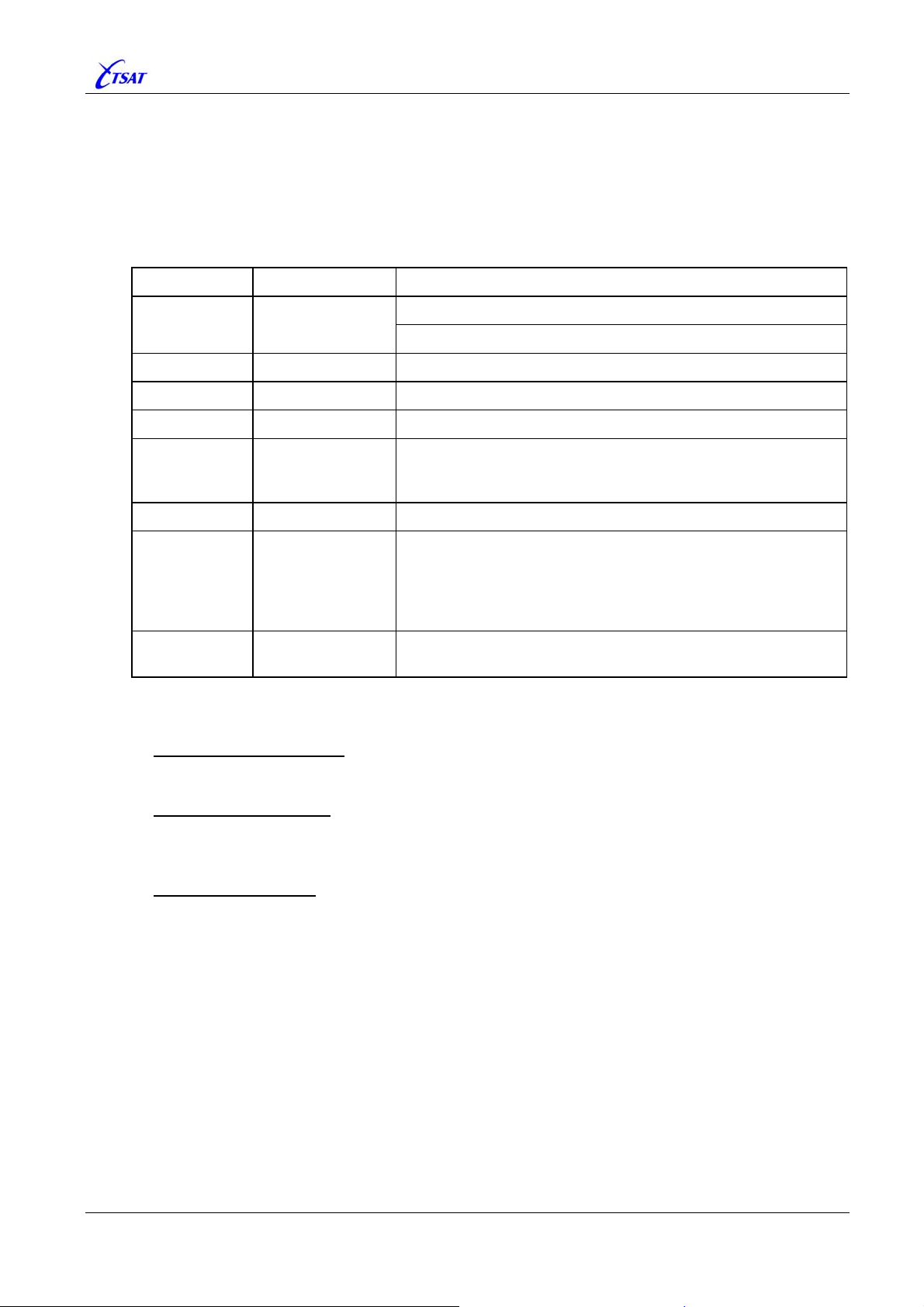
Default –1, Range –1…12287 (0x2FFF)
• Not Used when PORT_TYPE [n] is SERVICE.
In this case, RT-Address is included in received packets from NMS.
• Used when
All User-Data received from this PORT will be sent to the indicated Unit(s).
Value Hex Description
PORT_TYPE [n] is STREAM, ADAPTER or NETWORK.
–1 0xFFFF.FFFF
0 0x0000 BROADCAST – I.e. ALL RTs.
1 … 4095 0x0001 … 0x0FFF RT 1 … RT 4095.
4096 0x1000 n/a – CLUSTER 0 isn’t defined.
4097 …8191 0x1001 … 0x1FFF
8192 0x2000 n/a – GROUP 0 isn’t defined.
8193 … 8292 0x2001 … 0x2064
8293 … 12287 0x2065 … 0x2FFF
HUB .
IP Routed Line in HUB Ver >= 30.4.0
CLUSTER Address 1 … 4095.
That is all RTs with NET_FIRST_POLL_RT equal lower 12 bits
(0x0FFF) of
GROUP Address 1 … 100.
That is all RTs that are member of the GROUP defined by the
lower 12 bits (0x0FFF) of
An RT can be member of max 5 GROUPs.
Membership is defined by
GROUP Address 101 … 4095.
n/a – Highest GROUP Address is 100.
PORT_STREAM_RT.
PORT_STREAM_RT.
NET_GROUPS [1…5].
Use
PORT_STREAM_RT and PORT_STREAM_RT_PORT [n] to define Leased Lines:
• HUB Ù RT Leased Line
See next page.
• RT Ù RT Leased Line
RT:
PORT_STREAM_RT = RT, BROADCAST, GROUP or CLUSTER.
PORT_STREAM_RT_PORT = PORT(s) at remote RT.
• LOCAL Leased Line
HUB:
PORT_STREAM_RT = HUB.
PORT_STREAM_RT_PORT = PORT(s) at local HUB.
RT: PORT_STREAM_RT = NET_RT_ADDRESS.
PORT_STREAM_RT_PORT = PORT(s) at local RT.
Note: Just for fun, it’s possible to route User-Data from one PORT to other PORT(s) within
the same local Unit. Why should you do this?
TSAT 3000 Configuration Parameter Description, January 2013 Page 26 of 124
Page 27

TSAT 3000 - Telemetry and data transfer via SATellite
• HUB Ù RT Leased Line
HUB:
PORT_STREAM_RT = RT, BROADCAST, GROUP or CLUSTER.
PORT_STREAM_RT_PORT = PORT(s) at RT.
RT: PORT_STREAM_RT = HUB.
PORT_STREAM_RT_PORT = Don’t care.
Ver <= 30.1.1: Leased Line to GROUP or CLUSTER doesn’t work correctly. USER_DATA
will be sent from HUB to the indicated GROUP or CLUSTER, but USER_DATA from
RTs will not
NMS).
be sent back to this PORT. They will be sent to all SERVICE PORTs (i.e.
Ver >= 30.2.0: All RTs will signal GROUP membership (i.e. NET_GROUPS [1…5]) and
CLUSTER address (i.e.
NET_FIRST_POLL_RT) back to HUB in POLL_ACK packets.
HUB will save this information and use it to decide to which PORT data from RT
shall be transmitted (based on RT address and
PORT_STREAM_RT [n]).
You can see when this information is changed on the HUB by enable bit 27
(0x0800.0000 –
DEBUG_ADDR) in UTL_DEBUG_MASK.
Note 1: Minimum PKT_INBOUND_SIZE is increased from 16 to 24 bytes, because
size of
POLL_ACK packet is increased.
Note 2: In large networks, it could take long time from RT is configured with GROUP
membership until this information is signalled back to HUB.
returned to HUB when RT is polled (HUB is requesting RT in
it doesn’t have any
with POLL_ACK if they always
reply with
POLL_ACK at least each 10
USER_DATA to send. RTs Ver <= 30.1.1 would never reply
had USER_DATA to send. RTs Ver >= 30.2.0 will
th
time it’s polled.
POLL_ACK packet is
SYNC packet), and
Example: 100 RTs, 16 Slots-in-Frame, 64 kbps, 100 bytes (Slot 13.6 ms).
Max Time: 13.6 x (16+1) x 100 x 10 = 231200 ms = 3 min 51 sec.
Normal Average: 13.6 x (16+1) x 50 = 11560 ms = 12 sec.
• HUB Ù RT – IP Routed Line
PORT_STREAM_RT value –1 will have different interpretation on the HUB, depending on
Version and
PORT_TYPE [n]:
HUB Ver <= 30.3.1 or PORT_TYPE <> NETWORK.
Local Leased Line
– Loop data within the HUB Main-Unit.
HUB Ver >= 30.4.0 and PORT_TYPE = NETWORK.
IP Routed Line
– Send IP-packet directly to the RT indicated by the IP-packet’s
destination MAC-Address. The MAC-Address is actually the 16 lower bits of RT’s
IP_ADDRESS_SAT
signal its own MAC address back to HUB in
, and HUB know about these addresses since RT Ver >= 30.4.0 will
POLL_ACK packets. If HUB for some reason
doesn’t know the RT’s MAC-Address (I.e. RT Ver <= 30.3.1), the IP-packet will be
BROADCAST to all RTs.
When “IP Routed Line” is enabled, it’s also possible to enable the “Secure Link Facility”
for Outbound
IP-packets. See PORT_MAX_APPL_RETRIES [n].
Note 1: Minimum PKT_INBOUND_SIZE is increased from 24 to 26 bytes, because size of
POLL_ACK packet is increased.
Note 2: In large networks … (see Note 2 in section above).
TSAT 3000 Configuration Parameter Description, January 2013 Page 27 of 124
Page 28
TSAT 3000 - Telemetry and data transfer via SATellite
3.1.19 PORT_STREAM_RT_PORT [n]
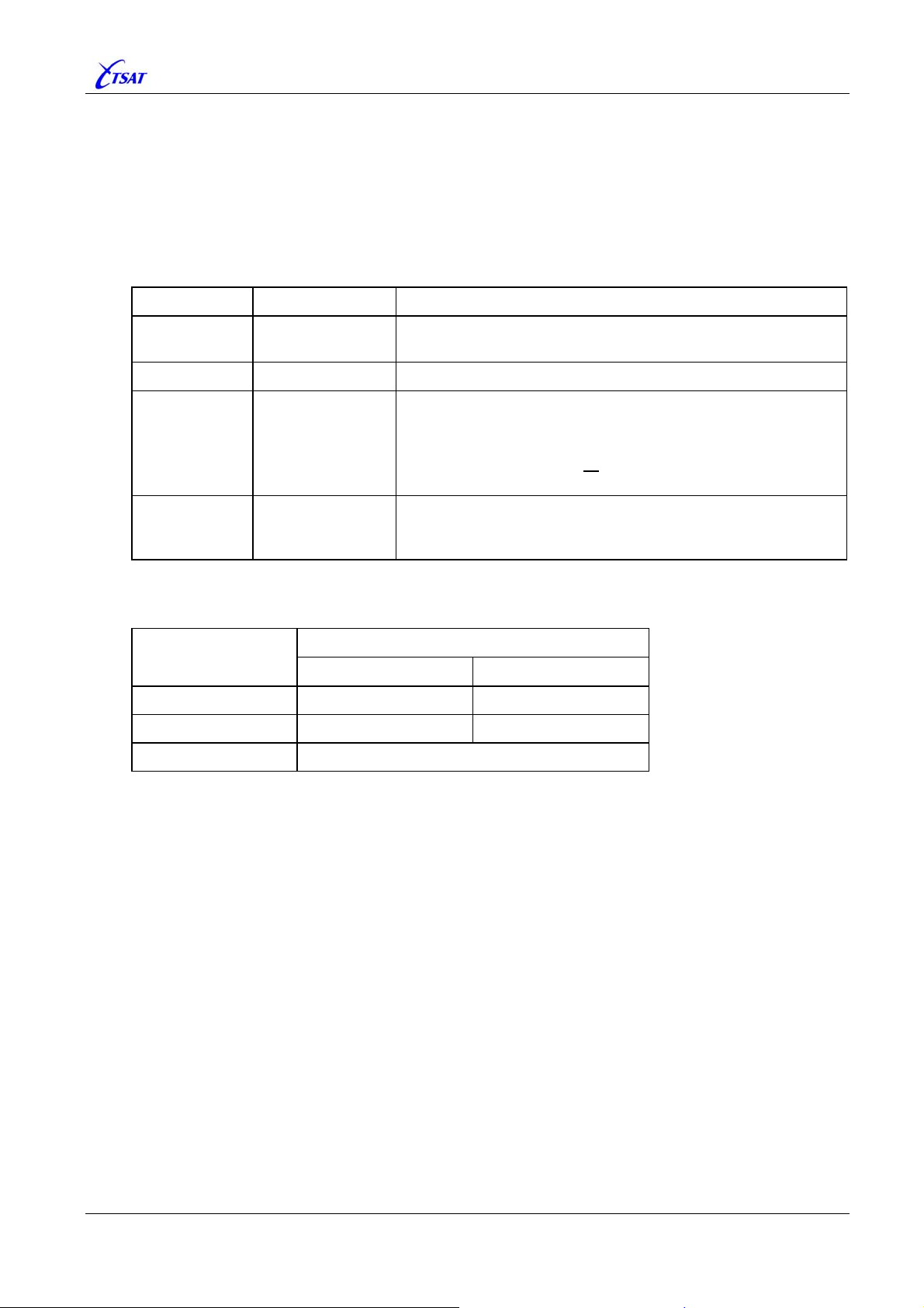
Default 1, Range 1…255
• Not Used when PORT_TYPE [n] is SERVICE.
In this case, RT-Port is included in received packets from NMS.
• Used when
All User-Data received from this PORT will be sent to the Unit(s) defined by
PORT_STREAM_RT [n], and Port(s) as defined below:
Value Hex Description
PORT_TYPE [n] is STREAM, ADAPTER or NETWORK.
1 … 64 0x01 … 0x40
65 … 127 0x41 … 0x7F n/a – Reserved for internal addressing.
128 … 254 0x80 … 0xFE
255 0xFF
Normally, this parameter isn’t used at RT.
Usage is dependent on
PORT_STREAM_RT
Leased Line
HUB to RT PORT(s) at remote RT
RT to RT n/a PORT(s) at remote RT
LOCAL
PORT_STREAM_RT [n], as shown in table below:
PORT_STREAM_RT_PORT
HUB RT
PORT(s) at Local Unit
PORT 1 … 64.
User-Data is sent to the (remote) PORT.
BITMASK.
User-Data is sent to one or more (remote) PORTs 1 … 7,
defined by the bitmask of 7 lower bits (0x7F).
Note: You cannot send to all
7 PORTs, because this will give
the bitmask 0xFF, which is the MANAGEMENT Port.
MANAGEMENT.
User-Data is sent to (remote) Management-module, which will
loop data back to originator.
Don’t care
TSAT 3000 Configuration Parameter Description, January 2013 Page 28 of 124
Page 29

TSAT 3000 - Telemetry and data transfer via SATellite
3.1.20 PORT_MAX_APPL_RETRIES [n]
Default 0, Range 0…64
The “Secure Link Facility” is enabled (for all data received from this PORT) by setting
PORT_MAX_APPL_RETRIES greater than zero. This sets the maximum number of attempts to
retransmit an
Group addressing from HUB to RT) packets will never
APPLICATION layer (with User-Data) packet. Multi destination (Broadcast and
be retransmitted.
The “Secure Link Facility” is always enabled for most of the NETWORK layer (with ManagementData) packets. Maximum number of attempts to retransmit a NETWORK layer packet is
hardcoded to 5.
When the packet has been retransmitted this number of times, the link is assumed to be DOWN,
and the HUB and RT will take a pause, trying to reopen the link with the exchange of
LINK_RESET / LINK_ACK packets (See LCC_MAX_LINK_RETRIES and LCC_{MIN |
MAX}_RESET_RETRANS_DELAY
). The packet will then be retransmitted when the link has been
re-opened.
• Retransmission timeout is defined by the range LCC_{MIN | MAX}_RETRANS_DELAY.
• Packet lifetime is defined by
• Max number of outstanding packets waiting for acknowledges is defined by
and
LCC_RETRANS_QUE_SIZE.
LCC_MAX_{APPL | MNGT}_PKT_AGE.
LCC_WINDOW_SIZE
3.1.21 PORT_TX_FREQUENCY_2 [n]
Default 0, Range 0…1
HUB:
Not Used.
RT Ver <= 30.7.0:
Not Used.
Note: The value must
be zero for correct RT operation.
RT Ver >= 30.8.0:
Used by RT in Multi-Inbound-Link (MIL) networks. See
PHL_TX_RT_FREQUENCY_2. When
enabled, all Application-Data received from this PORT will be sent to the Slave-HUB, using
the Secondary Inbound carrier.
TSAT 3000 Configuration Parameter Description, January 2013 Page 29 of 124
Page 30
TSAT 3000 - Telemetry and data transfer via SATellite
3.2 SOCKET PARAMETERS
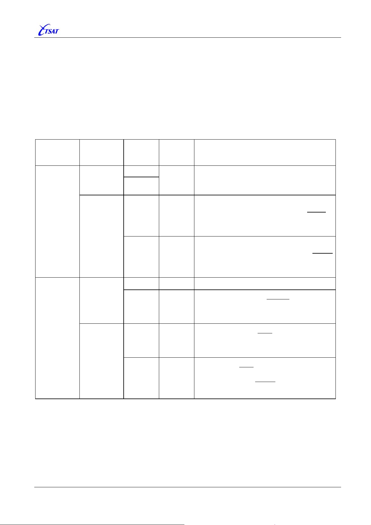
Define SOCKETs used for communication to/from this Main-Unit.
The type of data on this SOCKET is defined by
•
SOCK_TYPE [n]
… while Transport-Protocol and type of SOCKET is defined by:
SOCK_PROTOCOL [n]
•
•
SOCK_ADDRESS [n]
•
SOCK_LOCAL_PORT [n]
•
SOCK_REMOTE_PORT [n]
… as shown in table below:
SOCK_
PROTOCOL
SOCK_
ADDRESS
SOCK_
LOCAL_
PORT
SOCK_
REMOTE_
PORT
Description
TCP
UDP
or
“LISTEN”
<ADDRESS>
<empty>
or
“LISTEN”
<ADDRESS>
0 <empty>
n/a
1 … 65535
0 0 … 65535
1 … 65535 0 … 65535
0 n/a
1 … 65535 n/a
0 0 … 65535
1 … 65535 0 … 65535
TCP Server Socket. Wait for an incoming
connection to this <
LOCAL-PORT>.
TCP Client Socket. Establish a connection to
ADDRESS>:<REMOTE-PORT>, using a default
<
LOCAL-PORT> selected by IP-STACK.
<
A new attempt to establish connection is done
SOCK_CONNECT_TIMEOUT [n] second.
each
TCP Client Socket. Establish a connection to
ADDRESS>:<REMOTE-PORT>, using the defined
<
LOCAL-PORT>.
<
A new attempt to establish connection is done
SOCK_CONNECT_TIMEOUT [n] second.
each
Not Applicable.
UDP Receive Socket. Receive UDP packets
to this <
any
You cannot send any data to this SOCKET.
LOCAL-PORT> from any ADDRESS, and
REMOTE-PORT.
UDP Send Socket. Send UDP packets to
ADDRESS>:<REMOTE-PORT>, using a default
<
LOCAL-PORT> selected by IP-STACK.
<
You cannot receive any data from this SOCKET.
UDP Socket. Send UDP packets to
ADDRESS>:<REMOTE-PORT>, using the defined
<
LOCAL-PORT>, and receive UDP packets from
<
the same <
defined <
ADDRESS>:<REMOTE-PORT> to the
LOCAL-PORT>.
TSAT 3000 Configuration Parameter Description, January 2013 Page 30 of 124
Page 31
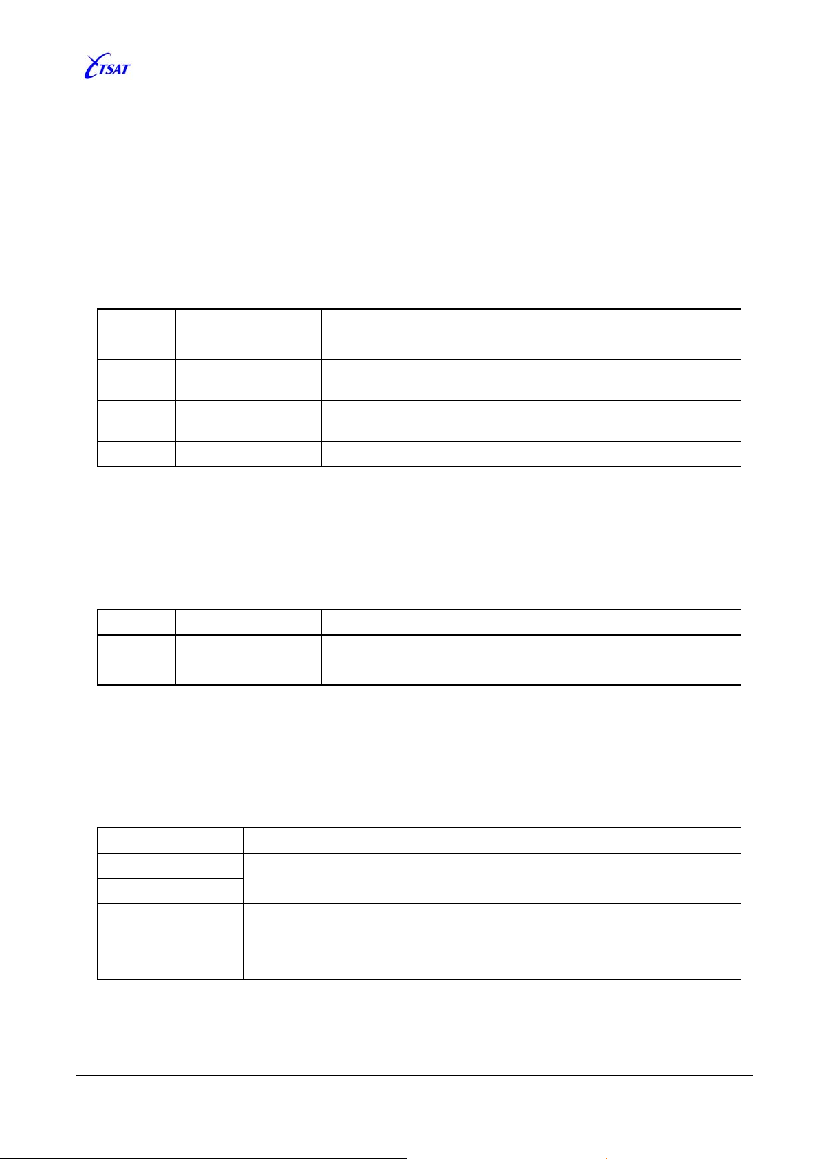
TSAT 3000 - Telemetry and data transfer via SATellite
3.2.1 SOCK_MAX_SOCKETS
Default 4, Range 1…32
Set number of SOCKETs.
3.2.2 SOCK_TYPE [n]
Default 0, Range 0…3
Set Type of data on this SOCKET.
Value Mnemonic Description
0 NONE Closed.
1 RAW_DATA
2 TSAT_NMS
Raw byte stream data. The input bytes are transferred
transparently to the connected PORT.
TSAT Socket protocol. Connected to NMS.
HUB Ver >= 30.4.0: Also connect to other HUBs.
3 COMPORT_SERVER TSAT Socket protocol. Connected to “TSAT Comport Server”
3.2.3 SOCK_PROTOCOL [n]
Default 0, Range 0…1
Set Transport-Protocol for this SOCKET.
Value Mnemonic Description
0 TCP Transmission Control Protocol
1 UDP User Datagram Protocol
3.2.4 SOCK_ADDRESS [n]
Default “LISTEN”
Set ADDRESS associated with this SOCKET.
Value Description
<empty>
“LISTEN”
• Set TCP Server Socket. Wait form incoming TCP connection.
• Set UDP Receive Socket. Wait for received UDP packets.
Define ADDRESS to which this
<ADDRESS>
• TCP Client Socket should make a connection, and then send/receive data.
• UDP Send Socket should receive data,
• UDP Socket should receive and send data,
TSAT 3000 Configuration Parameter Description, January 2013 Page 31 of 124
Page 32
TSAT 3000 - Telemetry and data transfer via SATellite
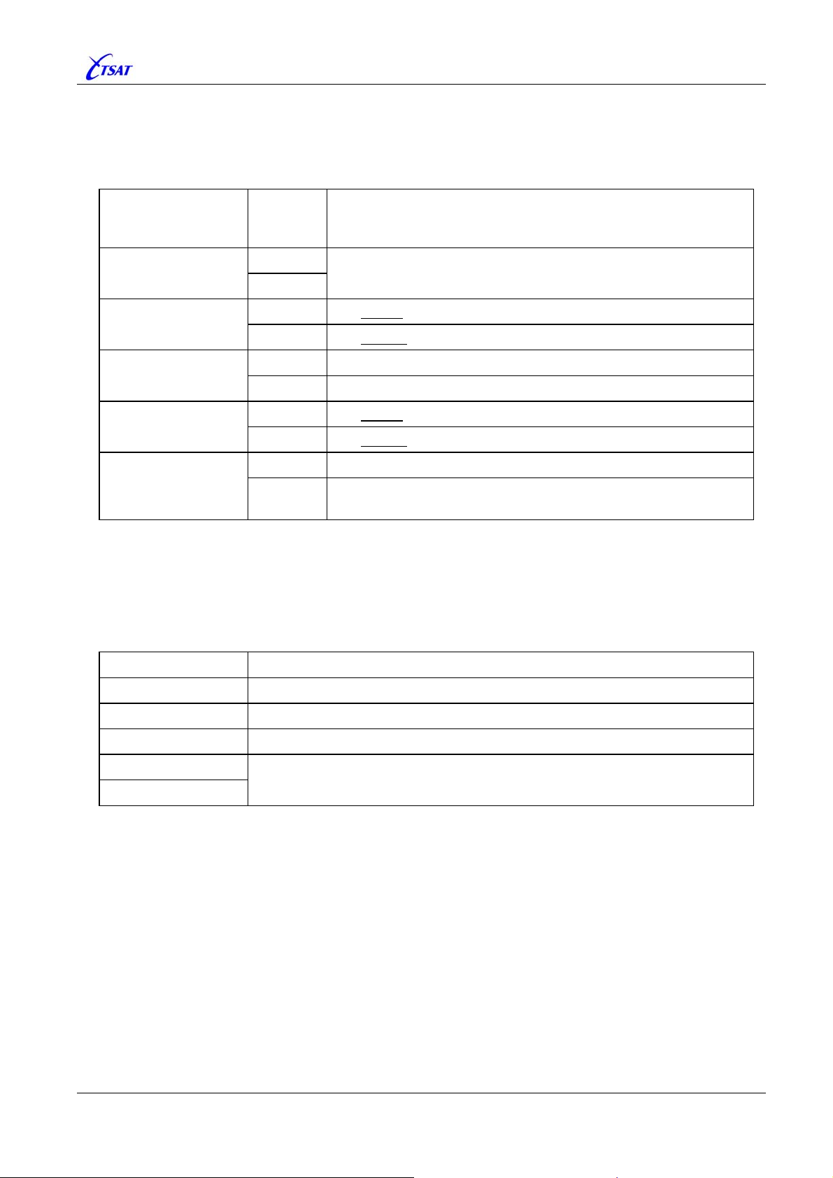
3.2.5 SOCK_LOCAL_PORT [n]
Default 4000, Range 0…65535
Set LOCAL-PORT associated with this SOCKET.
SOCK_
Type of Socket
LOCAL_
PORT
Description
TCP Server Socket
Wait for incoming connection to this <LOCAL-PORT>.
1 … 65535
0 Use default <LOCAL-PORT> selected by IP-STACK.
TCP Client Socket
1 … 65535 Use defined
0 n/a
UDP Receive Socket
1 … 65535 Receive UPD packets to this <
0 Use default <LOCAL-PORT> selected by IP-STACK.
UDP Send Socket
1 … 65535 Use defined
0 n/a
0
UDP Socket
1 … 65535
Receive UPD packets to this <
use the same <
3.2.6 SOCK_REMOTE_PORT [n]
Default 0, Range 0…65535
Set REMOTE-PORT associated with this SOCKET.
Type of Socket Description
<LOCAL-PORT> when connecting to remote peer.
LOCAL-PORT>.
<LOCAL-PORT> when sending to remote.
LOCAL-PORT>, and
LOCAL-PORT> when sending to remote.
TCP Server Socket n/a
TCP Client Socket Establish connection to <REMOTE-PORT>.
UDP Receive Socket n/a
UDP Send Socket
Send UDP packets to <
REMOTE-PORT>.
UDP Socket
TSAT 3000 Configuration Parameter Description, January 2013 Page 32 of 124
Page 33
TSAT 3000 - Telemetry and data transfer via SATellite
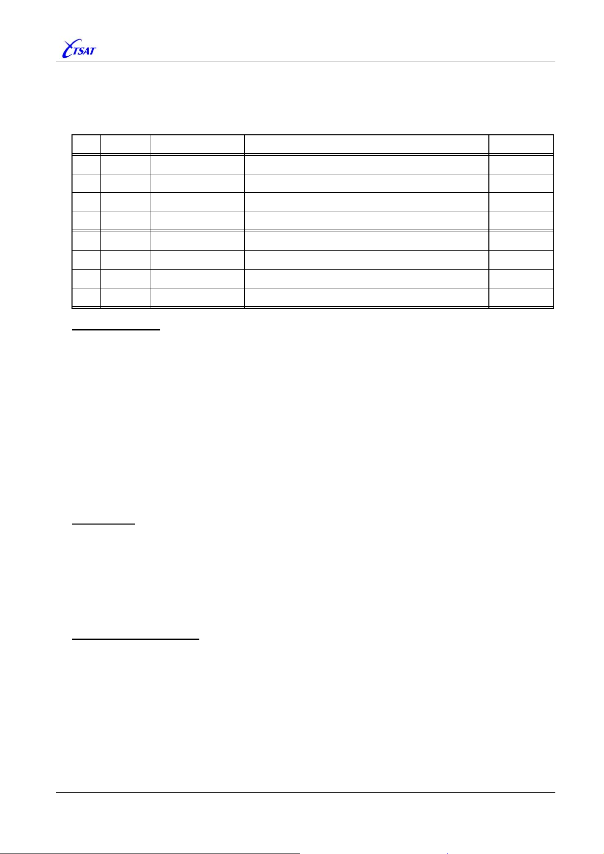
3.2.7 SOCK_OPTIONS [n]
Default 0, Range 0…255 (0xFF)
Bit field to control miscellaneous SOCKET options.
Bit Mask Mnemonic Description Version
0
0x01
TCP_KEEPALIVE
Detect dead TCP connections.
1
2
3
4
5
6
7
0x02
0x04
0x08
0x10
0x20
0x40
0x80
TCP_DELAY
DEBUG_PRINT_RX
DEBUG_PRINT_TX
LOOP
Delay and merge small TCP segments.
n/a
n/a
Print (to Console) all bytes received from SOCKET.
Print (to Console) all bytes sent to SOCKET.
>= 30.4.0
>= 30.4.0
n/a
Loop all data sent and received to/from SOCKET.
TCP KEEPALIVE
Enable this option to make the transport protocol (TCP) initiate a timer to detect a dead
connection. This prevents an application from hanging on an invalid connection. The integrity of a
connection is verified by transmitting zero-length TCP segments triggered by a timer, to force a
response from a peer node. If the peer does not respond after repeated transmissions of the
KEEPALIVE segments, the connection is dropped, all protocol data structures are reclaimed, and
processes sleeping on the connection are awakened.
• Applicable when
• There’s no reason to enable this feature when
COMPORT_SERVER, because TSAT Socket-Protocols will always exchange data to detect
SOCK_PROTOCOL [n] is TCP, only.
SOCK_TYPE [n] is TSAT_NMS or
dead connections.
• There’s also no reason to enable this feature when
SOCK_TYPE [n] is RAW_DATA and you
know that connected application always will send data at regular intervals. In this case, the
SOCK_IDLE_TIMEOUT [n] could be used to detect dead TCP and UDP connections.
TCP DELAY
Applicable when
SOCK_PROTOCOL [n] is TCP, only. By default, all TCP packets will be sent to
the peer node immediately. You can enable this option to avoid the congestion that can be
produced by a large number of small TCP segments. The TCP_DELAY algorithm attempts to
have no more than one outstanding unacknowledged segment in the transmission channel while
queuing up the rest of the smaller segments for later transmission. Another segment is sent only
if enough new data is available to make up a maximum sized segment, or if the outstanding data
is acknowledged.
DEBUG PRINT {RX | TX}
Ver <= 30.3.1
Not Implemented.
Ver >= 30.4.0
Print all data received and/or sent from/to SOCKET to Console.
TSAT 3000 Configuration Parameter Description, January 2013 Page 33 of 124
Page 34
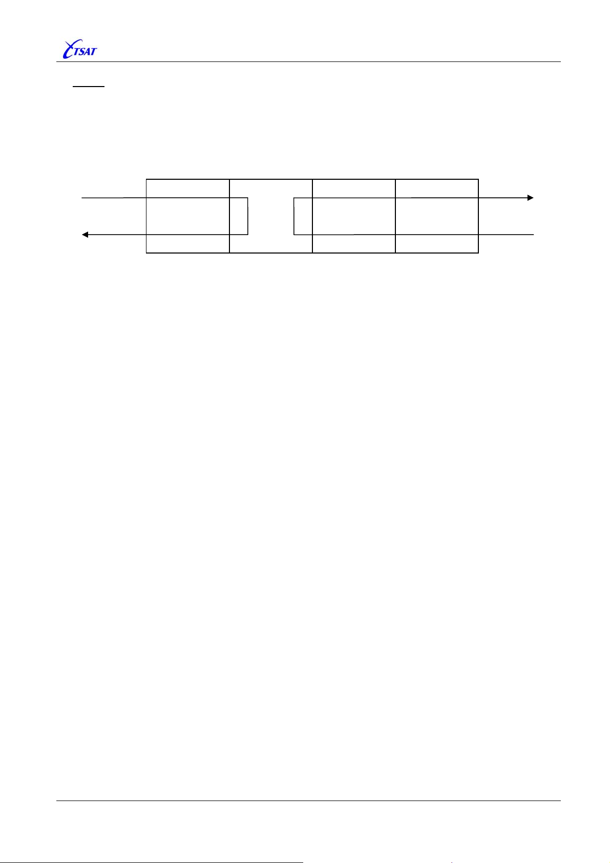
TSAT 3000 - Telemetry and data transfer via SATellite
LOOP
When enabled, data received from the satellite link and sent to SOCKET, will be (software)
looped within the SOCKET module, and handled as it was received from the IP-STACK (i.e. sent
back to PORT and the other (remote) network node).
Data received from the IP-STACK will be looped back to the IP-STACK.
PORT SOCKET IP-STACK Physical Device
Satellite
Link
Ethernet
TSAT 3000 Configuration Parameter Description, January 2013 Page 34 of 124
Page 35
TSAT 3000 - Telemetry and data transfer via SATellite
3.2.8 SOCK_IDLE_TIMEOUT [n]
Default 10, Range 0…3600
Set the Idle-Timeout (in seconds).
Value Description
0 NO Timeout.
Idle Timeout in seconds.
A timer will be re-started each time data is received from the SOCKET.
The SOCKET will be Closed when timer expires, and depending on Type of Socket:
Type of Socket Description
1 … 3600
TCP Server Socket Start to wait for new connecting from remote peer.
TCP Client Socket
UDP Receive Socket
Wait 1 second, and Open SOCKET once again.
UDP Send Socket
UDP Socket
3.2.9 SOCK_CONNECT_TIMEOUT [n]
Default 10, Range 1…300
Set the Interval (in seconds), at which the SOCKET will try to establish connection to peer node.
Used by TCP Client Sockets, only – as shown below:
Type of Socket Description
TCP Server Socket n/a
The CCU will try to establish connection to peer node when SOCKET is
TCP Client Socket
UDP Receive Socket
Opened and when connection is broken. If not successful, it will try to reestablish connection each
SOCK_CONNECT_TIMEOUT seconds.
UDP Send Socket
n/a
UDP Socket
TSAT 3000 Configuration Parameter Description, January 2013 Page 35 of 124
Page 36
TSAT 3000 - Telemetry and data transfer via SATellite
3.3 COM PARAMETERS
Define COM Ports used for communication to/from this Main-Unit.
3.3.1 COM_MAX_COMS
Default 2, Range 0…8
Set number of Local-COMs. I.e. COM ports on this Main-Unit.
Note: The current COM-Driver does only support two COM ports, and you’ll not be allowed to
Open COM [3 …8].
3.3.2 COM_SIGNAL_IN [n]
Ver <= 30.7.0: Default 0, Range 0…3
Ver == 30.8.0…31.0.1: Default 0, Range 0…0
Ver >= 31.1.0: Default 0, Range 0…4
Ver <= 31.0.1
Not Used.
Ver >= 31.1.0
Controls SLEEP mode operation – Connected Application.
Used when the Main-Unit Power-Save function is enabled by POW_WAKEUP_INTERVAL >= 2.
Define which Input signal that controls the SLEEP mode:
COM_SIGNAL_IN
0 Disable – Normal operation
1 Sleep when DTR is OFF Wakeup when DTR is ON
2 Sleep when DTR is ON Wakeup when DTR is OFF
3 Sleep when CTS is OFF Wakeup when CTS is ON
4 Sleep when CTS is ON Wakeup when CTS is OFF
The appropriate PORT(s) must be enabled (Open).
Hardware flow-control must be disabled if CTS signal is used to control SLEEP mode.
Normally, only one of the COM Ports will be used to control SLEEP mode.
However, if
COM_SIGNAL_IN > 0 on both Open COM Ports, the following rules apply:
- The Main-Unit will go to sleep when both COM Ports indicate SLEEP.
- The Main-Unit will wake up when at least one COM Port indicate AWAKE.
Description
TSAT 3000 Configuration Parameter Description, January 2013 Page 36 of 124
Page 37
TSAT 3000 - Telemetry and data transfer via SATellite
3.3.3 COM_SIGNAL_OUT [n]
Ver <= 30.7.0: Default 0, Range 0…3
Ver >= 30.8.0: Default 0, Range 0…5
Ver <= 30.7.0
Not Used.
Ver >= 30.8.0
The state of COM’s DSR output signal (pin 6) is controlled by this parameter.
Value Mnemonic Description
0 DSR_ON DSR is always ON
1 DSR_OFF DSR is always OFF
Enable the Link-Up detection facility:
HUB: Depending on the value of
2 DSR_LINK_UP
RT:
• Single RT:
• GROUP:
• BROADCAST:
DSR is ON when link to specified RT is UP.
DSR is ON when link to at least one of the RTs
in the GROUP is UP.
DSR is ON when link to at least one RT is UP.
DSR is ON when link to HUB is UP. Otherwise, signal is OFF.
PORT_STREAM_RT [n]:
Same behavior as described for the DSR_LINK_UP option above,
3 DSR_LINK_DOWN
4 DSR_TX_ON
5 DSR_TX_OFF
but the logic is inverted. I.e. the DSR signal is set ON when the
satellite link is DOWN.
Normally, DSR is OFF, but it is set ON while data is transmitted to
COM port. Timing is controlled by COM_SIGNAL_DATA_DELAY [n ]
COM_SIGNAL_HOLD [n].
and
Same behavior as described for the DSR_TX_ON option above,
but the logic is inverted. I.e. the DSR signal is set OFF while data is
transmitted to COM port.
TSAT 3000 Configuration Parameter Description, January 2013 Page 37 of 124
Page 38

TSAT 3000 - Telemetry and data transfer via SATellite
3.3.4 COM_SIGNAL_DATA_DELAY [n]
Default 0, Range 0…60000
Ver <= 30.7.0
Not Implemented.
Ver >= 30.8.0
Controls the timing of COM’s DSR output signal (pin 6) when
COM_SIGNAL_OUT [n] is 4 or 5.
In this case, DSR will be set ON COM_SIGNAL_DATA_DELAY milliseconds (max 1 minute)
before
the first byte of data is transmitted to the COM port.
Note: The actual delay will be between 0 and 17 ms larger than the specified value.
3.3.5 COM_SIGNAL_HOLD [n]
Default 0, Range 0…60000
Ver <= 30.7.0
Not Implemented.
Ver >= 30.8.0
Controls the timing of COM’s DSR output signal (pin 6) when
In this case, DSR will be kept ON while data is transmitted to COM port, and turned OFF
COM_SIGNAL_HOLD milliseconds (max 1 minute) after the last byte of data have been
transmitted to the COM port.
Note: The actual hold time will be between 0 and 17 ms larger than the specified value.
COM_SIGNAL_OUT [n] is 4 or 5.
TSAT 3000 Configuration Parameter Description, January 2013 Page 38 of 124
Page 39
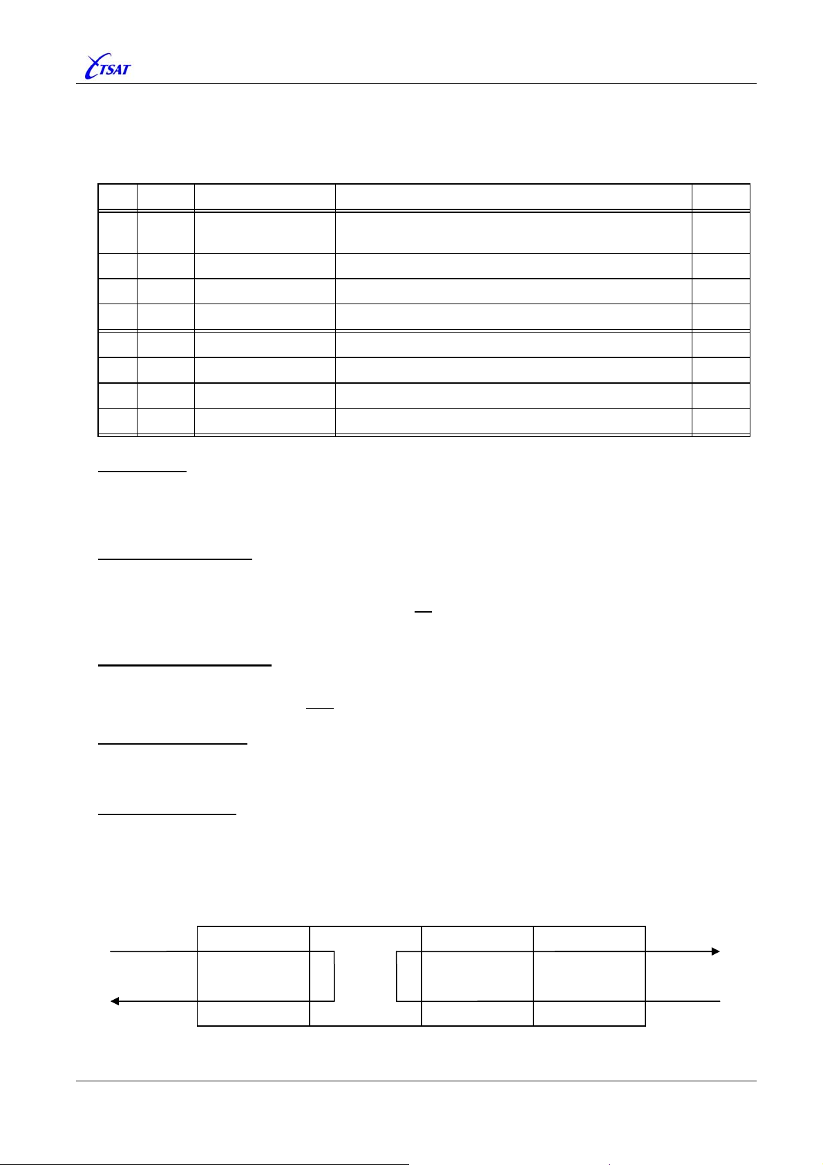
TSAT 3000 - Telemetry and data transfer via SATellite
3.3.6 COM_OPTIONS [n]
Default 0, Range 0…255 (0xFF)
Bit field to control miscellaneous COM options.
Bit Mask Mnemonic Description Ver
0
0x01
KEEP_OPEN
Don’t Close+Open COM when too many errors are
rx’ed.
31.0.0
0x02
1
0x04
2
0x08
3
0x10
4
0x20
5
0x40
6
0x80
7
IGNORE_PFO_ERRORS
DEBUG_PRINT_RX
DEBUG_PRINT_TX
DEBUG_PRINT_ASCII
HIGH_LEVEL_LOOP
Ignore Parity-, Framing- and Overrun-errors. 31.1.1
n/a
n/a
Print all bytes received from COM.
Print all bytes sent to COM.
Print ASCII text – Else HEX data. 31.0.0
Loop all data sent and received to/from COM.
KEEP OPEN
Ver >= 31.0.0: Normally, the COM will be Closed+Opened when more than 10 errors are
received the 10 last seconds (to fix a problem in VxWork-6.2 FTP-Client !!!). Enable this
option will disable this behaviour, and COM will be kept Open forever.
IGNORE PFO ERROR
Ver >= 31.1.1: Normally, characters with Parity-, Framing- or Overrun-errors are discarded. Also
some bytes received immediately before and after the erroneous characters could be
discarded. When this option is enabled, no
useful for some applications). Note:
KERNEL >= 4.0.1 is required.
bytes will be discarded (which could be very
DEBUG PRINT {RX | TX}
Print all data received and/or sent from/to COM to Console.
Ver >= 30.8.0: A message will also be sent to all SERVICE Ports – I.e. the NMS.
DEBUG PRINT ASCII
Ver >= 31.0.0: Normally HEX data will be printed when
DEBUG_PRINT_{RX | TX} is enabled.
Enable this option to print ASCII text.
HIGH LEVEL LOOP
When enabled, data received from the satellite link and sent to COM, will be (software) looped
within the COM module, and handled as it was received from the COM-Driver (i.e. sent back to
PORT and the other (remote) network node).
Data received from the COM-Driver will be looped back to the COM-Driver.
PORT COM COM-Driver Physical Device
Satellite
Link
TSAT 3000 Configuration Parameter Description, January 2013 Page 39 of 124
RS 232
Line
Page 40

TSAT 3000 - Telemetry and data transfer via SATellite
3.4 IP PARAMETERS
3.4.1 IP_ADDRESS_{ETH1 | ETH2 | SAT}
Default <nothing>
Ver <= 30.1.1
Set IP-ADDRESS of Ethernet-A, Ethernet-B and Satellite interfaces.
Note: These MIB parameters are only partly implemented:
• You may read and change FILE value, but this will have no
effect. The Main-Unit will
always boot with values defined in “system.conf”.
• Read CURRENT value will fetch current values from IP-STACK.
• Write CURRENT value will configure IP-STACK with new IP-ADDRESS.
Ver >= 30.2.0
Not Implemented – Parameter is replaced by
IP_ADDRESS_{LANA | LANB | SAT}.
3.4.2 IP_SUBNET_MASK_{ETH1 | ETH2 | SAT}
Default <nothing>
Ver <= 30.1.1
Set SUBNET-MASK of Ethernet-A, Ethernet-B and Satellite interfaces.
Note: These MIB parameters are only partly implemented:
• You may read and change FILE value, but this will have no
effect. The Main-Unit will
always boot with values defined in “system.conf”.
• Read CURRENT value will fetch current values from IP-STACK.
• Write CURRENT value will configure IP-STACK with new IP-ADDRESS.
Ver >= 30.2.0
Not Implemented – Parameter is replaced by
IP_ADDRESS_{LANA | LANB | SAT}.
TSAT 3000 Configuration Parameter Description, January 2013 Page 40 of 124
Page 41

TSAT 3000 - Telemetry and data transfer via SATellite
3.4.3 IP_ADDRESS_{LANA | LANB | SAT}
Default <nothing>
Ver <= 30.1.1
Not Implemented.
Ver >= 30.2.0
Set IP-ADDRESS and SUBNET-MASK of Ethernet-A, Ethernet-B and Satellite interfaces.
You define both IP Address and Network Mask by a single MIB parameter, and it’s also
possible to specify a default
Addresses for HUB and all RTs in a satellite network.
MIBs will also survive a restart of CCU, and if applicable (when MIB is different to <nothing>)
new IP configuration is applied when CCU is starting.
Format: <null>-terminated text string.
<space> within the text string is ignored.
Syntax:
LANA | LANB := <nothing> | <address> [ / <mask> [ / <mask2> ] ]
SAT := <nothing> | <address> [ / <mask> ]
<nothing> :=
<address> := <dot-notation> | <a-number>
<mask>, <mask2> := <dot-notation> | <m-number>
<dot-notation> := <d-number> . <d-number> . <d-number> . <d-number>
<a-number> := <number>
<m-number> := <number> Range 1 … 31, or Bitmap 0x1000.0000 … 0xFFFF.FFFE.
<d-number> := <number> Range 0 … 255.
<number> := <dec-number> | <hex-number>
<dec-number> := *<d-digit>
<hex-number> := [ 0 ] x *<h-digit>
<d-digit> := 0 … 9
<h-digit> := 0 … 9, A … F
Interpretation:
<nothing>: Do nothing – Keep settings from “system.conf”.
<address>: The IP Address is a 32-bit unsigned integer, normally specified with <dot-notation>.
Ex: “192.168.0.100”. It’s also possible to specify a <number>. Ex: “0xC0A80064”,
“3232235620” or combination “192.164.0.x64”.
The special value “0.0.0.0” (or just “0”) will be replaced by default IP Address:
LANA | LANB: “192.168.0.0”.
•
•
SAT: “10.0.0.0”.
The upper bits of IP Address (defined by Network Mask) is the Network Address,
while the lower bits (given by inverse Network Mask) is the Host Address. When the
Host Address is zero, the CCU will generate a default IP Address and Network Mask
which will guarantee unique IP Addresses for HUB and all RTs in a satellite network.
This is explained in more detail further down.
<mask>: The Network Mask is also a 32 bit unsigned integer, with the restriction that all upper
bits should be “1”, while all lower bits should be “0”. Normally, you just specify the
number of upper “1” bits. Ex: “24”. However, it’s also possible to specify <number>
or <dot-notation>. Ex: “0xFFFFFF00” or “255.255.255.0”.
CCU will not
CCU will generate a default Network Mask when <mask> is zero:
• LAN
0xFFFFFF00 (i.e. 24 bits) otherwise.
•
SAT: 0xFFFF0000 (i.e. 16 bits).
IP Address and Network Mask which will generate unique IP
Range 0 … 0xFFFF.FFFE.
Range 0 … 4.294.967.295
Range 0 … 0xFFFF.FFFF
change Network Mask when <mask> is omitted in configuration:
A | LANB: 0xFFFF0000 (i.e. 16 bits) when 16 lower bits of IP Address are “0”.
TSAT 3000 Configuration Parameter Description, January 2013 Page 41 of 124
Page 42
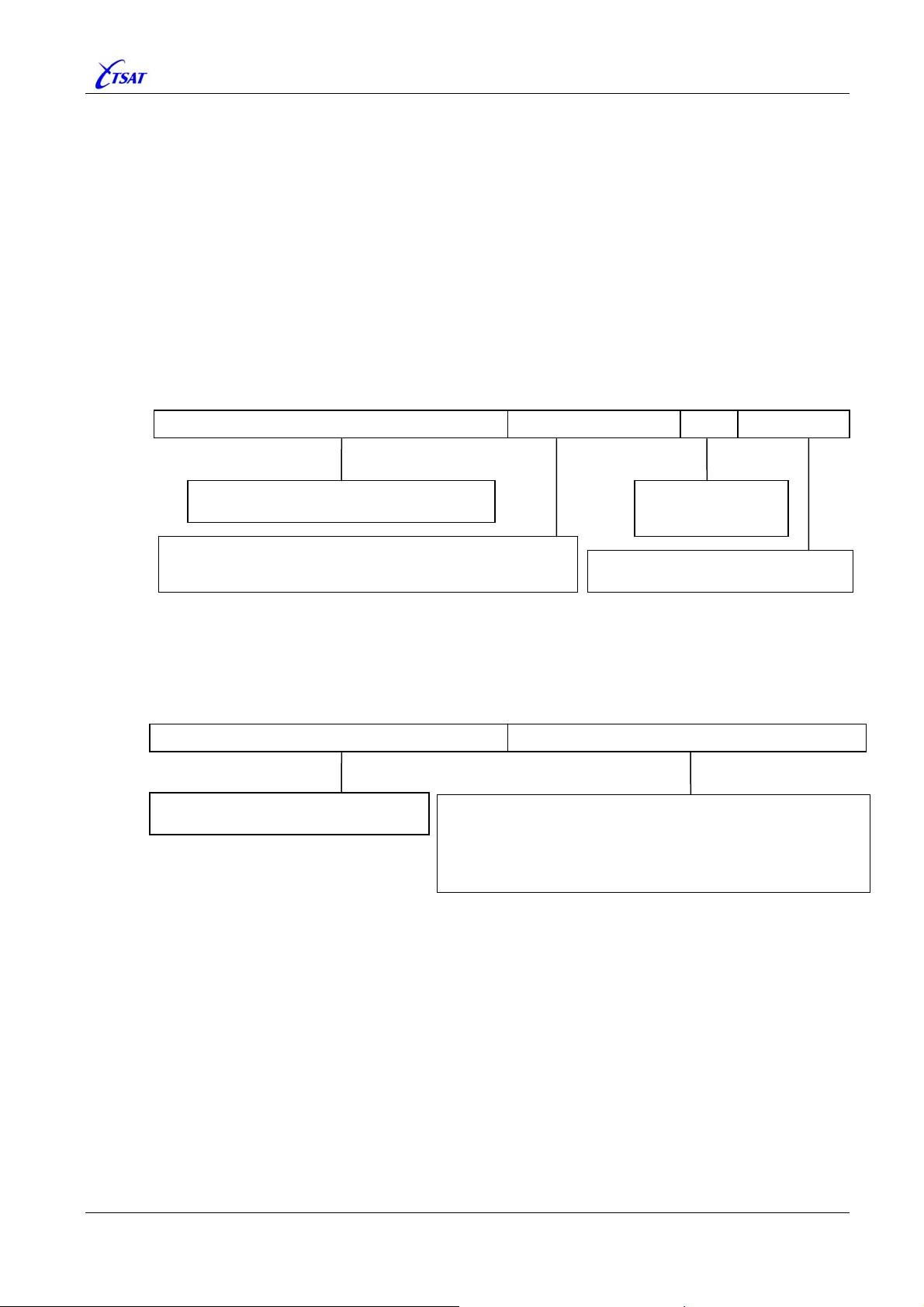
–
-
2
-2–
TSAT 3000 - Telemetry and data transfer via SATellite
<mask2>: Same interpretation as <mask>. This <mask2> is only applicable when CCU is going
to generate default IP Address for the
LANA or LANB interfaces. CCU will use default
Network Mask2 when <mask2> is omitted: 0xFFFFFFF8 (i.e. 29 bits).
Default IP Address:
CCU will generate default IP Address when the Host Address (lower part of given IP Address)
is zero.
• LANA | LANB Interface:
When Network Address is zero: Address = “192.168.0.0”.
When Network Mask is zero: Mask = 0xFFFF0000 (16 bits) when 16 bits Host Address is zero.
Mask = 0xFFFFFF00 (24 bits) when 16 bits Host Address isn’t zero.
When Network Mask-2 is undefined: Mask-2 = 0xFFFFFFF8 (29 bits).
Default 32 bits IP Address is generated by concatenating Network Address, Node Address, LanA/B and Host
Address as shown in figure below:
Network Address Node Address LanA/B Host Address
Network Address = Default or specified
Number of bits = Network Mask
HUB Node Address = 0
RT Node Address =
Number of bits = Network Mask
• SAT Interface:
When Network Address is zero: Address = “10.0.0.0”.
When Network Mask is zero: Mask = 0xFFFF0000 (16 bits).
Default 32 bits IP Address is generated by concatenating Network Address and Host/Node Address as shown in
figure below:
Network Address = Default or specified
Number of bits = Network Mask
LANA = 0
LANB = 1
=
NET_RT_ADDRESS
Network Mask –1
Host Address = 1
Number of bits = 32
Network Mask
Network Address Host & Node Address
HUB Node Address = 0xFFFFFF01 & Inverse Network Mask
RT Node Address =
Number of bits = 32 – Network Mask
Note: HUB Node Address will be shifted right some bits when
Network Mask is greater than 24 bits.
NET_RT_ADDRESS
TSAT 3000 Configuration Parameter Description, January 2013 Page 42 of 124
Page 43
TSAT 3000 - Telemetry and data transfer via SATellite
Some examples may clarify how CCU will generate default IP Addresses:
Default Network Address, Network Mask and Network Mask-2
MIB LANA LANB SAT Applied at Node
0.0.0.0 / 0
Default Network Mask and Network Mask-2 – Specify Network Address:
MIB LANA LANB SAT Applied at Node
192.100.0.0 / 0
Default Network Address and Network Mask-2 – Specify Network Mask:
MIB LANA LANB SAT Applied at Node
0.0.0.0 / 22
Default Network Address and Network Mask – Specify Network Mask-2:
MIB LANA LANB SAT Applied at Node
0.0.0.0 / / 28
192.168.0.1 / 29 192.168.0.9 / 29 10.0.255.1 / 16 HUB
192.168.0.49 / 29 192.168.0.57 / 29 10.0.0.3 / 16 RT 3
192.100.0.1 / 29 192.100.0.9 / 29 192.100.255.1 / 16 HUB
192.100.0.49 / 29 192.100.0.57 / 29 192.100.0.3 / 16 RT 3
192.168.0.1 / 29 192.168.0.9 / 29 10.0.3.1 / 22 HUB
192.168.0.49 / 29 192.168.0.57 / 29 10.0.0.3 / 22 RT 3
192.168.0.1 / 28 192.168.0.17 / 28 n/a HUB
192.168.0.97 / 28 192.168.0.113 / 28 n/a RT 3
ERROR in Ver <= 31.0.1
A mismatch introduced with
KERNEL 3.0.1 (Release 3.0.1) caused an erroneous Network-
Mask when the IP address was changed.
Example: Setting
This apply to CCU version <= 31.0.1 together with
IP_ADDRESS_SAT = “10.0.3.1 / 22” would give IP address = “10.0.3.1 / 8”.
KERNEL >= 3.0.1.
Error is corrected in CCU version 31.1.0.
TSAT 3000 Configuration Parameter Description, January 2013 Page 43 of 124
Page 44

TSAT 3000 - Telemetry and data transfer via SATellite
3.4.4 IP_ROUTE [n]
Default <nothing>
Ver <= 30.1.1
Not Used.
Ver >= 30.2.0
The MIB parameters
The maximum numbers of
below:
When MIB is different to <empty>, the new Route will be added when CCU is starting, and you
may also change or delete the Route while CCU is running. The Routes defined by
[1…100]
will not affect the Routes defined in “system.conf”, but be additional Routes.
Format: <null>-terminated text string.
<space> within the text string is ignored.
Syntax:
IP_ROUTE := <empty> | <destination> [ / <mask> ] <gateway> [ <flags> ]
<empty> :=
<destination> := <address>
<gateway> := <address>
<address> := <dot-notation> | <a-number>
<mask>, := <dot-notation> | <m-number>
<flags> := <f-number>
<dot-notation> := <d-number> . <d-number> . <d-number> . <d-number>
<a-number> := <number>
<f-number> := <number> Range 0 … 0xFFFF.FFFF.
<m-number> := <number> Range 1 … 31, or Bitmap 0x1000.0000 … 0xFFFF.FFFE.
<d-number> := <number>
<number> := <dec-number> | <hex-number>
<dec-number> := *<d-digit>
<hex-number> := [ 0 ] x *<h-digit>
<d-digit> := 0 … 9
<h-digit> := 0 … 9, A … F
Interpretation:
<empty>: Do nothing.
<destination>: The Destination is a 32-bit unsigned integer, normally specified with <dot-
IP_ROUTE [1…64] were defined in older CCU versions, but had no effect.
IP_ROUTE is increased to 100, and are now used as described
IP_ROUTE
Range 0 … 0xFFFF.FFFE.
Range 0 … 255.
Range 0 … 4.294.967.295
Range 0 … 0xFFFF.FFFF
notation>. Ex: “192.168.0.0”. It’s also possible to specify a <number>. Ex:
“0xC0A80000”, “3232235520” or combination “192.xA8.0.0”.
The upper bits of Destination (defined by Network Mask) are the Destination
Network Address. Only these bits are used – the lower bits are ignored.
The special value “0.0.0.0” (or just “0”) will be replaced by default
Destination:
• “0.0.0.0” when Gateway is specified – i.e. not
replaced.
• “192.168.0.0” when Gateway is zero – i.e. Default Routes.
TSAT 3000 Configuration Parameter Description, January 2013 Page 44 of 124
Page 45

TSAT 3000 - Telemetry and data transfer via SATellite
<mask>: The Network Mask is also a 32 bit unsigned integer, with the restriction that
all upper bits should be “1”, while all lower bits should be “0”. Normally, you
just specify the number of upper “1” bits. Ex: “24”. However, it’s also possible
to specify <number> or <dot-notation>. Ex: “0xFFFFFF00” or
“255.255.255.0”. CCU will generate a default Network Mask when <mask> is
omitted in configuration:
• 0xFFFFFF00 (i.e. 24 bits) when Gateway is specified.
• 0xFFFFFFF0 (i.e. 28 bits) when Gateway is zero – i.e. Default Routes .
<gateway>: The Gateway is an IP Address with the same syntax as Destination. All
packets to IP Addresses matching the Destination Network Address will be
routed to the specified Gateway. The special value “0.0.0.0” (or just “0”) will
make CCU to generate a set of default Routes, as specified further down.
<flags>: The Flags is also a 32 bit unsigned integer, specified as a <number>. The
following options are used by the IP-STACK:
RTF_UP 0x0001 // route usable
RTF_GATEWAY 0x0002 // destination is a gateway
RTF_HOST 0x0004 // host entry (net otherwise)
RTF_REJECT 0x0008 // host or net unreachable
RTF_DYNAMIC 0x0010 // created dynamically (by redirect)
RTF_MODIFIED 0x0020 // modified dynamically (by redirect)
RTF_DONE 0x0040 // message confirmed
RTF_MASK 0x0080 // subnet mask present
RTF_CLONING 0x0100 // generate new routes on use
RTF_XRESOLVE 0x0200 // external daemon resolves name
RTF_LLINFO 0x0400 // generated by ARP or ESIS
RTF_STATIC 0x0800 // manually added
RTF_BLACKHOLE 0x1000 // just discard packets (during updates)
RTF_PROTO2 0x4000 // protocol specific routing flag
RTF_PROTO1 0x8000 // protocol specific routing flag
RTF_MGMT 0x2000 // modified by management proto
RTF_REP_NODE 0x4000 // Representative Node in the Pat tree
RTF_CLONED 0x4000 // Child route holding path MTU results
RTF_DELETE 0x8000 // Unused route scheduled for deletion
The CCU will always apply the RTF_STATIC (0x0800) option when Route is
added.
Default Route
CCU will generate a set of default Routes when Gateway is zero (“0.0.0.0” or just “0”).
THIS FUNCTION IS CURRENTLY NOT IMPLEMENTED.
TSAT 3000 Configuration Parameter Description, January 2013 Page 45 of 124
Page 46
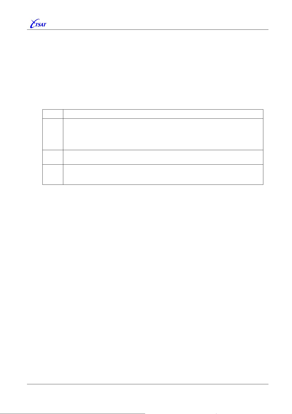
TSAT 3000 - Telemetry and data transfer via SATellite
3.4.5 IP_LINGER_FTP
Default 60, Range –1…120
Ver <= 30.6.1
Not Implemented.
Ver >= 30.7.0 + KERNEL >= 3.2.1
This MIB is defining a timeout parameter of the local FTP server. It will set the maximum time
from the FTP server has sent the last data-packet, until the ftp-data-socket will be closed. The
last part of retrieved files (especially smaller files) may be lost if this timeout is set too low.
Default value is 60 (i.e. 1 minute). Legal values are:
Value Description
On close(), the underlying stack attempts to gracefully shutdown the connection after
ensuring all unsent data is sent. The stack also ensures that sent data is acknowledged
-1
by the peer. The stack will perform the above-mentioned graceful shutdown in the
background (after the call to close() returns), regardless of whether the socket is blocking
or non-blocking.
A close() returns immediately. The underlying stack discards any unsent data, and sends
0
a RST (reset) to the peer (this is termed a hard or abortive close).
A close() will either block (if a blocking socket) or fail (if non-blocking) until a graceful
1 - 120
shutdown completes or the time specified time elapses (time-out). Upon time-out the
stack sends a RST (reset) to the peer.
TSAT 3000 Configuration Parameter Description, January 2013 Page 46 of 124
Page 47
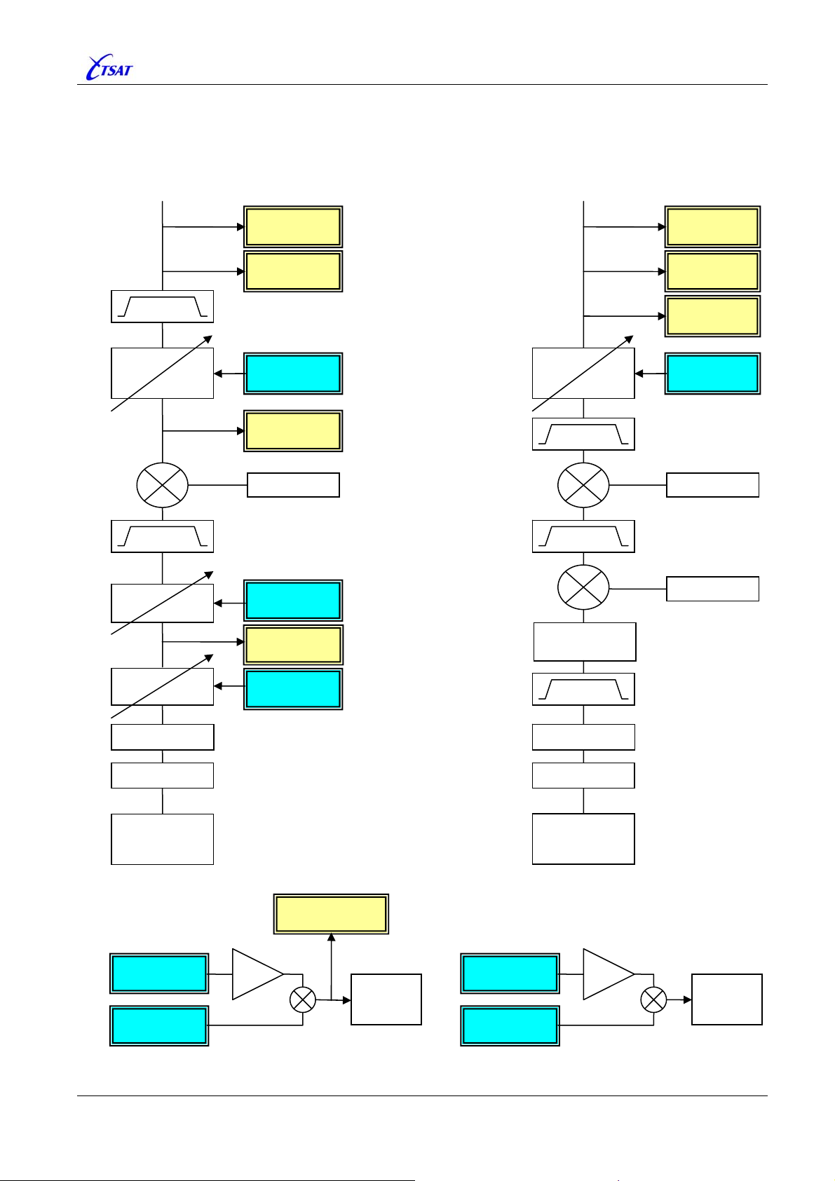
TSAT 3000 - Telemetry and data transfer via SATellite
3.5 ADC + DAC PARAMETERS
Main-Unit is equipped with 8 D/A-Converters (CYAN) and 8 A/D-Converters (YELLOW).
RX
950 - 1450
Variable
ATTENUATOR
0 ... 40 dB
BW 5 MHz
Variable
RX GAIN 1
TX
ADC
LNB Voltage
ADC
LNB Current
DAC
Rx-Attenuator
ADC
Rx-RF Level
? MHz ? MHz
DAC
Rx-Gain 1
Variable
TX GAIN
950 - 1450
BW 20 MHz
BUC Voltage
BUC Current
Tx-RF Level
Tx-Gain
? MHz
ADC
ADC
ADC
DAC
TX Gain
BW 3 Mhz
D/A
GRAY-Ship
DSP
x 16
OCXO
Variable
RX GAIN 2
A/D
GRAY-Ship
DSP
DAC
TCXO High
DAC
TCXO Low
x 16
ADC
Rx-IF Level
DAC
Rx-Gain 2
TCXO Voltage
ADC
TCXO
DAC
OCXO High
DAC
OCXO Low
TSAT 3000 Configuration Parameter Description, January 2013 Page 47 of 124
Page 48

TSAT 3000 - Telemetry and data transfer via SATellite
3.5.1 ADC_SAMPLE_COUNT
Default 1, Range 1…100
Used when the operator fetch a measurement from one of onboard A/D-Converters: ADC_{1 | 2 |
3 | 4 | 5 | 6 | 7 | 8}_XXX
. The A/D-Converter will be read the specified number of times, and the
average value returned.
3.5.2 ADC_{1 | 2 | 3 | 4 | 5 | 6 | 7 | 8}_XXX
Read-Only
You can read the CURRENT value of all onboard A/D-Converters (12-bits). Each time you fetch a
value, the A/D-Converter will be read
value returned.
ADC_SAMPLE_COUNT number of times, and the average
The MIB names describe the usage of the A/D-Converter:
• ADC_1_TX_RF_LEVEL
• ADC_2_RX_RF_LEVEL
• ADC_3_TCXO_VOLTAGE Ver <= 30.1.1: MIB is called
• ADC_4_RX_IF_LEVEL Ver <= 31.0.1: MIB is called
ADC_3_TXCO_VOLTAGE.
ADC_4_TX_GAIN.
• ADC_5_BUC_VOLTAGE
• ADC_6_LNB_VOLTAGE
• ADC_7_LNB_CURRENT
• ADC_8_BUC_CURRENT
See also
GAIN PARAMETERS.
3.5.3 DAC_{11 | 12 | 13 | 14 | 21 | 22 | 23 | 24}_XXX
Default 0, Range 0…4095 (0x0FFF) – Volatile
You can both read and write the CURRENT value of all onboard D/A-Converters (12-bits).
The MIB names describe the usage of the D/A-Converter:
• DAC_11_TCXO_REF_HIGH
• DAC_12_TCXO_REF_LOW
• DAC_13_OCXO_REF_HIGH
• DAC_14_OCXO_REF_LOW
• DAC_21_TX_GAIN
• DAC_22_RX_VGA1
• DAC_23_RX_VGA2
• DAC_24_RX_ATT
See also
GAIN PARAMETERS.
TSAT 3000 Configuration Parameter Description, January 2013 Page 48 of 124
Page 49
TSAT 3000 - Telemetry and data transfer via SATellite
3.5.4 DAC_{TCXO | OCXO}_REF
Default 0, Range 0…17391
Change these MIBs to modify the default TCXO and/or OCXO Oscillator settings defined in
“hw.conf”, or just read-back CURRENT value.
Ver <= 30.1.1
Not Implemented
Ver >= 30.2.0:
Value Description
0 Do nothing – Keep settings from “hw.conf”.
1 … 17391 Initialize Oscillator ref voltage to a value between MIN and MAX.
Note 1: HUB Main-Unit is equipped with OCXO, while RT Main-Unit has a TCXO. You can
always read and change both MIBs (i.e. DAC setting), but change will only have effect
when Main-Unit is equipped with selected Oscillator.
Note 2: Normally, fabric calibration values defined in “hw.conf” should always be used. These
MIBs are mostly intended for test purposes.
Note 3: Two 10 bits DACs (using bits 2…10 – 0x0FFC) are used to generate TCXO / OCXO
ref voltage.
• Read MIB value is found by: ( (
• Write MIB value:
• Maximum value is 0x3FF x 16 + 0x3FF = 1023 x 17 = 17391.
• See also
Note 4: RTs Ver >= 30.2.0 may also adjust the TCXO ref voltage so that its own TCXO
Oscillator is running at exact
This function apply also to RT Main-Unit (with TCXO) operating as HUB in LISTEN Mode –
I.e. bit 15 (0x8000 –
This TCXO adjust function is enabled by bit 16 (0x0001.0000 – UTILITY_ADJUST_TCXO) in
UTL_UTILITY_MASK.
HIGH-DAC is multiplied by 16 to generate ref voltage. Therefore:
HIGH-DAC >> 2) x 16 ) + (LOW-DAC >> 2).
LOW- and HIGH-DAC values are found by reverse calculation.
Ver >= 31.0.1: The function to find
DAC values is slightly changed – to make the
LOW- and HIGH-DAC values as equal to each other as possible.
DAC_{11 | 12 | 13 | 14 | 21 | 22 | 23 | 24}_XXX.
same frequency as the HUB’s OCXO Oscillator.
UTILITY_CCU_LISTEN_TO_CCU) in UTL_UTILITY_MASK is enabled.
TSAT 3000 Configuration Parameter Description, January 2013 Page 49 of 124
Page 50

TSAT 3000 - Telemetry and data transfer via SATellite
3.6 SWITCH PARAMETERS
Main-Unit is equipped with a number of switches to control miscellaneous functions.
3.6.1 SWITCH_{RX | TX}_XXX
Default 0, Range 0…1 – Volatile
Ver <= 30.3.1
Not Implemented.
Ver >= 30.4.0
You can both read and write the CURRENT value of all onboard switches.
The MIB names describe the usage of these switches:
• SWITCH_RX_SIGNAL Enable/disable RX Signal.
• SWITCH_RX_10MHZ Enable/disable 10 MHz reference to LNB.
• SWITCH_RX_LNB_POWER Enable/disable LNB power.
• SWITCH_RX_POWER Enable/disable RX power.
• SWITCH_TX_SIGNAL Enable/disable TX signal.
• SWITCH_TX_10MHZ Enable/disable 10 MHz reference to BUC.
• SWITCH_TX_BUC_POWER Enable/disable BUC power.
• SWITCH_TX_POWER Enable/disable TX power.
• SWITCH_TX_RESET Enable/disable TX Reset.
3.6.2 SWITCH_RX_{10MHZ | LNB_POWER}_DELAY
Default 0, Range 0…60
Ver <= 31.0.0
Not Implemented.
Ver >= 31.0.1
By setting
SWITCH_RX_10MHZ_DELAY and/or SWITCH_RX_LNB_POWER_DELAY different to
zero, the DC Power and/or 10 MHz reference to LNB will be turned OFF when CCU is booting,
and turned ON after the specified time [seconds].
This function could perhaps make some LNBs with strange behavior (or impedance
mismatch?) to operate normally. It’s recommended to set
than
SWITCH_RX_LNB_POWER_DELAY, so that the 10 MHz will be turned ON before the
SWITCH_RX_10MHZ_DELAY less
Power is turned ON. This functionality is disabled when:
• MIB value is zero.
• Configuration parameters
UseLNBPower / UseLNBRefSignal in “hw.conf” are disabled.
• Startup-tests have detected RX fault and disabled LNB Power or LNB Reference.
•
SWITCH_RX_LNB_POWER or SWITCH_RX_10MHZ have been temporary disabled by operator.
Note 1: This function will normally not
be activated when DSP is restarted, but you may send
the Text-Command “dsp init lnb” to manually toggle LNB Power and/or 10 MHz
OFF-ON (as specified by MIB values).
Note 2: Ver >= 30.5.0 – LNB Power will always
Spectrum has been read 20 times, without being able to find HUB carrier.
be turned OFF for at least 2 seconds when
TSAT 3000 Configuration Parameter Description, January 2013 Page 50 of 124
Page 51
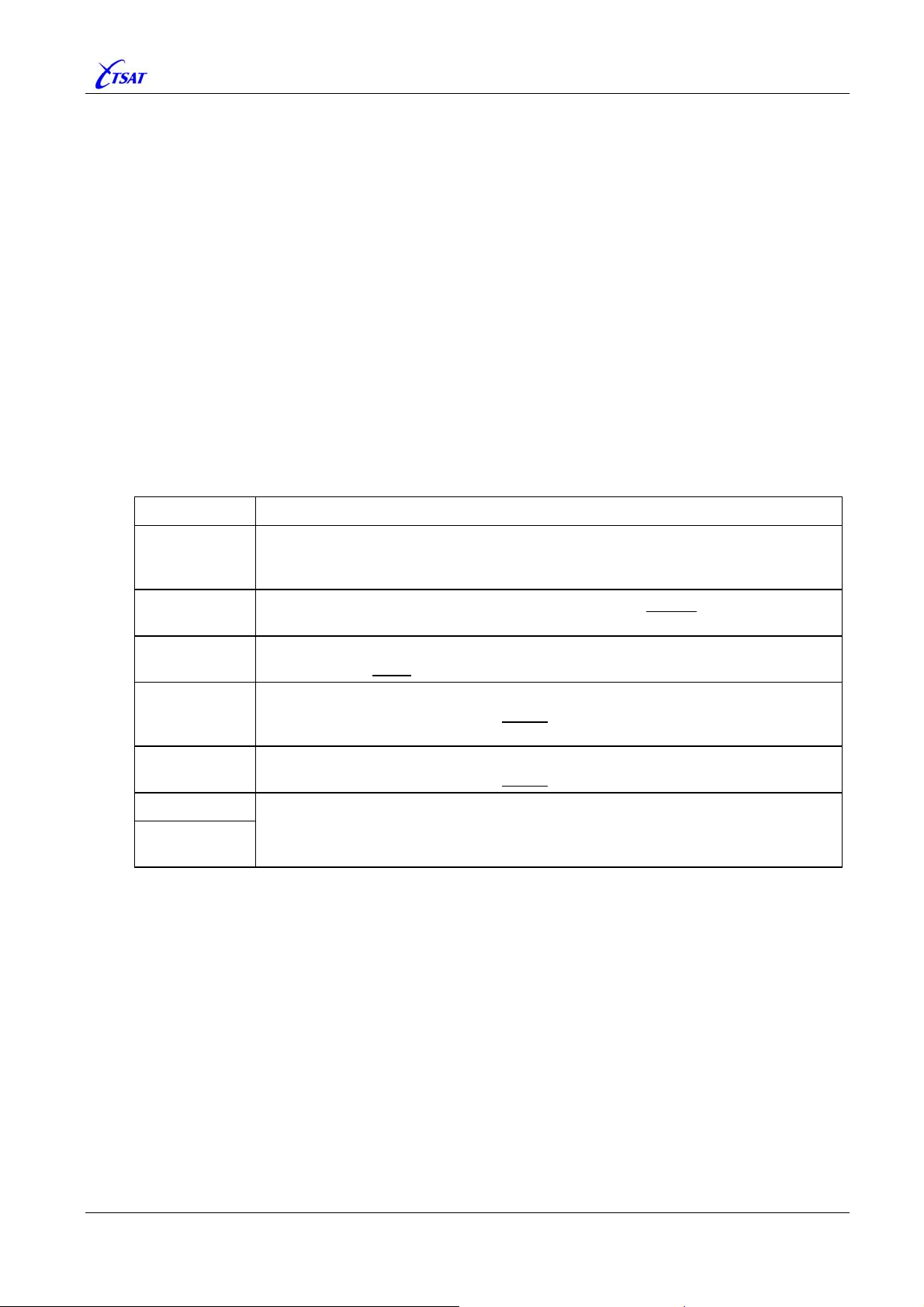
TSAT 3000 - Telemetry and data transfer via SATellite
3.7 GAIN PARAMETERS
Rx/Tx Gain is controlled by reading onboard A/D-Converters, and writing to the onboard D/AConverters. See description of MIB parameters below, and
ADC + DAC PARAMETERS.
3.7.1 GAIN_TX_REF
Ver <= 30.4.1: Default 0.0, Range –50.0… 0.0
Ver >= 30.5.0: Default 0.0, Range –50.0…4095.0
Control the “Automatic Tx-Gain Control (AGC)” facility.
Ver <= 30.5.0:
Not Used.
Ver >= 30.6.0:
Enable or disable Tx AGC.
Tx-Detector value (
DAC (
DAC setting is limited to a value in the range defined by
DAC_21_TX_GAIN) regulated up/down until desired output level is reached. The Tx-Gain
Value Description
ADC_1_TX_RF_LEVEL) is fetched when packets are sent, and Tx-Gain
GAIN_TX_DAC_{MIN | MAX}.
Enable AGC. Output level given in dBm.
–50.0 … –0.0
0.0
1.0
2.0
3.0
4.0 … 4095.0
ELSE
i.e. 0.0 … 4.0
Convert dBm => Target Tx-Detector value, and adjust Tx-Gain DAC until desired
Tx-Detector is reached.
Disable AGC. Tx-Detector is nevertheless fetched each second
measurements to the NMS ‘TSAT 3000 Hardware Diagnostics’ window.
TEST. Disable AGC.
Tx-Detector will never
TEST. Disable AGC.
Tx-Detector is fetched each time a packet is sent on both Primary and Secondary
Inbound carrier – See Note 3 next page
TEST. Disable AGC.
Tx-Detector is fetched each time a packet
TEST. Enable AGC. Output level given in Detector units.
Adjust Tx-Gain DAC until desired Tx-Detector value (4…4095) is reached.
be fetched.
is sent, and average value calculated.
to give
You may enable or disable:
• “Automatic Tx-Gain Control” - GAIN_TX_REF.
• “Static Tx-Gain” -
• “End-to-End Tx-Gain Control” -
GAIN_TX_OVERRIDE.
GAIN_TX_END2END_TARGET.
The priority of these 3 Tx-Gain control mechanisms is:
1) Set “Static Tx-Gain” when this function is enabled.
2) With Tx-Signal (
SWITCH_TX_SIGNAL) disabled: Adjust to desired output level when
“Automatic Tx-Gain Control” is enabled. Then enable the Tx-Signal.
3) After initial adjustment, the “End-to-End Tx-Gain” will regulate output level – if it is enabled.
Otherwise, “Automatic Tx-Gain” will take control (when it’s enabled).
Note 1: For your information:
1 dBm = approx. 66 Tx-Detector units
1 dBm = approx. 53 Tx-Gain DAC units.
1 dBm = approx. 1 dB E
received at remote side.
b/N0
TSAT 3000 Configuration Parameter Description, January 2013 Page 51 of 124
Page 52

TSAT 3000 - Telemetry and data transfer via SATellite
Note 2: When AGC is enabled, the Tx-Detector will normally be fetched each second
, except
when any adjustments to the Tx-Gain DAC shall be done. In this case, the Tx-Detector is
fetched each time a packet
is sent – to speed up regulation time.
Note 3: An RT in “Multi Inbound Link” (MIL) network (See
PHL_TX_RT_FREQUENCY_2) may
send on both Primary and Secondary Inbound carriers. Due to ripple in Tx-SAW-filter, the
output level on Secondary Inbound carrier may be +/– 1 dBm, compared to the Primary
Inbound carrier. Therefore, the Tx-Detector will normally only
be fetched when packets are
sent on Primary Inbound carrier – and the configured output level is applied to the Primary
Inbound carrier.
Note 4: A Slave-HUB in “Multi Inbound Link” (MIL) network (see
cannot transmit. CCU Ver >= 30.8.0 will then always set
PHL_TX_RT_FREQUENCY_2)
GAIN_TX_REF = 1.0 (disable
AGC) when it’s booting.
ERROR 1:
GAIN_TX_REF should always be 1.0 (disable AGC) when CCU Ver >= 30.6.0 is
used together with COREAPP Ver <= 2.1.1 (i.e. Release <= 3.1.0). Otherwise, software
incompatibility could cause BUC and/or LNB to be turned OFF, and unit will reboot after
some time.
ERROR 2:
GAIN_TX_REF should preferable be 1.0 (disable AGC) when CCU Ver 31.0.0 or
31.0.1 is used together with DSP Ver <= 2.3.1 (i.e. Release <= 3.5.0). Otherwise, an
“Invalid Detector Sample” message will be issued each second.
3.7.2 GAIN_TX_OVERRIDE
Default 0, Range 0…4095
Set Tx-Gain DAC value.
Value Description
0 Don’t set Tx-Gain DAC. Keep value defined in “hw.conf”.
Set Tx-Gain DAC to initial value. The setting will be refreshed:
1 … 4095
• On HUB: When HUB is starting to search for own carrier.
On RT: When HUB carrier is found.
•
Note: A Slave-HUB in “Multi Inbound Link” (MIL) network (see
cannot transmit. CCU Ver >= 30.8.0 will then always set
GAIN_TX_OVERRIDE = 1 (very low
output) when it’s booting.
PHL_TX_RT_FREQUENCY_2)
TSAT 3000 Configuration Parameter Description, January 2013 Page 52 of 124
Page 53

TSAT 3000 - Telemetry and data transfer via SATellite
3.7.3 GAIN_TX_END2END_TARGET
Default 0.0, Range 0.0 + 6.0…20.0
Control the “End-to-End Tx-Gain” facility.
Value Description
0.0 Disable “End-to-End Tx-Gain” facility.
6.0 … 20.0 Enable “End-to-End Tx-Gain” facility.
When enabled, the Tx-Gain DAC is adjusted in small steps until the measured Receive-Level
(E
) at the remote side is equal GAIN_TX_END2END_TARGET [dB]. However, the Tx-Gain DAC
b/N0
setting is limited to a value in the range defined by
• Incremented – When the signal level received at the other side of the
link is <
GAIN_TX_END2END_TARGET – DELTA [dB].
• Decremented – When the signal level received at the other side of the
link is >
GAIN_TX_END2END_TARGET + DELTA [dB].
Ver <= 30.2.0: DELTA = 0.5 dB.
Ver == 30.3.0:
Ver >= 30.3.1:
DELTA = 0.3 dB.
DELTA = 0.2 dB.
Ver >= 31.1.0: Gain regulation is temporary stopped when Tx-Gain DAC has been changed more
than 500 units, and the measured (average) receive signal on remote side has changed less
than expected (500 units = approx 3.3 dB).
The CCU is detecting the signal level, received at the other side of the link:
• The signal levels at which the HUB is receiving RTs are signalled back to RTs in
packets.
• The signal level at which the RT is receiving HUB is signalled back to HUB in
packets. The HUB will then adjust its Tx-Gain DAC so that the average
equal
GAIN_TX_END2END_TARGET [dB].
The function to detect received signal level is different on the various CCU versions:
HUB + RT Ver <= 30.2.0: Sliding average of last 16
RT Ver >= 30.3.0: Sliding average of last 32
HUB Ver == 30.3.0: Sliding average of last 32 received OK packets.
Collided packets (detected by PPR) are discarded from measurements.
OK packets with E
< 0.9 x average Eb/N0 are also discarded (because this could
b/N0
be collided packets), except packets received in slot-zero (normally
HUB Ver == 30.3.1: Sliding average of last 32 received OK packets, except when the
received E
is more than 1.5 dB different to average Eb/N0. In the latter case, this
b/N0
measurement will be used immediately (to avoid problems with End-to-End Gain
Control).
Collided packets (detected by PPR) are discarded from measurements.
OK packets with E
< 0.9 x average Eb/N0 are also discarded (because this could
b/N0
be collided packets), except packets received in slot-zero (normally
HUB Ver >= 30.4.0: Same behaviour as version 30.3.1, except when the received E
more than 1.5 dB different to average E
latter case, this measurement will be used immediately (to avoid problems with Endto-End Gain Control).
Note: A Slave-HUB in “Multi Inbound Link” (MIL) network (see PHL_TX_RT_FREQUENCY_2)
cannot transmit. CCU Ver >= 30.8.0 will then always set
(disable this facility) when it’s booting.
See also GAIN_TX_REF.
GAIN_TX_DAC_{MIN | MAX}.
receive level at RTs is
received OK packets.
received OK packets.
POLL_ACK).
POLL_ACK).
in two following slot-zero packets. In the
b/N0
GAIN_TX_END2END_TARGET = 0
SYNC
POLL_ACK
is
b/N0
TSAT 3000 Configuration Parameter Description, January 2013 Page 53 of 124
Page 54
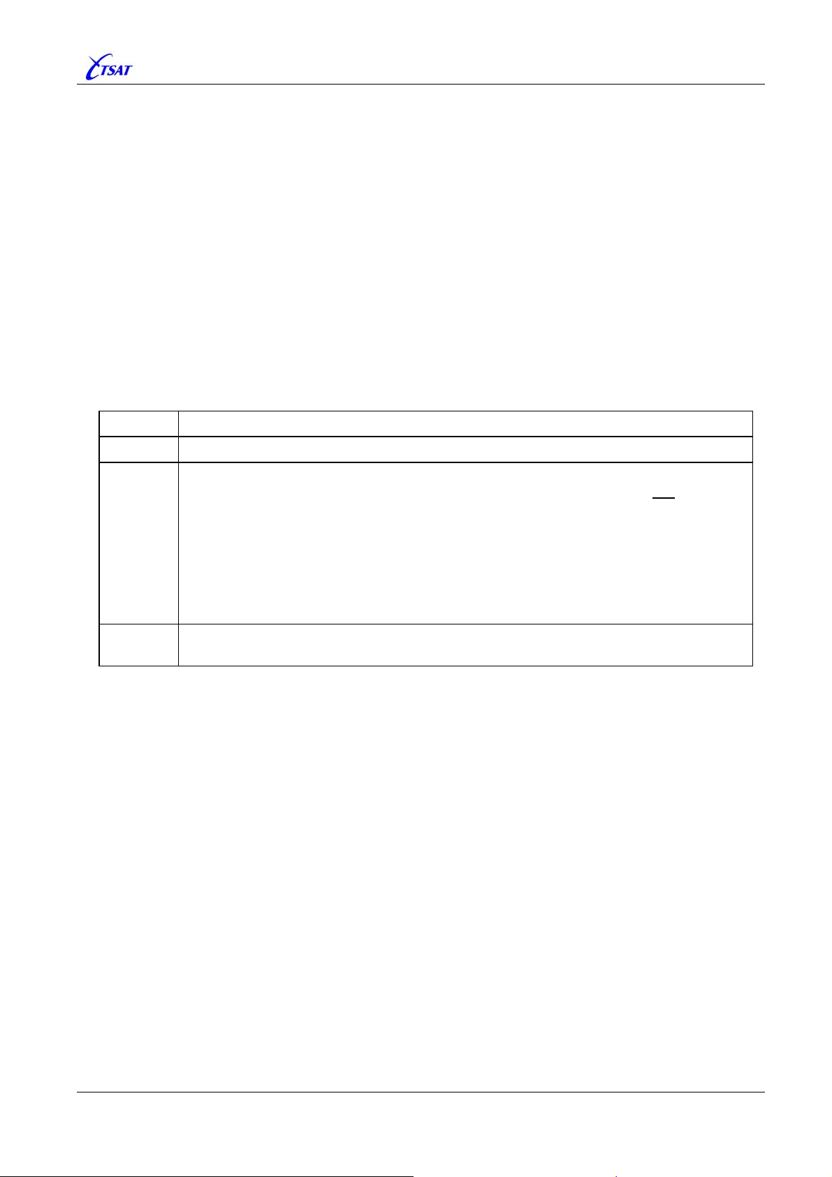
TSAT 3000 - Telemetry and data transfer via SATellite
3.7.4 GAIN_TX_DAC_{MIN | MAX}
MIN: Default 1000, Range 0…4095
MAX: Default 3000, Range 0…4095
Control the “Automatic Tx-Gain” and “End-to-End Tx-Gain” facilities.
Defines the minimum and maximum value of Tx-Gain DAC when one of these facilities are
enabled (
GAIN_TX_REF < 0.0 dBm (Ver >= 30.6.0) OR GAIN_TX_END2END_TARGET >= 6.0 dB).
Note: These MIBs are named
GAIN_TX_END2END_DAC_{MIN | MAX} in CCU Ver <= 30.4.1.
3.7.5 GAIN_RX_ATTENUATOR
Default –1.0, Range –2.0 + –1.0 + 0.0…40.0
Set Rx-Attenuator DAC value.
Value Description
–2.0 Don’t set Rx-Attenuator DAC. Keep value defined in “hw.conf”.
–1.0
0.0 … 40.0
Adjust Rx-Attenuator DAC, so that received Rx-RF-Level is measured to be 1.1 +/– 0.05 V.
The adjustment is done when CURRENT value is changed to –1.0, and the first
time:
• On HUB: When HUB is starting to search for own carrier.
• On RT: When HUB carrier is found.
The CCU will try to adjust Rx-Attenuator DAC maximum 10 times with 1 second intervals.
WARNING will be given if desired Rx-RF-Level (1.05 … 1.15 V) cannot be achieved.
A
The operator may read back the CURRENT Rx-Attenuator DAC setting – converted to
[dB]:
GAIN_RX_ATTENUATOR = INT( ( (4095 – DAC) x 40) / 40.95) / 100.0.
Set Rx-Attenuator DAC to a value so that desired attenuation [dB] is achieved.
Actual DAC value is given by: 4095 – INT(
GAIN_RX_ATTENUATOR x 4095.0 / 40.0 + 0.5)
TSAT 3000 Configuration Parameter Description, January 2013 Page 54 of 124
Page 55
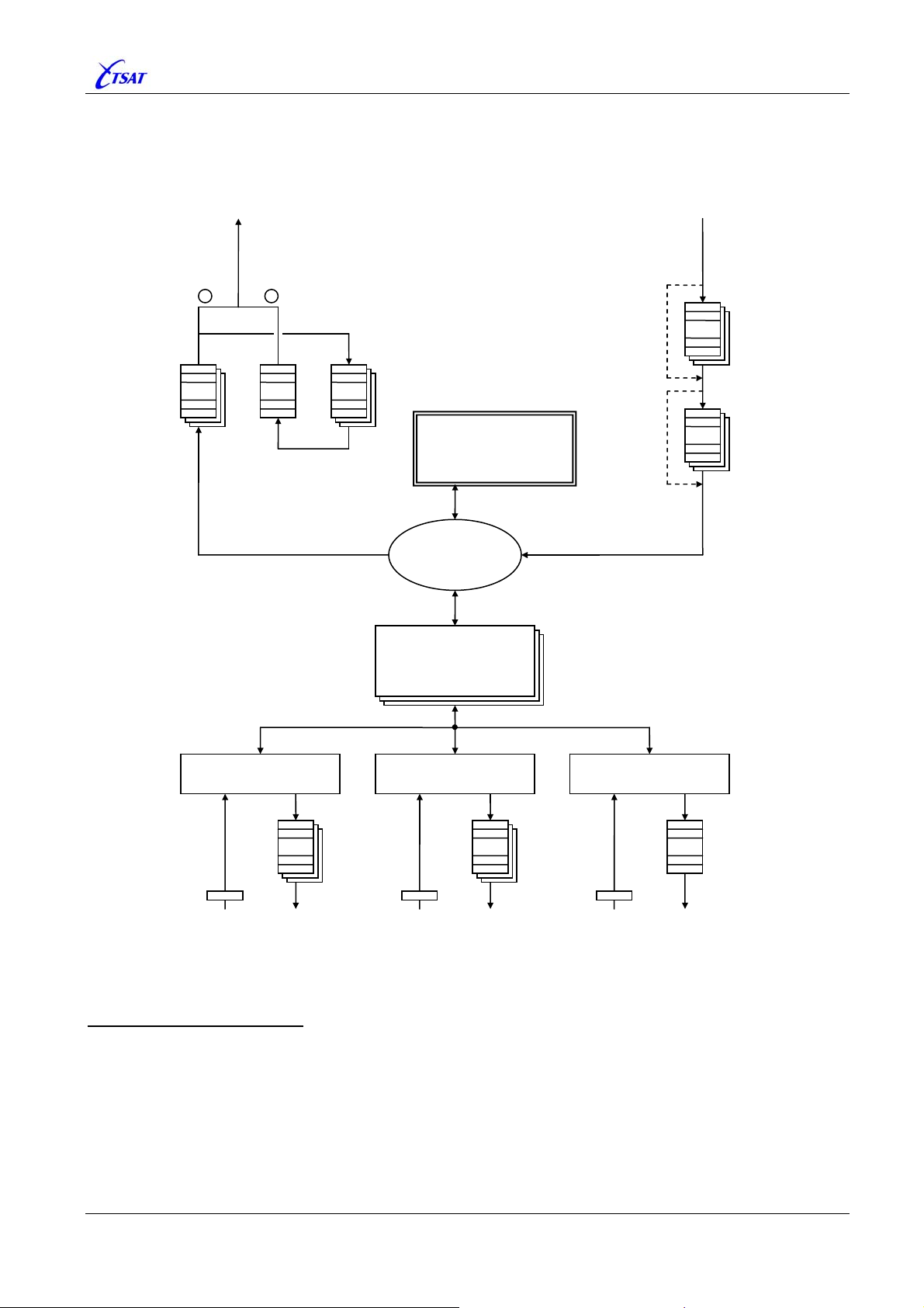
A
TSAT 3000 - Telemetry and data transfer via SATellite
3.8 LINK LAYER PARAMETERS
Overview of CCU Transmission- and Send-Queues:
Priority
Transmission
Queue
TX to Satellite
2
: : :
1
Retransmission
Queue
cknowledge
Queue
MANAGEMENT
ROUTE
PORTs
RX from Satellite
Secure-Link
RX Queue
:
Packetizer
:
RX Queue
COM SOCKET NETWORK
Send
Queue
:
RX TX
RX TX
Send
Queue
:
Receive Receive Receive
RX TX
Send
Queue
:
Priority Transmission Queue
All packets to Satellite Link are stored in this queue prior to transmission.
• One queue for each Priority-0 … 7.
• High-priority-queues are emptied before low-priority-queues.
• Max total size of all queues is defined by
LCC_TX_QUE_SIZE packets.
• Connected applications will be flow-controlled, based on number of packets stored in this queue.
TSAT 3000 Configuration Parameter Description, January 2013 Page 55 of 124
Page 56

TSAT 3000 - Telemetry and data transfer via SATellite
Acknowledge Queue
Sent Secure-Link packets are temporary stored in this queue, and removed when acknowledge from
remote unit is received. Timeout (or request for retransmission) will make a copy of packet and put
in Retransmission-Queue.
• HUB: One queue for each Link. RT: One queue.
• Max size of each
• Max total size of all
queue is defined by LCC_WINDOW_SIZE packets.
queues is defined by LCC_RETRANS_QUE_SIZE packets.
Retransmission Queue
Secure-Link packets scheduled for retransmission (timeout or request) are stored in this queue.
Queue will be emptied before any packet from Priority-Transmission-Queue is sent to Satellite Link.
• One queue.
• Size cannot be larger than Acknowledge-Queue. Typically only one packet for each Link.
Secure-Link RX Queue
Secure-Link packets received out-of-order from Satellite Link, are stored in this queue until the lost
packets have been received. The packets will then be passed on to the system in correct order.
Non-Secure-Link packets are bypassing.
• HUB: One queue for each Link. RT: One queue.
• Remote unit cannot send more than
LCC_WINDOW_SIZE packets out-of-sequence. Hence, no
more than this number of packets may be stored in each queue.
Packetizer RX Queue
Large application packets will be split into smaller link-packets when packet is sent from Priority-
Transmission-Queue. Such packets are concatenated and stored in Packetizer-RX-Queue until the
last link-packet in sequence is received, and the complete application packet sent to ROUTE.
Non-Packetized packets are bypassing.
• One queue for each (current) packetized sequence. Remote unit cannot send more than one
sequence from each PORT (and each Priority) at the same time. Hence, the HUB could typically
have many currently ongoing sequences (waiting for the last packet), while the RT will typically
have lesser
• Max size of each queue is defined by the largest Application packet:
PORT_MAX_PKT_SIZE [n].
Some Management-packets may be as large as 10 kByte.
COM and SOCKET Send Queue
All packets to COM or SOCKET are stored in this queue prior to transmission.
• One queue for each Priority-0 … 7, and one set of queues for each connection.
• High-priority-queues are emptied before low-priority-queues.
•
STREAM + ADAPTER: Max total size of all queues is defined by PORT_TX_QUEUE_SIZE [n] bytes.
SERVICE: Max total size of all queues is PORT_TX_QUEUE_SIZE [n] x (Number of Priorities) bytes.
NETWORK Send Queue
All packets to IP-NETWORK are stored in this queue prior to transmission.
• One queue.
• Size is defined by IPSAT module.
COM, SOCKET and NETWORK Receive Buffers
•
STREAM + ADAPTER + NETWORK: CCU will stop reading from these buffers when PORT is flow-
controlled – Defined by
Queue. See also
•
SERVICE: CCU will never stop reading from Receive buffer. Flow-control is handled by remote
LCC_TX_QUE_SIZE.
PORT_PRIORITY [n] and number of packets in Priority Transmission
NMS application.
TSAT 3000 Configuration Parameter Description, January 2013 Page 56 of 124
Page 57
TSAT 3000 - Telemetry and data transfer via SATellite
3.8.1 LCC_TX_QUE_SIZE
Default 40, Range 10…250
Set the maximum number of packets that may be stored in the satellite link Transmission-Queue
before transmission.
Note: The flow control of STREAM COM ports (PORT_FLOW_CTRL [n]), and User-Data from the
NMS and IP-STACK, are controlled by the number of packets in the Transmission-Queue. See
also
PORT_PRIORITY [n] and LCC_MANAGEMENT_PRIORITY.
Priority Mnemonic Flow Control ON Flow Control OFF
0 VERY_LOW_PRIORITY Size > 39 % Size <= 30 %
1 Size > 48 % Size <= 39 %
2 Size > 56 % Size <= 48 %
3 LOW_PRIORITY Size > 65 % Size <= 56 %
4 Size > 74 % Size <= 65 %
5 HIGH_PRIORITY Size > 83 % Size <= 74 %
6 Size > 91 % Size <= 83 %
7 VERY_HIGH_PRIORITY never n/a
If any packets are queued for transmission when the Transmission-Queue is full, the oldest
packets with lowest priority will be discarded, and the new packets inserted in Queue. By this
way, the Transmission-Queue will never grow larger than the specified maximum.
3.8.2 LCC_RETRANS_QUE_SIZE
Default 32, Range 1…250
Set the maximum number of packets that may be stored in the satellite link RetransmissionQueue. I.e. Secure-Link packets that have been transmitted, but not acknowledged yet.
Note the difference:
•
LCC_RETRANS_QUE_SIZE: Total max outstanding packets – All Links.
•
LCC_WINDOW_SIZE: Max outstanding packets – Single Link.
HUB: To utilise full Window-Size towards all
(
LCC_WINDOW_SIZE x NET_NO_OF_RTS ). This could cause a lot of packets to be temporary
stored in Retransmission-Queue, and possible empty Packet-Pool. See
Therefore, you’ll normally limit the maximum number of packets to be stored in
Retransmission-Queue: Using value
RT: Effective Window-Size is MINIMUM( LCC_RETRANS_QUE_SIZE, LCC_WINDOW_SIZE ).
Therefore, you’ll normally set
LCC_RETRANS_QUE_SIZE equal LCC_WINDOW_SIZE.
RTs, LCC_RETRANS_QUE_SIZE should be set equal
PKT_POOL_SIZE.
LCC_WINDOW_SIZE x [some times, f.ex. 4].
TSAT 3000 Configuration Parameter Description, January 2013 Page 57 of 124
Page 58
TSAT 3000 - Telemetry and data transfer via SATellite
3.8.3 LCC_WINDOW_SIZE
Default 16, Range 2…4096
HUB: Set the maximum number of satellite link packets that may be outstanding before
acknowledge from the remote side is required. The packet sequence numbering is used in
conjunction with the “Secure Link Facility”. See
RT: Not Used.
RT will obtain and use the HUB’s value of
receive
LINK_RESET or LINK_ACK packet). If you want to change the CURRENT value, you
should therefore change the HUB parameter, and then Close + Open all Links.
Please also note the following:
• The actual number of outstanding packets is 1 less than the value indicated by
LCC_WINDOW_SIZE
.
• To utilise the full satellite link capacity,
Round-Trip delay (measured in number of packets). The Round-Trip delay is approximately
660.000 [us] /
MAC_TIMESLOT_LENGTH [us/packet] (depending on Satellite Link Rate and
Packet Size).
• To utilise the full window size, the
LCC_WINDOW_SIZE.
LCC_RETRANS_QUE_SIZE must also be greater or equal
• Secure-Link packets include Tx-Sequence-number + Piggy-Back-acknowledge. The size of
Link-Header is therefore increased with some bytes (and available room for User-Data
decreased). Number of bytes is dependent of
LCC_WINDOW_SIZE Extra bytes in Link-Header
PORT_MAX_APPL_RETRIES [n].
LCC_WINDOW_SIZE when Link is Opened (RT
LCC_WINDOW_SIZE should be 1 greater than the
LCC_WINDOW_SIZE:
2 … 8 1 byte
9 …128 2 bytes
129 …2048 3 bytes
2049 …4096 4 bytes
• Non-Secure-Link packets to/from single RT (i.e. Not Multi destination packets – Broadcast and
Group addressing from HUB to RT) will also by default include Piggy-Back-acknowledge (but
not Tx-Sequence-number). The size of Link-Header is therefore increased with 1 or 2 bytes
(and available room for User-Data decreased). Number of bytes is dependent of
LCC_WINDOW_SIZE
LCC_WINDOW_SIZE Extra bytes in Link-Header
2 … 128 1 byte
129 …4096 2 bytes
:
You may select to not include Piggy-back-acknowledge in non-Secure-Link packets with
option bit 20 (0x0010.0000 –
UTILITY_NO_PIGGYBACK) in UTL_UTILITY_MASK.
TSAT 3000 Configuration Parameter Description, January 2013 Page 58 of 124
Page 59
TSAT 3000 - Telemetry and data transfer via SATellite
3.8.4 LCC_MAX_LINK_RETRIES
Default 5, Range 0…255
Set the maximum number of attempts to retransmit a LINK_RESET packet.
The retransmission timeout is defined by
Value Description
LCC_{MIN | MAX}_RESET_RETRANS_DELAY.
stop retransmitting LINK_RESET packets to RTs.
stop retransmitting LINK_RESET packets to HUB,
RESET itself due to too many LINK_RESET packets.
LINK_RESET packets to RTs after this number
0
HUB will never
RT will never
and it will never
HUB will stop retransmitting
of retransmissions.
1 … 255
RT will RESET itself after this number of retransmissions,
and also when it has received more than this number of
LINK_RESET
packets from HUB.
See also NET_MAX_POLL_SECONDS.
3.8.5 LCC_MAX_{APPL | MNGT}_PKT_AGE
Default 120, Range 0…3600
LCC_MAX_APPL_PKT_AGE: Sets the maximum lifetime of User-Data.
LCC_MAX_MNGT_PKT_AGE: Sets the maximum lifetime of Management-Data.
Value Description
0 Data will never be discarded due to age.
1 … 3600 Lifetime in seconds.
When lifetime expires, the packet will be discarded from the various Rx/Tx-Queues and a
WARNING will be issued.
• Transmission-Queue: Packets scheduled for transmission on satellite link.
• Acknowledge-Queue: Secure-Link packets that have been sent, but not acknowledged yet.
They may be retransmitted after
Ver >= 30.1.0.
• Receive-Queue: Secure-Link packets received out-of-order are stored in Receive-Queue
before they are sent to “Packetizer” in correct order.
Ver >= 30.1.0.
• Packetizer-Queue: Received satellite link packets may be queued and concatenated before
they are passed on to Application.
LCC_{MIN | MAX}_RETRANS_DELAY.
TSAT 3000 Configuration Parameter Description, January 2013 Page 59 of 124
Page 60

TSAT 3000 - Telemetry and data transfer via SATellite
3.8.6 LCC_MANAGEMENT_PRIORITY
Default 7, Range 0…7
Set the default priority of packets containing Management-Data. Some Management packets may
use other priorities.
Note: For the moment, all Management-Data packets are assigned hardcoded priority 7.
Ver >= 30.1.0
The “Management Slot Reservation (MSR) Facility” is enabled when
PRIORITY
= 7. MSR will reserve inbound slots for Management-Data, and try to ensure that
LCC_MANAGEMENT_
RTs only send Management-Data in such reserved slots. By this way, less collision with UserData is achieved.
Note: This facility should
MANAGEMENT_PRIORITY
be disabled in networks containing CCU Ver 30.0.0. I.e. set LCC_
<= 6.
Description of how the MSR facility is working:
• Whenever the HUB is sending or receiving a Management-Data packet to/from an RT, it will
reserve 50% of the next Round-trip slots to this RT.
• When it’s less than 2 seconds since an RT sent a Management-Data packet to HUB, it will
only send Management-Data in such reserved slots. Otherwise, it will follow the normal slot
allocation scheme.
See also
LCC_TX_QUE_SIZE
PORT_TX_QUEUE_SIZE [n]
MAC_SLOT_MAP_{0 | 1 | 2 | 3}
MAC_SLOT_REQ_RSV
3.8.7 LCC_{MIN | MAX}_RETRANS_DELAY
Default {2000 | 3000}, Range 600…60000
Lost packets on the satellite link are retransmitted after a random delay in this range, provided
that “Secure Link Facility” is enabled (see
doubled after 3 retransmissions.
PORT_MAX_APPL_RETRIES [n]). The interval is
The values are given in milliseconds, and applicable for both NETWORK and APPLICATION layer
packets.
MAX}_RESET_RETRANS_DELAY
LINK layer packets (i.e. LINK_RESET) retransmission delays are controlled by LCC_{MIN |
(default 10 ... 20 seconds).
Note: INFO_ACK (“Secure Link” acknowledge) isn’t sent to remote node immediately, but delayed
to match
node’s value of
LINK_RESET and LINK_ACK packets). It’s therefore advisable to also Re-Open the LINK after
LCC_MIN_RETRANS_DELAY of the other side. CCU will obtain and use the peer
LCC_MIN_RETRANS_DELAY when Link is Opened (CCU exchange
CURRENT value has been changed.
3.8.8 LCC_{MIN | MAX}_RESET_RETRANS_DELAY
Default {10 | 20}, Range 5…255
Lost LINK_RESET packets on the satellite link are retransmitted after a random delay in this
range. The interval is doubled after 3 retransmissions. The values are given in seconds
.
TSAT 3000 Configuration Parameter Description, January 2013 Page 60 of 124
Page 61
TSAT 3000 - Telemetry and data transfer via SATellite
3.9 MEDIA ACCESS PARAMETERS
3.9.1 MAC_TIMESLOTS_IN_FRAME
Default 16, Range 2…240
HUB: Sets the number of Media Access timeslots in a frame.
Note: When HUB is connected to NMS, this MIB variable will be replaced by the value
configured in the NMS ‘Static Slot Access Schemes’ window.
RT: Not Used – The CURRENT number of timeslots in a frame is distributed from HUB to all RTs
in every
SYNC packet.
3.9.2 MAC_ACCESS_SCHEME
Default 0, Range 0…3
HUB: Sets the Access-Scheme to be used on Inbound carrier.
Note: When HUB is connected to NMS, the CURRENT value will be replaced by the value
configured in the NMS ‘Static Slot Access Schemes’ window. In this case, the following
assignments are normally used:
Value Description
When you select to use a single Static Access-Scheme on Inbound carrier, this will
normally be Access-Scheme-0 (but any Access-Scheme-0…3 could be used).
When you select to use Dynamic Access-Scheme on Inbound carrier, this will also
0
normally be Access-Scheme-0 (but any Access-Scheme-0…1 could be used).
Access-Scheme-0 will always be used when Inbound load is below
Maximum Inbound Load
Access-Scheme-1 will always be used when Inbound load is above
1
Maximum Inbound Load
2
Normally Not Used – In the future they may be used in Multi-Inbound-Link (MIL)
networks.
3
option in NMS ‘Network Behaviour’ window is enabled.
option in NMS ‘Network Behaviour’ window is enabled.
defined limit, and the
defined limit, and the
RT: Not Used – The CURRENT Access-Scheme to be used is distributed from HUB to all RTs in
every
SYNC packet.
See also
MAC_SLOT_MAP_{0 | 1 | 2 | 3}.
3.9.3 MAC_ACCESS_SCHEME_2
Default 2, Range 0…3
Not Used – In the future it may be used in Multi-Inbound-Link (MIL) networks.
TSAT 3000 Configuration Parameter Description, January 2013 Page 61 of 124
Page 62
TSAT 3000 - Telemetry and data transfer via SATellite
3.9.4 MAC_SLOT_MAP_{0 | 1 | 2 | 3}
MAP 0: Default 3, Range 0…7 – Array of Bytes
MAP 1: Default 5, Range 0…7 – Array of Bytes
MAP 2: Default 3, Range 0…7 – Array of Bytes
MAP 3: Default 5, Range 0…7 – Array of Bytes
HUB Ver <= 30.4.0: Not Used.
HUB Ver >= 30.5.0:
MAC_SLOT_MAP_0 may be used by the “Slot Request and Resevation (SRR) Facility” as
described by
RT: Set the Access-Schemes that can be used on Inbound carrier. The RT has 4 Access-
Schemes. The HUB will select which of them to be used. This information is signalled from
HUB to RTs in all
Scheme to be used. Normally, the following assignments are selected by NMS – See also
MAC_ACCESS_SCHEME.
MAP Description
MAP_0 Used for all kind of traffic.
MAC_SLOT_REQ_RSV (when SRR_FIXED is enabled).
SYNC packets. When NMS is connected, it will tell HUB which Access-
MAP_1
MAP_2
MAP_3
Used when Inbound load is above
option in NMS ‘Network Behaviour’ window is enabled.
Not Used – In the future they may be used in Multi-Inbound-Link (MIL) networks.
defined limit, and the Maximum Inbound Load
Each Access-Scheme is an array of 1 …
MAC_TIMESLOTS_IN_FRAME bytes, where each
element represents the granted access to the corresponding Inbound slot. Following legal
values are:
Value Description Comments
0 RT cannot send in this slot NOT allowed
1
2
3
4
5
6
7
Packets with priority >= 0 may be sent in this slot
Packets with priority >= 1 may be sent in this slot ALL, except priority 0
Packets with priority >= 2 may be sent in this slot
Packets with priority >= 3 may be sent in this slot
Packets with priority >= 4 may be sent in this slot
Packets with priority >= 5 may be sent in this slot
Packets with priority >= 6 may be sent in this slot Both priority 6 and 7
ALL allowed
Packets are assigned the appropriate priority when they are received from a PORT.
See
PORT_PRIORITY [n] and LCC_MANAGEMENT_PRIORITY.
See also description of slot reservation, next page.
TSAT 3000 Configuration Parameter Description, January 2013 Page 62 of 124
Page 63

TSAT 3000 - Telemetry and data transfer via SATellite
Ver == 30.0.0
In addition to access granted by current Access-Scheme, the next slot after receiving
SYNC and POLL packets are reserved to the polled RT. It will always reply with POLL_ACK,
or other packet if any packets waiting for transmission.
Ver >= 30.1.0
In addition to access granted by current Access-Scheme, some slots may also be
reserved to a specific RT. Other RTs will not send in such reserved slots.
A) The next
• SYNC
• POLL
• LINK_RESET
• LINK_ACK
• REJECT
• MANAGEMENT_DATA – When Secure-Link.
• USER_DATA – When Secure-Link + Option bit 4 (0x0010) in
• INFO_ACK – When Secure-Link + Option bit 4 (0x0010) in
slot will be reserved to an RT when receiving any of the following packets:
UTL_UTILITY_MASK.
UTL_UTILITY_MASK.
B) Slots reserved by the “Management Slot Reservation (MSR) Facility”, as described by
LCC_MANAGEMENT_PRIORITY.
C) Slots reserved by the “Pulse Position Reservation (PPR) Facility”, as described by
PHL_SLOT_PHASE_MODE – Ver >= 30.3.0.
D) Slots reserved by the “Slot Request and Reservation (SRR) Facility”, as described by
MAC_SLOT_REQ_RSV – Ver >= 31.5.0.
3.9.5 MAC_SLOT_MAP_PORT
Default 0, Range 0…255 – Array of Bytes
HUB and RT Ver <= 30.6.0
Not Used
RT Ver >= 30.6.1
The RT’s slot access is controlled by both “Allowance and Priority” AND “Source of Data”.
Both requirements must be fulfilled, in order for the RT to send a packet. I.e. the packet must
have a Priority >= the priority of the current slot in Slot Access Schemes [0, 1, 2, or 3]
(
MAC_SLOT_MAP_{0 | 1 | 2 | 3}), AND the source (i.e. PORT) of the packet must match the
allowed source-of-data of the current slot. The latter is given by Slot Access Scheme 4
(
MAC_SLOT_MAP_PORT).
MAC_SLOT_MAP_PORT is an array of 1 … MAC_TIMESLOTS_IN_FRAME bytes, where each
element represents the allowed source-of-data for the corresponding Inbound slot. Following
legal values are:
Value Source of Data
0 No restriction – All kind of packets allowed.
1 … 64 Only packets from the specified PORT 1 to 64 are allowed to be sent in this slot.
65 … 127 n/a
128 … 254
0x80 … 0xFE
The lower 7 bits represent a bit-map of PORT 1 to 7.
Only packets from one of the specified PORTs are allowed to be sent in this slot.
Example: 0x83 = Allow packets from PORT 1 and PORT 2 – Not from any other.
255 Only packets from local Management module are allowed to be sent in this slot.
TSAT 3000 Configuration Parameter Description, January 2013 Page 63 of 124
Page 64

TSAT 3000 - Telemetry and data transfer via SATellite
3.9.6 MAC_SLOT_REQ_RSV
Default 0, Range 0…0xFFFF.FFFF
Ver <= 31.4.0
Not Used
Ver >= 31.5.0
MAC_SLOT_REQ_RSV controls the “Slot Request and Reservation” facility. This facility will
dynamically reserve Inbound slots to those RTs that (for a short or longer time) are in need of
higher inbound throughput.
The operation is very much like the 2100/50 implementation of this facility, and will also
function when 3000 modem is operating in 2150-Compatibility mode. You can apply default
configuration:
• 0 = disable
• 1 = enable
… or fine-tune operation by the bit-map configuration displayed next pages.
Operation
The facility is enabled when
When enabled on an RT
Application- or Management-packet to the HUB, and it has more or equal
(default 1) number of packets waiting for satellite link transmission (in the PriorityTransmission and Retransmission Queues). The
priority for Application-packets, while
Management-packets.
The RT will try to only
enabled (
collisions. In this case, a
Management-packet is sent, and as long as this timer is running, the RT will only send in slots
that are reserved to this RT.
RT Ver >= 31.7.1
The RT will always start
transmission to HUB is greater or equal
slots as long as:
•
•
HUB Ver >= 31.9.0
The facility must also be enabled by
MAC_SLOT_REQ_RSV is greater than zero.
, it will signal a request for Inbound slots each time it’s sending an
SRR_PACKETS
PORT_PRIORITY [n] defines the request-
LCC_MANAGEMENT_PRIORITY (normally 7) apply for
send in reserved slots when the “Wait for Reserved Slot” option is
SSR_WAIT (default 4) greater than zero), and thereby decrease the probability of link-
SSR_WAIT second timer is started whenever an Application- or
reserving slots when number of stored packets waiting for
SRR_PACKET (default 1). It wills continue reserving
SRR_OPTION = 0 (default): … RT has something to send within the SRR_WAIT period.
SRR_OPTION = 1: …number of packets in transmission queue is greater or equal
SRR_PACKETS – Same operation as older Releases.
SYS_LICENCE.
TSAT 3000 Configuration Parameter Description, January 2013 Page 64 of 124
Page 65

TSAT 3000 - Telemetry and data transfer via SATellite
When enabled on the HUB
each time it receives a request for Inbound slots. Maximum
have simultaneous pending requests, and no more than
, it will reserved SRR_SLOTS (default 8) number of slots to this RT
SSR_UNITS (default 8) RTs can
SRR_MAX_SLOTS (default 127) will be
reserved to each of the RTs for the future. All reserved slots will be released when the RT
doesn’t signal more requests for Inbound slots.
The HUB will signal slot-reservation to all RTs in Outbound packets, but only in those slots
that are allocated for this purpose. You can select “Fixed” or “Random” slot allocation:
• “Random” when
The HUB will allocate
• “Fixed” when
The slot allocation defined by
SRR_FIXED is FALSE (default):
SRR_PERCENT (default 50%) semi-random slots.
SRR_FIXED is TRUE:
MAC_SLOT_MAP_0 [3.9.4] will be used. In this mode, you may
also define the minimum priority of each allocated slot. Slot-value:
• 0 – Not used for slot reservation.
• 1 – Used for slot reservation of all priorities 0…7.
• 2 – Used for slot reservation for priorities 1…7.
• 3 – Used for slot reservation for priorities 2…7.
• 4 – Used for slot reservation for priorities 3…7.
• etc.
All slot-requests for the same
the RTs that have requested the same priority. Example:
You can change the order of which the requests with different
• “Priority Distribution” when
priority are served round-robin (i.e. 1 slot is allocated to each of
RT1, RT2, … RTn, RT1, RT2, …).
priorities are served.
SRR_HIGH_PRIO is FALSE (default):
The HUB will allocate a number of Inbound slots for each requested priority:
• Priority 7 – 32 slots.
• Priority 6 – 20 slots.
• Priority 5 – 12 slots.
• Priority 4 – 8 slots.
• Priority 3 – 5 slots.
• Priority 2 – 3 slots.
• Priority 1 – 2 slots.
• Priority 0 – 1 slot.
• “High Priority First” when SRR_HIGH_PRIO is TRUE:
All high-priority-requests are served before any lower priority requests are served.
Also, some debug options are available on the HUB (see description next page):
• SRR_NO_BUSY_WARN (default OFF)
• SRR_SHOW_REQUEST (default OFF)
• SRR_SHOW_QUEUE (default OFF)
• SRR_TEST_QUEUE (default OFF)
Using the “SRR Facility” will affect the size of Outbound data packets:
Whenever slots are reserved to RTs, the number of bytes available for Application or
Management data in this
Outbound packet is decreased by 2 or 3 bytes:
• 2 bytes when reserving slot to RT 1…255.
• 3 bytes when reserving slot to RT 256…4095.
See also
MAC_SLOT_REQ_RSV_SOURCE and SYS_LICENCE.
TSAT 3000 Configuration Parameter Description, January 2013 Page 65 of 124
Page 66
TSAT 3000 - Telemetry and data transfer via SATellite
RT Configuration
Bits Field Value Mnemonic Description
0 – 7 0x0000.00FF 0 – 255
8 – 15 0x0000.FF00 0 – 255
16 0x0001.0000 0 – 1
17 – 31 0xFFFE.0000 0
SRR_PACKETS
SRR_WAIT
SSR_OPTION
RESERVED
The transmit queue threshold value. I.e. the
RT will request Inbound slots whenever it is
sending an Application- or Managementpacket to HUB, and the number of packets
waiting for transmission to the HUB is greater
or equal this value.
0 (default) => value 4 [seconds].
255: Disable “Wait for Reserved Slot” option.
Else: Enable “Wait for Reserved Slot” option.
That is: Whenever an Application- or
Management-packet is sent, a
SRR_WAIT
second timer is started, and as long as this
timer is running, the RT will only be
allowed to send in slots that are reserved
to this RT.
Always start reserving slots when number of
stored packets waiting for transmission is
greater or equal
SRR_PACKETS.
0 (default): Continue reserving slots as RT has
something to send to HUB within the
SRR_WAIT period.
1: Continue
equal
reserving slots as long as more or
SRR_PACKETS are waiting for
transmission to the HUB.
n/a
The options may also be visualized as:
31 30 29 28 27 26 25 24 23 22 21 20 19 18 17 16 15 14 13 12 11 10 9 8 7 6 5 4 3 2 1 0
RESERVED OP SRR_WAIT SRR_PACKETS
0 0/1 0…255 seconds 0…255 packets
TSAT 3000 Configuration Parameter Description, January 2013 Page 66 of 124
Page 67
TSAT 3000 - Telemetry and data transfer via SATellite
HUB Configuration
Bits Field Value Mnemonic Description
0 – 6 0x0000.007F 0 – 100
SRR_PERCENT
0, 1 (default) => value 50 [%].
SRR_FIXED is FALSE, the HUB will
When
maximum allocate
SRR_PERCENT [%] semi-
random slots for Inbound slot reservation.
7 0x0000.0080 0 – 1
SRR_FIXED
FALSE: Enable “Random” slot allocation.
Maximum number of allocated slots is
defined by
SRR_PERCENT.
TRUE: Enable “Fixed” slot allocation.
Maximum number of allocated slots, and
slot-priority, is defined by
MAC_SLOT_MAP_0 [3.9.4].
8 – 14 0x0000.7F00 0 – 127
SSR_SLOTS
0 (default) => value 8 [slots].
HUB will reserve
SRR_SLOTS number of future
slots to the RT each time it receives a request
for Inbound slots. No more than
SRR_MAX_SLOTS [slots] may be reserved for
each RT.
15 0x0000.8000 0 – 1
SSR_HIGH_
PRIO
Define the order of which the requests with
different
priorities are served.
FALSE: All requests are served (round-robin),
but more slots are allocated to higherpriority than to the lower-priority requests.
TRUE: All high-priority requests are served
before any lower-priority requests are
handled.
16 – 20 0x001F.0000 0 – 31
SSR_UNITS
0 (default) => value 8 [RTs].
Maximum number of RTs that is allowed to
have simultaneously pending requests.
RTs with low-priority requests are preempted
when higher-priority requests are received.
21 0x0020.0000 0 – 1
SRR_NO_
BUSY_WARN
Normally, the HUB will issue a “Bad Timing”
WARNING when request for Inbound slots is
received at the same
point of time as
Outbound packets are sent to the DSP.
Enable option to suppress this WARNING.
22 0x0040.0000 0 – 1
SRR_SHOW_
REQUEST
CCU-MSG when the HUB receives a request
for Inbound slots, and also when slotreservations are signaled to the RTs.
23 0x0080.0000 0 – 1
24 – 30 0x7F00.0000 0 – 127
SRR_SHOW_
QUEUE
SRR_MAX_
SLOTS
CCU-MSG when RTs are inserted and
removed from the list of requesting RTs.
0 (default) => 127 [slots].
Maximum
SRR_MAX_SLOTS [slots] may be
reserved for any RT.
31 0x8000.0000 0 – 1
SRR_TEST_
QUEUE
TEST: Normally, RTs will be removed from list
of requesting RTs when all requests have
been served.
Enable option to keep RTs in this list (forever)
until RT signal “no-request” or RT is
preempted by higher-priority requesting RT.
The options may also be visualized as:
31 30 29 28 27 26 25 24 23 22 21 20 19 18 17 16 15 14 13 12 11 10 9 8 7 6 5 4 3 2 1 0
TST SRR_MAX_SLOTS QU RQ WA SRR_UNITS
PR
IO
SRR_SLOTS FIX SRR_PERCENT
0 / 1 0…127 slots 0/1 0/1 0/1 0…31 RTs 0 / 1 1…127 slots 0 / 1 0…100 %
TSAT 3000 Configuration Parameter Description, January 2013 Page 67 of 124
Page 68
TSAT 3000 - Telemetry and data transfer via SATellite
3.9.7 MAC_SLOT_REQ_RSV_SOURCE
Default 0, Range 0…255 (0xFF)
Ver <= 31.7.1
Not Implemented
HUB Ver >= 31.8.0
Not Used
RT Ver >= 31.8.0
This parameter controls which
Reservation” facility for Inbound slots.
facility is enabled by
MAC_SLOT_REQ_RSV.
Value 0 (zero) will allow all Inbound packets to request for Inbound slots. Otherwise, only data
from the specified source(s) may do so – as indicated in table below:
Bit Mask Mnemonic Description
0x00
-
0x01
0
SOURCE_ALL
SOURCE_COM1
kind of packets that can request the “Slot Request and
MAC_SLOT_REQ_RSV_SOURCE is only used when this
All inbound packets may request for Inbound Slot Reservation.
Serial data from COM 1.
0x02
1
0x04
2
0x08
3
0x10
4
0x20
5
0x40
6
0x80
7
SOURCE_COM2
SOURCE_IP
SOURCE_IP_PRIORITY
SOURCE_MANAGEMENT
Serial data from COM 2.
All IP packets from the IP-Stack.
IP packets from IP-Stack with HIGH priority (i.e. RTP packets).
n/a
n/a
n/a
Management data packets.
In conjunction with VoIP, it’s recommended to enable the “Slot Request and Reservation”
facility, and set
MAC_SLOT_REQ_RSV_SOURCE = 8. By this way, only voice-data (RTP
packets) will make requests for extra Inbound slots.
TSAT 3000 Configuration Parameter Description, January 2013 Page 68 of 124
Page 69
–
_
,
geograp
TSAT 3000 - Telemetry and data transfer via SATellite
3.9.8 MAC_TIMESLOT_LENGTH
Read-Only
Read the CURRENT length of a Timeslot in micro-seconds.
See also
PHL_TARGET_UW_POSITION
PHL_SLOT_PHASE_DELAY
3.9.9 MAC_TIMESLOT_MARGIN
Ver <= 30.5.0: Default –1, Range –100.000…+100.000
Ver >= 30.6.0: Default 3000, Range –100.000…+100.000
Set the transmission time for a data packet from CCU to DSP. The MAC_TIMESLOT_MARGIN is
expressed in micro-seconds before the time when the DSP is sending the packet on the satellite
link.
Normally, it’s recommended to use a value of approx. 3000 micro-seconds, as this will give the
CCU a fair change to process the request for Tx-Data, and send them to DSP, in good time
before packet is sent on the satellite link. If this point of time coincides with the point of time CCU
is receiving packets from DSP, another value may be preferred.
DSP is sending on satellite link – Slot n.
Duration between send and receive is dependent of RT’s
SLOT_PHASE_SETPOINT
PHL
hical position, etc.
CCU receives from DSP.
CCU sending to DSP when
MAC_TIMESLOT_MARGIN =
1000.
CCU sending to DSP when
MAC_TIMESLOT_MARGIN = 0.
RT Ver >= 30.6.0
The minimum
This applies when
MAC_TIMESLOT_MARGIN) is PHL_INBOUND_GUARDPERIOD + 3000 [us].
MAC_TIMESLOT_MARGIN > 0. No restrictions when value is <= 0.
Why minimum value?
To implement the “Local Tx-gain Control” (see
GAIN_TX_REF), it’s necessary to fetch the Tx-
Detector at the point of time when the unit actually is transmitting. Since RT is only
transmitting now and then, it’s important to synchronize the fetching of Tx-Detector to the
sending of packet. This minimum value of
MAC_TIMESLOT_MARGIN will ensure the correct
point of time.
See also
PHL_SLOT_PHASE_SETPOINT
PHL_INBOUND_GUARDPERIOD
POW_LISTEN_HPA_MODE
DSP is sending on satellite link – Slot n+1.
RT: PHL_INBOUND_GUARDPERIOD.
CCU sending to DSP when
MAC_TIMESLOT_MARGIN = +4000.
TSAT 3000 Configuration Parameter Description, January 2013 Page 69 of 124
Page 70

TSAT 3000 - Telemetry and data transfer via SATellite
3.10 NETWORK PARAMETERS
3.10.1 NET_NO_OF_RTS
Default 3, Range 1…4095
Set the maximum number of RTs that may exist in the network. The value should preferable be
set equal on the HUB and all RTs in the network. It must also be higher or equal the highest
NET_RT_ADDRESS in the network.
See also LCC_RETRANS_QUE_SIZE
NET_RT_ADDRESS
NET_{FIRST | START | LAST}_POLL_RT
3.10.2 NET_RT_ADDRESS
Default 1, Range 1…4095
HUB: Not Used.
Ver >= 30.4.0
When one or more connections between HUBs are defined,
NET_RT_ADDRESS is used to
identify the HUB. The connection could be between two or more Main-HUBs (Redundant
network) or between Master- and Slave-HUB (Multi-Inbound-Link (MIL) network). In this
case,
NET_RT_ADDRESS should be in the range 1…255. Preferable use the same HUB-
number as the NMS (Supervisory Terminal) does.
RT: Sets the identifier of an RT. The value must be in the range from 1 to NET_NO_OF_RTS.
Ver >= 30.8.0
When RT operate in a Multi-Inbound-Link (MIL) network (see
the CLUSTER of RTs sending to Slave-HUB is defined by the range
… NET_LAST_POLL_RT. In this case, NET_RT_ADDRESS must also be within this range.
PHL_TX_RT_FREQUENCY_2),
NET_FIRST_POLL_RT
See also PORT_STREAM_RT [n]
PHL_SLOT_PHASE_MODE
POW_WAKEUP_FIRST_TIME
3.10.3 NET_NAME
Default <nothing>
Ver <= 30.2.0
Not Implemented
Ver >= 30.3.0
Null-terminated text string (max 64 char), identifying the TSAT Main Unit.
TSAT 3000 Configuration Parameter Description, January 2013 Page 70 of 124
Page 71

TSAT 3000 - Telemetry and data transfer via SATellite
3.10.4 NET_{FIRST | START | LAST}_POLL_RT
FIRST: Default 1, Range 1…4093
START: Default 1, Range 1…4095
LAST: Default 3, Range 1…4095
Requirement:
NET_FIRST_POLL_RT <= NET_START_POLL_RT <= NET_LAST_POLL_RT <= NET_NO_OF_RTS.
HUB: When the HUB is establishing the network, it will start
poll-acknowledge (
poll next RT, and so on. When
with
NET_FIRST_POLL_RT, and so on. (START … LAST, FIRST … LAST, FIRST …)
POLL_ACK) is received within NET_MAX_POLL_SECONDS, it will continue to
NET_LAST_POLL_RT has been polled, it will start all over again
When HUB is connected to NMS, it may tell HUB to exclude some RTs from the poll-range:
• RTs that are not
defined in the NMS.
• RTs that are reported UP on another HUB.
• RTs that are tagged “Out-of-Order” (NMS Ver >= 10.0.1).
When HUB has polled (NET_LAST_POLL_RT – NET_FIRST_POLL_RT + 1) number of RTs,
without being able to lock to any RT carrier, it will RESET itself.
After the HUB has got in-lock to one of the RTs, it will send a LINK_RESET packet (to Open the
link) to each RT in the range from
NET_FIRST_POLL_RT to NET_LAST_POLL_RT.
RT: Normally Not Used, but NET_FIRST_POLL_RT defines the CLUSTER Address of this RT. See
PORT_STREAM_RT [n].
Ver >= 30.8.0
NET_FIRST_POLL_RT … NET_LAST_POLL_RT are used to identify the CLUSTER of Multi-
Inbound-Link (MIL) RTs sending on Secondary Inbound carrier to Slave-HUB. These MIBs
must be set identical on Slave-HUB and all RTs that are sending to this Slave-HUB.
NET_RT_ADDRESS on these RTs must also be within this range.
See also
PHL_TX_RT_FREQUENCY_2 and PORT_TX_FREQUENCY_2 [n].
to poll NET_START_POLL_RT. If no
TSAT 3000 Configuration Parameter Description, January 2013 Page 71 of 124
Page 72

TSAT 3000 - Telemetry and data transfer via SATellite
3.10.5 NET_MAX_POLL_SECONDS
Default 120, Range 30…3600
HUB: Number of seconds the HUB will search for an RT (without being able to get in-lock),
before HUB is starting to poll the next RT. See
RT: Number of seconds the RT will search for the HUB (without being able to get in-lock), before
RT will RESET itself (or try to get in-lock to Backup-HUB when
PHL_TX_HUB_FREQUENCY_BKUP is different to zero).
The RT will also RESET itself (or try to get in-lock to Backup-HUB) when HUB is searching for
this
RT, the RT is in-lock to HUB, and it has returned POLL_ACK packets for
NET_MAX_POLL_SECONDS x 0.75 seconds to the HUB (which obviously cannot find the RT
carrier).
NET_MAX_POLL_SECONDS is one of the parameters that are controlling the CCU’s safety
mechanisms. If unit for some reason isn’t able to get in-lock, it will RESET itself. First time, it will
just shut down and restart the CCU software. If it still isn’t able to get in-lock, it will RESET MainUnit next time (Ver 30.0.0: Software reset – Ver >= 30.1.0: Hardware reset).
An RT will always first
try to get in-lock to Backup-HUB (when PHL_TX_HUB_FREQUENCY_BKUP
is different to zero) before it RESET itself.
The RT safety mechanisms are:
• RT has searched for HUB carrier
• HUB has polled this RT for more than
• RT has received more than
• RT has sent more than
LCC_MAX_LINK_RETRIES LINK_RESET packets to HUB.
NET_MAX_POLL_SECONDS without getting in-lock.
NET_MAX_POLL_SECONDS x 0.75 seconds.
LCC_MAX_LINK_RETRIES LINK_RESET packets from HUB.
• No OK packets have been received the last 20 minutes.
• Link hasn’t been Open the last 20 minutes (but not
in LISTEN-Mode enabled by bit 14 (0x4000 –
UTL_UTILITY_MASK).
The HUB safety mechanisms are:
• HUB has searched for all RTs in
RT
NET_MAX_POLL_SECONDS) without getting in-lock.
NET_{FIRST | START | LAST}_POLL_RT search range (each
• No OK packets have been received the last 20 minutes.
You may disable these safety mechanisms (and also some other safety mechanisms) by setting
Bit 8 (0x100 –
UTILITY_TUT_OG_KJOR) in UTL_UTILITY_MASK.
RT Ver <= 31.4.0 – Known Errors
NET_MAX_POLL_SECONDS > 80 cannot be used. RT will not RESET (or try to search for
•
Backup-HUB) when value is larger than the time RT use to read & search 20 Spectrums. That
is minimum 80, typical 120…180 seconds.
• RT would RESET itself after 20 minutes inactivity, but not
NET_{FIRST | START | LAST}_POLL_RT.
when Link is DISCONNECTED or operating
UTILITY_CCU_LISTEN_TO_CCU) in
try to search for Backup-HUB.
TSAT 3000 Configuration Parameter Description, January 2013 Page 72 of 124
Page 73

TSAT 3000 - Telemetry and data transfer via SATellite
3.10.6 NET_GROUPS [1…5]
Default 0, Range 0…100
HUB: Not Used.
RT: Sets the GROUP information of an RT. An RT may belong to maximum 5 Groups, and
each GROUP address may be in the range 1...100. Default is zero. I.e. None GROUPs.
See also:
PORT_STREAM_RT [n].
TSAT 3000 Configuration Parameter Description, January 2013 Page 73 of 124
Page 74

TSAT 3000 - Telemetry and data transfer via SATellite
3.11 PHYSICAL LAYER PARAMETERS
3.11.1 PHL_{OUTBOUND | INBOUND}_SYMBOLRATE
Default 64000, Range 300…512000
Set Symbol-Rate for Outbound PHL_TX_HUB_FREQUENCY carrier.
Set Symbol-Rate for Inbound
PHL_TX_RT_FREQUENCY carrier.
Note: DSP will be restarted 10 seconds after you’ve changed CURRENT value.
Ver >= 30.8.0: Restart of DSP is enabled by bit 2 (0x0004) in
UTL_UTILITY_MASK.
3.11.2 PHL_{OUTBOUND | INBOUND}_MODULATION
Default 1, Range 1…3
Set Modulation for Outbound PHL_TX_HUB_FREQUENCY carrier.
Set Modulation for Inbound
Value Description
1 OQPSK
2 QPSK
3 24BPSK
Note: DSP will be restarted 10 seconds after you’ve changed CURRENT value.
Ver >= 30.8.0: Restart of DSP is enabled by bit 2 (0x0004) in
PHL_TX_RT_FREQUENCY carrier.
UTL_UTILITY_MASK.
TSAT 3000 Configuration Parameter Description, January 2013 Page 74 of 124
Page 75
TSAT 3000 - Telemetry and data transfer via SATellite
3.11.3 PHL_{OUTBOUND | INBOUND}_FECRATE
Default 4, Range 1…5
Set FEC-Rate for Outbound PHL_TX_HUB_FREQUENCY carrier.
Set FEC-Rate for Inbound
Value Description
1 None
2 7 / 8
3 3 / 4
4 1 / 2
5 1 / 3
PHL_TX_RT_FREQUENCY carrier.
Note: DSP will be restarted 10 seconds after you’ve changed CURRENT value.
Ver >= 30.8.0: Restart of DSP is enabled by bit 2 (0x0004) in
UTL_UTILITY_MASK.
3.11.4 PHL_{OUTBOUND | INBOUND}_FECTYPE
Default 2, Range 1…4
Set FEC-Type for Outbound PHL_TX_HUB_FREQUENCY carrier.
Set FEC-Type for Inbound
Value Description
1 Uncoded
2 Viterbi
3 Vitreed
4 Turbo
PHL_TX_RT_FREQUENCY carrier.
Note: DSP will be restarted 10 seconds after you’ve changed CURRENT value.
Ver >= 30.8.0: Restart of DSP is enabled by bit 2 (0x0004) in
UTL_UTILITY_MASK.
TSAT 3000 Configuration Parameter Description, January 2013 Page 75 of 124
Page 76

TSAT 3000 - Telemetry and data transfer via SATellite
3.11.5 PHL_{OUTBOUND | INBOUND}_FILTERTYPE
Default 1, Range 1…3
Set Filter-Type for Outbound PHL_TX_HUB_FREQUENCY carrier.
Set Filter-Type for Inbound
Value Description
1 RRC
2 RC
3 Flat
PHL_TX_RT_FREQUENCY carrier.
Note: DSP will be restarted 10 seconds after you’ve changed CURRENT value.
Ver >= 30.8.0: Restart of DSP is enabled by bit 2 (0x0004) in
UTL_UTILITY_MASK.
3.11.6 PHL_{OUTBOUND | INBOUND}_FILTERALFA
Default 0.3, Range 0.1…1.0
Set Filter-Alfa for Outbound PHL_TX_HUB_FREQUENCY carrier.
Set Filter-Alfa for Inbound
PHL_TX_RT_FREQUENCY carrier.
Note: DSP will be restarted 10 seconds after you’ve changed CURRENT value.
Ver >= 30.8.0: Restart of DSP is enabled by bit 2 (0x0004) in
UTL_UTILITY_MASK.
3.11.7 PHL_INBOUND_GUARDPERIOD
Ver <= 30.2.0: Default 1000, Range 0… 8000
Ver >= 30.3.0: Default –1, Range –1…30000
Set Guard-Period between packets on Inbound PHL_TX_RT_FREQUENCY carrier (from RT to
HUB), expressed in micro-seconds.
Ver >= 30.3.0
You may specify
DEFAULT Guard-Period, as this will ensure the highest Inbound capacity. In this case the
CURRENT value will be calculated to be as small, but still sufficient, as possible:
• PPR is disabled
• PPR is enabled
DEFAULT Guard-Period (i.e. value –1). It’s recommended to always use
: 4 x Symbol-Time.
: (4 + (PPR_PULSES – 1) x PPR_SEPARATION) x Symbol-Time.
Symbol-Time = 1.000.000 / PHL_INBOUND_SYMBOLRATE.
See also PHL_SLOT_PHASE_MODE
PHL_{OUTBOUND | INBOUND}_SYMBOLRATE
MAC_TIMESLOT_MARGIN
Note: DSP will be restarted 10 seconds after you’ve changed CURRENT value.
Ver >= 30.8.0: Restart of DSP is enabled by bit 2 (0x0004) in
UTL_UTILITY_MASK.
TSAT 3000 Configuration Parameter Description, January 2013 Page 76 of 124
Page 77
TSAT 3000 - Telemetry and data transfer via SATellite
3.11.8 PHL_IN_OUT_PACKET_RATIO
Default 1, Range 1…64
Set the ratio between Inbound and Outbound packets. I.e. the RTs may be told to send several
packets to HUB (inbound) for each
packet they receive from HUB (outbound).
Note 1: Currently, the value must be 1 for correct operation.
Note 2: DSP will be restarted 10 seconds after you’ve changed CURRENT value.
Ver >= 30.8.0: Restart of DSP is enabled by bit 2 (0x0004) in
UTL_UTILITY_MASK.
3.11.9 PHL_DSP_OPTIONS
Default 0, Range 0…0xFFFF.FFFF
Ver <= 30.1.0
Not Implemented.
Ver >= 30.1.1
Bit field for test and debugging of DSP. It’s included in the DSP Configuration message.
Bit Mask Description CCU version DSP version
0
0x0000.0001
TX Spectrum flip 30.5.0 2.2.0
1
2
3
4 … 29
30
31
0x0000.0002
0x0000.0004
0x0000.0008
0x3FFF.FFF0
0x4000.0000
0x8000.0000
RX Spectrum flip 30.5.0 2.2.0
TSAT 2150 Compatibility 30.8.0 2.4.0
TSAT 2150 Dummy Symbols 2.4.1
Not Used
Disable RX data ?
Disable TX data ?
Note 1: CCU version >= as indicated in table, will initialize the lower bits according to other
configuration parameters. By also setting these bits in
PHL_DSP_OPTIONS, the XOR
result will be passed on to the DSP.
Note 2: DSP will be restarted 10 seconds after you’ve changed CURRENT value.
Ver >= 30.8.0: Restart of DSP is enabled by bit 2 (0x0004) in
UTL_UTILITY_MASK.
TSAT 3000 Configuration Parameter Description, January 2013 Page 77 of 124
Page 78
y
p
p
TSAT 3000 - Telemetry and data transfer via SATellite
3.11.10 PHL_SLOT_PHASE_MODE
Ver <= 30.2.0: Default 0, Range 0…0xFFFF
Ver >= 30.3.0: Default 0, Range 0…0x00FF.FFFF
Ver <= 30.2.0
Not Used.
Note: DSP will be reprogrammed 10 seconds after you’ve changed CURRENT value.
Ver >= 30.3.0 + DSP >= 2.0.1
You may enable the “Pulse Position Reservation (PPR) Facility” when DSP Ver >= D2.0.0.
When the “Pulse Position Reservation Facility” is enabled (PULSES >= 2), all packets from the
RTs to HUB are sent at different positions of time within the slot, as shown in the figure below.
Send in Pos 0 Preamble
Send in Pos 1 Preamble PKT_INBOUND_SIZE number of bytes CRC Next Slot
Send in Pos 2 Preamble PKT_INBOUND_SIZE number of bytes CRC Next Slot
Send in Pos 3 Preamble PKT_INBOUND_SIZE number of bytes CRC Next Slot
PULSES is in this exam
When received at the HUB, it will detect in which position the packet was sent, but this
information is not used when a single OK packet is received. When two or more RTs are
sending packets to the HUB in the same slot, the packets will collide. Normally this will result
in a CRC error (sometimes one of them will be decoded OK). The HUB is still able to detect at
which positions the packets were sent. This information is signalled back to all RTs, inbound
slots will be reserved, and the RTs (that know they have sent a packet in the specified position
and slot) will retransmit the packets.
In addition to increasing the available Inbound throughput in a Slotted-ALOHA network, this
facility will also make it easier for the RT to log into the TSAT network after a restart. The RT
will try to log into the network by sending a
are sending a lot of data to the HUB, the packets may collide, and the RT will retransmit the
LINK_RESET after LCC_{MIN | MAX}_RESET_RETRANS_DELAY (normally 10 … 20 seconds).
The RT will reset itself if it hasn’t got a reply (
(normally 5). With the "Pulse Position Reservation Facility" enabled, slots will be reserved
when packets collide, and the
retransmission mechanism.
The “Pulse Position Reservation (PPR) Facility” is primarily intended to be used in networks
configured for Slotted-ALOHA access to the Inbound channel. The following benefits are
offered:
• Increased application Inbound throughput. In normal Slotted-ALOHA systems, network
saturation is reached at less than 37 % of the maximal Inbound throughput. With the PPR
protocol, you can expect the point of saturation to be greater than 60 %.
• Decreased response time, as nearly all collided packets will be retransmitted immediately.
There is no need to wait for the retransmission timer to expire.
• Make it easier for the RT to log into the TSAT network after a restart (when there is a lot of
Inbound traffic from the other RTs).
PKT_INBOUND_SIZE number of bytes CRC Next Slot
SEPARATION is the space between pulses,
measured in number of s
le 4. I.e. it is possible to send in 4 different positions.
mbols.
Approx 4 symbols
between
LINK_RESET packet to the HUB. When other RTs
LINK_ACK) after LCC_MAX_LINK_RETRIES
LINK_RESET packet will be retransmitted by the PPR
ackets.
TSAT 3000 Configuration Parameter Description, January 2013 Page 78 of 124
Page 79
TSAT 3000 - Telemetry and data transfer via SATellite
The “Secure Link Facility” (
PORT_MAX_APPL_RETRIES [n] > 0) is normally used together with
the “Pulse Position Reservation Facility”, at least on the Inbound link. (It is not necessary on
the Outbound link). Otherwise, the TSAT network cannot guarantee the correct receptionorder of Inbound packets from the RTs. Packets may also be lost due to collisions (or other
reasons), even though most of the collided packet will be retransmitted by the PPR protocol.
The PPR functions are controlled by PHL_SLOT_PHASE_MODE, which is interpreted as
follows:
Bits Field Value Mnemonic Description
0 – 2 0x0000.0007 0 – 7 STRATEGY
3 0x0000.0008 0 – 1 TEST_1 Disable PPR retransmissions.
4 – 7 0x0000.00F0 0 – 15 PULSES Number of pulse positions. Enable/disable “PPR Facility”.
8 – 11 0x0000.0F00 0 – 15 SEPARATION Number of symbols separating each position.
12 0x0000.1000 0 – 1 TEST_2
12 – 14 0x0000.6000 0 RESERVED_1 Reserved. Should be zero.
15 0x0000.8000 0 – 1 TEST_3
16 – 19 0x000F.0000 0 – 15 FIXED_POS
20 – 23 0x00F0.0000 0 – 15 REPEAT
24 – 31 0xFF00.0000 0 RESERVED_2 Reserved. Should be zero.
RT: Define the position at which packets are sent to HUB.
HUB: Detect position strategy.
HUB: Show all position bits.
RT: Define fixed position.
RT: Repeat test pattern a number of slots.
The options may also be visualised as:
31 30 29 28 27 26 25 24 23 22 21 20 19 18 17 16 15 14 13 12 11 10 9 8 7 6 5 4 3 2 1 0
RESERVED REPEAT FIXED POS T3 RSRVD T2 SEPARATION PULSES T1 STRATEGY
0 0…15 times 0…15 positions 0 / 1 0 0 / 1 2…15 symbols 2…15 pulses 0 / 1 0…7
Normally,
STRATEGY = 0).
PHL_SLOT_PHASE_MODE = 0x0471 (i.e: STRATEGY = 1) should preferable be used in smaller
PHL_SLOT_PHASE_MODE = 0x0470 is used (i.e: PULSES = 7, SEPARATION = 4,
networks with less or equal 7 RTs.
Messages from PPR functions may be enabled by bit 4 (0x0010 –
UTL_DEBUG_MASK.
DEBUG_PPR) in
TSAT 3000 Configuration Parameter Description, January 2013 Page 79 of 124
Page 80

TSAT 3000 - Telemetry and data transfer via SATellite
STRATEGY:
HUB: Not Used.
RT: Define the position at which packets are to be transmitted to HUB.
Normally,
0: Send packet in random
1: Send packet in fixed
a)
b)
2: Send packet in increasing
The start
3: Send packet in decreasing
The start
4: Send packet in alternate
The start
5, 6, 7: Send all packets in center
STRATEGY 0 or 1 is used. Other values are used to test PPR functionality.
position (0 … PULSES – 1).
position.
FIXED_POS = 0: NET_RT_ADDRESS – 1 mod PULSES.
FIXED_POS > 0: FIXED_POS – 1.
positions: 0, 1, 2 … PULSES–1, <empty slot>, 0, 1 …
position (in slot 1) is given by FIXED_POS or NET_RT_ADDRESS.
positions: PULSES–1 … 2, 1, 0, <empty slot>, PULSES–1 …
position (in slot 1) is given by FIXED_POS or NET_RT_ADDRESS.
positions: 0, PULSES–1, 0, PULSES–1, 0 …
position (in slot 1) is given by FIXED_POS or NET_RT_ADDRESS.
position: PULSES / 2.
TEST 1:
Disable PPR retransmissions:
HUB: When enabled, none
RT: When enabled, this
When both
TEST_1 and TEST_3 are enabled, the RT will send NO_OPERATION packets
RTs will be requested to retransmit packets due to PPR collisions.
RT will not retransmit any packet due to PPR collisions.
in all available slots.
PULSES:
Define number of pulse positions (range 2 … 15). Value zero
will disable the “PPR Facility”.
SEPARATION:
Define number of symbols separating each position (range 2 … 15 symbols).
TEST 2:
HUB: Detect position strategy. When enabled, the DSP will search for position within a window
of
SEPARATION symbols. Otherwise (default), the window is 4 symbols.
RT: Not used.
TEST 3:
HUB: Normally, the DSP will remove the position bit for OK received packets, but when
is enabled, all
RT: When both
position bits will be signaled to the CCU.
TEST_1 and TEST_3 are enabled, the RT will send NO_OPERATION packets
TEST 3
in all available slots.
FIXED POS:
HUB: Not used.
RT: Used when
a)
FIXED_POS = 0: NET_RT_ADDRESS – 1 mod PULSES.
b)
FIXED_POS > 0: FIXED_POS – 1.
STRATEGY is 1, 2, 3 or 4. In this case, the fixed (or start) position is given by:
REPEAT:
HUB: Not used.
RT: Used when
alternate
•
STRATEGY = 2, PULSES = 5, FIXED = 4, REPEAT = 3:
STRATEGY is 2, 3 or 4 (Testing). In this case, the increasing, decreasing or
position pattern is repeated a number of times. Examples:
Positions = 3 3 3 4 4 4 - - - 0 0 0 1 1 1 2 2 2 3 3 3 4 4 4 - - - 3 3 3 ….
•
STRATEGY = 3, PULSES = 5, FIXED = 4, REPEAT = 2:
Positions = 3 3 2 2 1 1 0 0 - - 4 4 3 3 2 2 1 1 0 0 - - 4 4 …
•
STRATEGY = 4, PULSES = 7, FIXED = 5, REPEAT = 4:
Positions = 6 6 6 6 0 0 0 0 6 6 6 6 0 0 0 0 6 6 6 6 …
TSAT 3000 Configuration Parameter Description, January 2013 Page 80 of 124
Page 81
TSAT 3000 - Telemetry and data transfer via SATellite
RESERVED 1 and 2:
Reserved for future usage. Should always be zero.
Using the “PPR Facility” will affect the size of Outbound and Inbound data packets:
Whenever slots are reserved to RTs (and RTs requested to retransmit), the number of bytes
available for Application or Management data in this
Outbound packet is decreased by 2 or 3
bytes:
• 2 bytes when collision is detected in position 0 … 7.
• 3 bytes when collision in detected in position 8 … 14.
Therefore, the minimum PKT_OUTBOUND_SIZE is now defined to be:
• 28 bytes when
• 30 bytes when
• 31 bytes when
PULSES = 0. (I.e: PPR is disabled)
PULSES = 2 … 8.
PULSES = 9 … 15.
The size of the Inbound packet (PKT_INBOUND_SIZE) is also decreased, to give room for the
specified number of pulses at the given separation. The time between Inbound packets is
given by
or select to use
PHL_INBOUND_GUARDPERIOD. You can specify a given number of micro-seconds,
DEFAULT value (i.e. –1). When DEFAULT is used, the Guard-Period is
calculated to be:
• PPR is disabled
: Guard-Period = 4 symbols.
Inbound-Size = Outbound-Size – 1.
• PPR is enabled
Inbound-Size = Outbound-Size – RoundUP( ( (4 + (
Examples:
PULSES SEPARATION FEC Outbound-Size – Inbound-Size
0 0 ½ 1 byte
7 4 ½ 4 bytes
15 6 ½ 11 bytes
0 0 ¾ 1 byte
7 4 ¾ 6 bytes
15 6 ¾ 17 bytes
: Guard-Period = 4 + (PULSES – 1) x SEPARATION symbols.
PULSES – 1) x SEPARATION) x 2 x FEC) / 8).
Note: DSP will be restarted 10 seconds after you’ve changed the CURRENT value of any
PPR-parameter that is affecting DSP configuration. That is
RESERVED_1, TEST_2 and TEST_3. I.e. mask 0x0000.FFF0.
Ver >= 30.8.0: Restart of DSP is enabled by bit 2 (0x0004) in
PULSES, SEPARATION,
UTL_UTILITY_MASK.
See also
POW_LISTEN_POLL
POW_LISTEN_HPA_ON
TSAT 3000 Configuration Parameter Description, January 2013 Page 81 of 124
Page 82
TSAT 3000 - Telemetry and data transfer via SATellite
3.11.11 PHL_SLOT_PHASE_SETPOINT
Default 0, Range –32768…+32767
The MIB parameter is expressed in micro-seconds (i.e. range is +/– 32 ms).
HUB: Not Used.
RT: The Slot Phase Setpoint is used to specify the point of time at which the DSP shall start the
transmission of a slot. It is required to set this variable on the RTs so that the HUB will receive
the packets from all RTs at exactly the same point of time, independent of the RT’s
geographical location (i.e. satellite delay). See also
Normally, it’s doesn’t care which value that is configured, because the Auto-Correction facility
will detect and correct any incorrect value.
The Slot Phase Setpoint Auto-Correction facility is implemented by the following procedure:
• The UW position (the point of time when the HUB receive the packet) of all Slot-Zero packets
(normally
reported back to the RT in the next
POLL_ACK) is compared to PHL_TARGET_UW_POSITION, and the difference
SYNC packet.
• The RT will use this information to correct its own Slot Phase Setpoint.
RT Ver <= 30.4.0 or
than 1.5 symbols, as shown in table below (1 symbol = 15.625 us @ 64 kbps):
Delta UW Adjustment
DSP <= 2.0.2: No adjustment will be done when the difference is less
PHL_SLOT_PHASE_DELAY.
Less than 1.5 symbols No adjustment
1.5 … 3.0 symbols
Adjust 1 symbol when this difference has been reported in 5
subsequent samples, or in 7 of the last 10 samples.
3.0 … 4.5 symbols Adjust 1 symbol, only
More than 4.5 symbols Adjust the reported difference
RT Ver >= 30.4.1 and DSP >= 2.1.0: No adjustment will be done when the difference is less
than 0.375 symbols, as shown in table below (1 symbol = 15.625 us @ 64 kbps). This
increased accuracy is required for proper PPR operation.
Delta UW Adjustment
Less than 0.375 symbols No adjustment
0.375 … 0.750 symbols
Adjust 1/4 symbol when this difference has been reported in
5 subsequent samples, or in 7 of the last 10 samples.
0.750 … 1.125 symbols Adjust 1/4 symbol, only
More than 1.125 symbols Adjust the reported difference
Setting bit 15 (0x8000 – UTILITY_STATIC_SLOTPHASE_SETPOINT) in UTL_UTILITY_MASK will
disable this facility.
See also
MAC_TIMESLOT_MARGIN.
TSAT 3000 Configuration Parameter Description, January 2013 Page 82 of 124
Page 83
TSAT 3000 - Telemetry and data transfer via SATellite
3.11.12 PHL_SLOT_PHASE_DELAY
Default –1, Range –1…64
HUB: Not Used.
RT: In networks with small MAC_TIMESLOT_LENGTH and RTs located very far away from each
other, it might be necessary to delay the sending from RTs one or more slots. The AccessScheme function (see
facility (see
number of slots to/from all
Value Description
1 … 64 Delay RT sending the specified (fixed) number of slots.
PHL_SLOT_PHASE_MODE) require that Round-Trip Delay is exactly the same
–1
0 Don’t delay sending from RTs.
Example: Delay to satellite is approx 125 ms in North Africa and approx 131 ms in Oslo. It will
be necessary to add at least one slot when ( 2 x difference ) = 12 ms >=
MAC_TIMESLOT_LENGTH.
28 bytes Outbound Packet Size @ 64 kbps give approx. 5 ms Slot-Length, and you should
therefore add 12 / 5 = 3 slots to the RT located in North Africa.
See also PHL_SLOT_PHASE_SETPOINT.
MAC_SLOT_MAP_{0 | 1 | 2 | 3}) and Pulse-Position-Reservation (PPR)
RTs.
Auto adjusts
exactly the same Round-Trip Delay (measured in slots) as all the other RTs.
Ver <= 30.3.1: This function isn’t implemented, and RT will be
Ver >= 30.4.0: This function is implemented, but cannot be utilized
Ver >= 30.5.0: Function is implemented, and erriors corrected.
RT Ver >= 31.0.0: Further improvements.
HUB Ver >= 31.1.0: Further improvements.
PHL_SLOT_PHASE_DELAY, so that this RT will end up with
instructed to not
delay the sending any slots.
because of some bugs in both HUB and RT.
TSAT 3000 Configuration Parameter Description, January 2013 Page 83 of 124
Page 84
TSAT 3000 - Telemetry and data transfer via SATellite
3.11.13 PHL_TARGET_UW_POSITION
Default –1, Range –1…10.000.000
The MIB parameter is expressed in micro-seconds (i.e. range is 0…10 seconds).
HUB: Used by the Slot Phase Setpoint Auto-Correction facility. The UW position (received from
DSP) defines the point of time at which the HUB receives packets from RTs. It’s a time
measurement in the range 0 …
packets from all RTs at exactly the same point of time, and the
defines which
Value Description
point of time.
–1
Init
PHL_TARGET_UW_POSITION to the UW position received when HUB get
in-lock to the first RT. This value will be used until HUB get out-of-lock, and
re-initialised when HUB once again get in-lock to RTs.
MAC_TIMESLOT_LENGTH. It’s important that HUB receive
PHL_TARGET_UW_POSITION
0 … 10.000.000
Set fixed
It should not
PHL_TARGET_UW_POSITION.
be set larger than MAC_TIMESLOT_LENGTH.
See PHL_SLOT_PHASE_SETPOINT for description of Slot Phase Setpoint Auto-Correction.
RT: Not Used, but operator may read back CURRENT UW-Position received from DSP. This
value will typically wrap-around the range 0 …
MAC_TIMESLOT_LENGTH.
TSAT 3000 Configuration Parameter Description, January 2013 Page 84 of 124
Page 85

TSAT 3000 - Telemetry and data transfer via SATellite
3.11.14 PHL_{OUTBOUND | INBOUND}_IDENTITY
Ver <= 30.4.1: OUTBOUND – Default 875, Range 0…65534
INBOUND – Default 850, Range 0…65534
Ver >= 30.5.0: OUTBOUND – Default 100, Range 0…65534
INBOUND – Default 200, Range 0…65534
Set carrier identifier for Outbound PHL_TX_HUB_FREQUENCY carrier.
Set carrier identifier for Inbound
PHL_TX_RT_FREQUENCY carrier.
These identifiers must be set alike for the HUB and all RTs using the same carriers. They are
used to prohibit the HUB and RTs to lock to a carrier of another TSAT system with frequencies
within its search range.
Value 65535 (0xFFFF) is reserved, and cannot be assigned to these MIBs.
Note: DSP will be restarted 10 seconds after you’ve changed CURRENT value.
Ver >= 30.8.0: Restart of DSP is enabled by bit 2 (0x0004) in
UTL_UTILITY_MASK.
3.11.15 PHL_{OUTBOUND | INBOUND}_IDENTITY_BKUP
Default 0, Range 0…65534 – No-Current
Ver == 30.0.0
Not Used.
Ver >= 30.1.0
HUB: Not Used.
RT: Set carrier identifiers for Outbound (
(
PHL_TX_RT_FREQUENCY_BKUP) carriers to/from Backup-HUB.
PHL_TX_HUB_FREQUENCY_BKUP) and Inbound
3.11.16 PHL_INBOUND_IDENTITY_2
Default 0, Range 0…65534
Ver <= 30.7.0
Not Used.
Ver >= 30.8.0 + RT DSP >= 2.3.1
Set carrier identifier for Secondary Inbound
PHL_TX_RT_FREQUENCY_2 carrier from Multi-
Inbound-Link (MIL) RT to Slave-HUB.
Note: Ver >= 30.6.0: DSP will be restarted 10 seconds after CURRENT value is changed.
Ver >= 30.8.0: Restart of DSP is enabled by bit 2 (0x0004) in
UTL_UTILITY_MASK.
3.11.17 PHL_INBOUND_IDENTITY_2_BKUP
Default 0, Range 0…65534 – No-Current
Ver <= 30.7.0
Not Used.
Ver >= 30.8.0 + RT DSP >= 2.3.1
Set carrier identifier for Secondary Inbound Backup
from Multi-Inbound-Link (MIL) RT to Backup-Slave-HUB.
PHL_TX_RT_FREQUENCY_2_BKUP carrier
TSAT 3000 Configuration Parameter Description, January 2013 Page 85 of 124
Page 86

TSAT 3000 - Telemetry and data transfer via SATellite
3.11.18 PHL_TX_HUB_FREQUENCY
Ver <= 30.4.1: Default 14.239.875, Range 14.000.000…14.500.000
Ver >= 30.5.0: Default 14.240.100, Range 5.000.000…14.500.000
Set the HUB TX frequency in kHz.
Note: DSP will be restarted 10 seconds after you’ve changed CURRENT value.
Ver >= 30.8.0: Restart of DSP is enabled by bit 2 (0x0004) in
UTL_UTILITY_MASK.
3.11.19 PHL_TX_RT_FREQUENCY
Ver <= 30.4.1: Default 14.239.850, Range 14.000.000…14.500.000
Ver >= 30.5.0: Default 14.240.200, Range 5.000.000…14.500.000
Set the RT TX frequency in kHz.
Note: DSP will be restarted 10 seconds after you’ve changed CURRENT value.
Ver >= 30.8.0: Restart of DSP is enabled by bit 2 (0x0004) in
UTL_UTILITY_MASK.
3.11.20 PHL_TX_HUB_FREQUENCY_BKUP
Ver <= 30.4.1: Default 0, Range 0 + 14.000.000…14.500.000 – No-Current
Ver >= 30.5.0: Default 0, Range 0 + 5.000.000…14.500.000 – No-Current
Ver == 30.0.0
Not Used.
Note: The value must
be zero for correct RT operation (HUB doesn’t care).
Ver >= 30.1.0
HUB: Not Used.
RT: You enable the Backup-HUB functionality by setting this MIB (i.e. the Backup-HUB TX
frequency in kHz) to non-zero value. The RT will switch to receive from this HUB if it
cannot open the link to the Main-HUB. The other Backup-parameters must also be
defined with legal values:
• PHL_TX_RT_FREQUENCY_BKUP
PHL_{OUTBOUND | INBOUND}_IDENTITY_BKUP
•
See also NET_MAX_POLL_SECONDS and PHL_SWITCH_BACK_TO_MAIN_HUB.
3.11.21 PHL_TX_RT_FREQUENCY_BKUP
Ver <= 30.4.1: Default 0, Range 0 + 14.000.000…14.500.000 – No-Current
Ver >= 30.5.0: Default 0, Range 0 + 5.000.000…14.500.000 – No-Current
Ver == 30.0.0
Not Used.
Ver >= 30.1.0
HUB: Not Used.
RT: The RT TX frequency to Backup-HUB in kHz. The RT will switch to receive from this
HUB if it cannot open the link to the Main-HUB.
Setting
See also
PHL_TX_HUB_FREQUENCY_BKUP to zero disables this functionality.
NET_MAX_POLL_SECONDS and PHL_SWITCH_BACK_TO_MAIN_HUB.
TSAT 3000 Configuration Parameter Description, January 2013 Page 86 of 124
Page 87

TSAT 3000 - Telemetry and data transfer via SATellite
3.11.22 PHL_TX_RT_FREQUENCY_2
Ver <= 30.4.1: Default 0, Range 0 + 14.000.000…14.500.000
Ver >= 30.5.0: Default 0, Range 0 + 5.000.000…14.500.000
Set the Secondary Inbound carrier [kHz] in a Multi-Inbound-Link (MIL) network.
Ver <= 30.5.0
Not Used.
Note: The value must
Ver == 30.6.0 … 30.7.0
Not Used.
Note 1: The value must
Note 2: DSP will be reprogrammed 10 seconds after you’ve changed CURRENT value.
Ver >= 30.8.0 + RT DSP >= 2.3.1
HUB: Slave-HUB operation is enabled by a non-zero value.
RT: Multi-Inbound-Link (MIL) operation is enabled by a non-zero value. The RT will use
this Secondary Inbound carrier sending to Slave-HUB.
See also NET_{FIRST | START | LAST}_POLL_RT and PORT_TX_FREQUENCY_2 [n].
Note: DSP will be restarted 10 seconds after you’ve changed CURRENT value.
Ver >= 30.8.0: Restart of DSP is enabled by bit 2 (0x0004) in
Configure MIL Network
• Define Slave-HUB by
• Define MIL-RT by
• Define range of MIL-RTs by
should be set identical on Slave-HUB and all RTs that are going to send on the Secondary
Inbound carrier (
RTs must be within this range.
• On RTs: Set
PORT_TX_FREQUENCY_2 [n] = 1 for all PORTs that shall send to Slave-HUB –
using the Secondary Inbound carrier.
• Define a communication link between each Slave-HUB and the corresponding Master-HUB,
as described on next page. It is recommended (not mandatory) to enable this
communication link.
- If a communication link between Slave-HUB and Master-HUB is
NET_RT_ADDRESS of these HUBs cannot be the same. Preferable use the same HUB-
number as defined in NMS. The purpose of this communication link is:
a) Slave-HUB will request RTs to send packets continuously when it’s searching for the
RT-carrier.
b) Master-HUB will know the states of the Slave-HUBs, and send this information to the
RTs (in the
network.
c) Application-Data received from any PORT on the Slave-HUB will be relayed to the
Master-HUB for transmission to the RTs.
- If the communication link between Slave-HUB and Master-HUB isn’t
HUB cannot request the RTs to send packets continuously. It cannot
unless you enable bit 4 (0x0010 –
UTL_UTILITY_SEARCH_MASK.
be zero for correct HUB operation (RT doesn’t care).
be zero for correct HUB and RT operation.
UTL_UTILITY_MASK.
PHL_TX_RT_FREQUENCY_2 <> 0 and PHL_INBOUND_IDENTITY_2.
PHL_TX_RT_FREQUENCY_2 <> 0 and PHL_INBOUND_IDENTITY_2.
NET_FIRST_POLL_RT … NET_LAST_POLL_RT. These MIBs
PHL_TX_RT_FREQUENCY_2) to this Slave-HUB. NET_RT_ADDRESS on the
defined, the
SYNC packet). This is required for full functionality of a Redundant MIL
defined, the Slave-
lock to RT-carrier,
UTILITY_SEARCH_LOCK_TO_FIRST_OK_PACKET) in
TSAT 3000 Configuration Parameter Description, January 2013 Page 87 of 124
Page 88
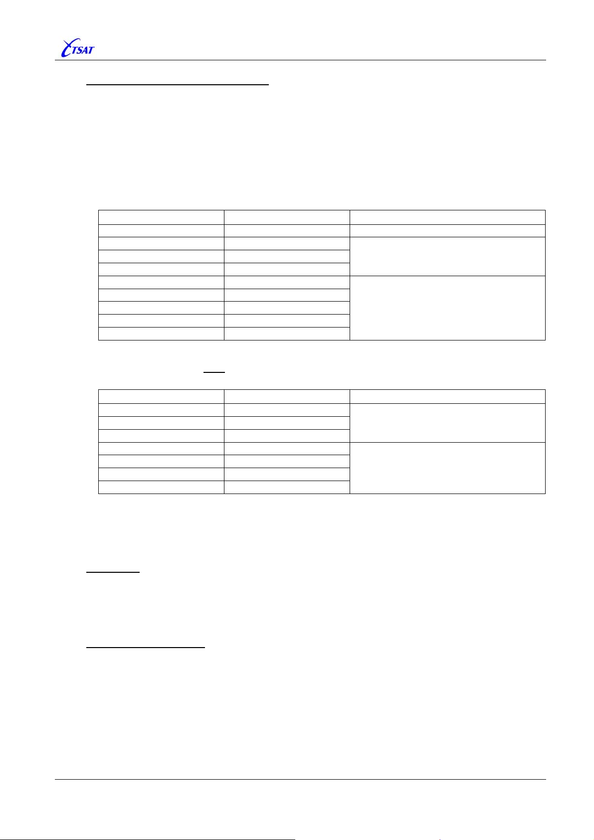
TSAT 3000 - Telemetry and data transfer via SATellite
Configure Connection between HUBs
One or more (redundant) connections may be defined between the Slave- and Master-HUB.
You do this by connecting SERVICE ports together. (The same kind of communication link is
used between Main-HUBs in a Redundant Network configuration) Some examples may clarify:
• Connect with TCP/IP.
Normally, PORT [4] is SERVICE, and is using SOCKET [1]. This is normally a TSAT_NMS
Socket, using TCP/IP and Listening at local IP-port 4000. This Socket is normally used to
connect the NMS to TSAT 3000 Main-Unit, but may also be used to establish connections
between TSAT 3000 Main-Units.
Configure a new Client Socket connection on the Slave-HUB:
MIB Parameter MIB Value Description
PORT_MAX_PORTS 5 (or higher) You probably have to define more Ports.
PORT_TYPE [5] 2 – SERVICE
PORT_USE_SOCKET [5] 2
PORT_USE_COM [5] 0
SOCK_TYPE [2] 2 – TSAT-NMS
SOCK_PROTOCOL [2] 0 – TCP/IP
SOCK_ADDRESS [2] <Master-HUB’s IP Address>
SOCK_LOCAL_PORT [2] 0
SOCK_REMOTE_PORT [2] 4000
PORT [5] is SERVICE,
and is using SOCKET [2]
SOCKET [2] is a TSAT-NMS TCP/IP Client
socket, and will connect to the Server socket
on the Master-HUB.
• Connect with Serial cable.
Configure COM-1 on both
cable.
MIB Parameter MIB Value Description
PORT_TYPE [1] 2 – SERVICE
PORT_USE_SOCKET [1] 0
PORT_USE_COM [1] 1
PORT_BIT_RATE [1] 115200
PORT_DATA_BITS [1] 8
PORT_STOP_BITS [1] 1
PORT_PARITY [1] 0
Master- and Slave-HUB, and connect them together with a serial
PORT [1] is SERVICE, and is using COM [1]
COM [1] is 115200,n,8,1.
Note: The Hub will use NET_RT_ADDRESS to distinguish between the other Hubs, so this MIB
parameter must be set different on all connected Hubs. It’s recommended to use the same
HUB-number as the NMS does (however, any value less than 256 will work ok).
Debugging
Some debug information is issued when you enable bit 8 (0x0100 –
UTL_DEBUG_MASK_B. Two other bits control debugging of the communication link between
Slave- and Master-HUB. That is bit 4 (0x0010 –
DEBUG_H2H_DATA) in UTL_DEBUG_MASK_B.
DEBUG_MIL) in
DEBUG_H2H_CTRL) and bit 5 (0x0020 –
Disable TX Gain Control
Tx Gain control is by default disabled when unit is configured as Slave-HUB. The following
MIBs are set to default values:
• GAIN_TX_OVERRIDE = 1 - Nearly no Tx Gain.
• GAIN_TX_REF = 1.0 - Disable AGC. Don’t ever read the Tx-Detector.
• GAIN_TX_END2END_TARGET = 0 - Disable “End-to-End Tx Gain” facility.
You may later change CURRENT (or FLASH) values, but these default values are
nevertheless applied the next time CCU is restarted.
TSAT 3000 Configuration Parameter Description, January 2013 Page 88 of 124
Page 89
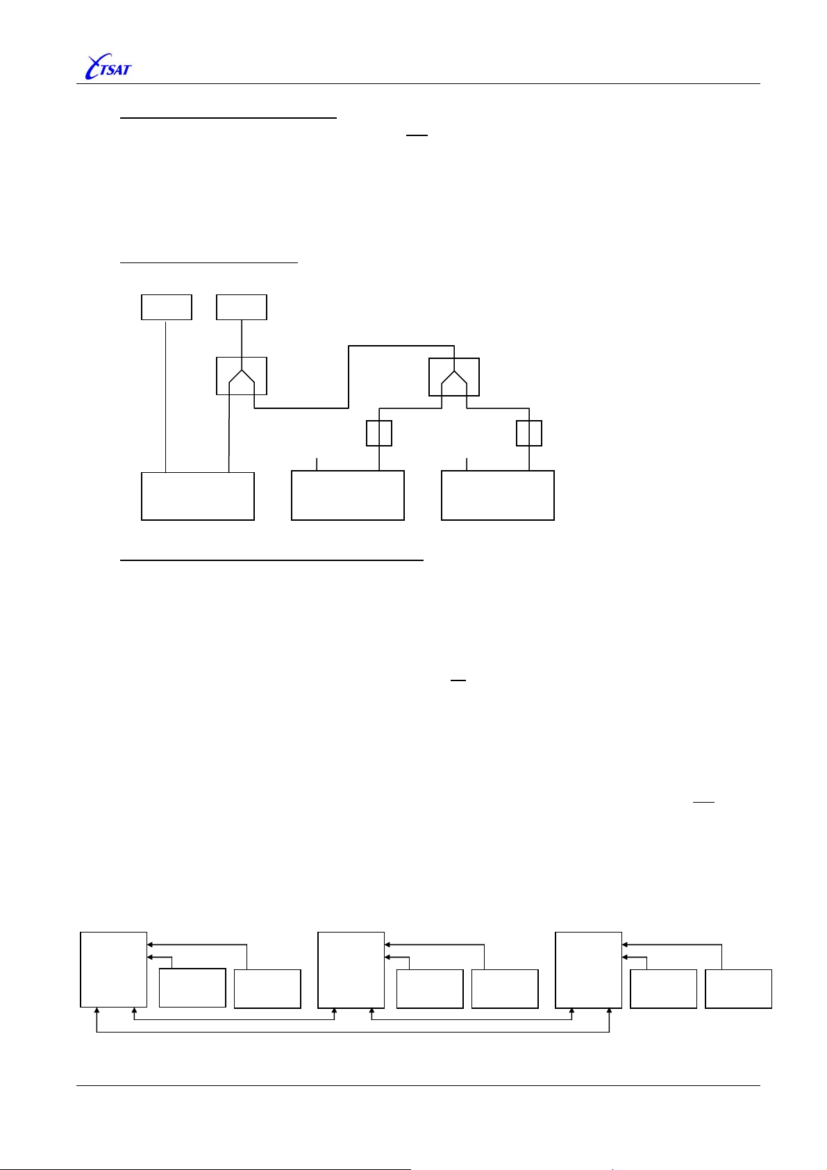
TSAT 3000 - Telemetry and data transfer via SATellite
Configure Hardware – “hw.conf”
The Slave-HUBs should be configured to not
apply Power and 10 MHz reference to BUC and
LNB. Disable (i.e. parameter value “no”) the following parameters in “hw.conf” configuration
file:
• UseBUCPower
• UseBUCRefSignal
• UseLNBPower
• UseLNBRefSignal
• TestRXSwitch
• TestRXVoltageAtStart
• TestRXCurrentAtStart
• TestRXPower
• TestTXSwitch
• TestTXSynth
• TestTXPowerAtStart
• TestTXPower
Connecting BUC and LNB
Signal from LNB is split into maximum 8 (?) Slave-HUBs
BUC LNB
RF Splitter
RF Splitter
DC Block DC Block
TX RX
Master HUB
TX RX
Slave HUB
TX RX
Slave HUB
Redundant Multi Inbound Link (MIL) Network
Configure Redundant MIL network:
• RTs: Define all Backup frequencies:
PHL_TX_HUB_FREQUENCY_BKUP
PHL_TX_RT_FREQUENCY_BKUP
PHL_TX_RT_FREQUENCY_2_BKUP
PHL_{OUTBOUND | INBOUND}_IDENTITY_BKUP
PHL_INBOUND_IDENTITY_2_BKUP
• HUBs: Define communication links between all Master-HUBs (as described above – and
shown below).
Note 1: All Outbound- and Inbound-Identities should be different (as they normally are). RTs
are using these Identities to distinguish between HUBs.
Note 2: When RT is connected to Backup-HUB, it will normally switch back to Main-HUB after
a certain time (defined by
reported UP (Searching-for-RTs or In-Lock-RTs). In Redundant MIL mode, it will not
PHL_SWITCH_BACK_TO_MAIN_HUB) when Main-HUB is
switch
back to Main-HUB unless the Main-Slave-HUB also is reported UP or the Backup-SlaveHUB is DOWN.
Note 3: The RT may also switch between Main- and Backup-HUBs when it detects that the
(current) Slave-HUB is DOWN.
This option is controlled by
PHL_SWITCH_SLAVE_HUB_TIMEOUT.
HUB 1
Master A
Hub 2
Slave A1
Hub 3
Slave A2
HUB 4
Master B
Hub 5
Slave B1
Hub 6
Slave B2
HUB 7
Master C
Hub 8
Slave C1
Hub 9
Slave C2
TSAT 3000 Configuration Parameter Description, January 2013 Page 89 of 124
Page 90

TSAT 3000 - Telemetry and data transfer via SATellite
3.11.23 PHL_TX_RT_FREQUENCY_2_BKUP
Ver <= 30.4.1: Default 0, Range 0 + 14.000.000…14.500.000 – No-Current
Ver >= 30.5.0: Default 0, Range 0 + 5.000.000…14.500.000 – No-Current
Set the Backup Secondary Inbound carrier [kHz] in a Redundant Multi-Inbound-Link (MIL) network.
Ver <= 30.7.0
Not Used.
Ver >= 30.8.0 + RT DSP >= 2.3.1
HUB: Not Used.
RT: The RT TX frequency to Backup-Slave-HUB in kHz. The RT will switch to send to this
Slave-HUB if it cannot open the link to the Main-Master-HUB.
TSAT 3000 Configuration Parameter Description, January 2013 Page 90 of 124
Page 91

TSAT 3000 - Telemetry and data transfer via SATellite
3.11.24 PHL_TX_FREQUENCY_ADJUST
Default 0, Range –10000…+10000
When operating in 2150-Compatibility mode (bit 10 – 0x0400 in UTL_UTILITY_MASK), the
inbound carrier from RTs with different hardware revisions (TSAT 2100, 2150 and 3000), and
different DSP software versions (
received at the HUB at slightly different frequencies. Up to 150 Hz difference has been observed.
This doesn’t cause any problem in homogeneos network with only TSAT 2100, TSAT 2150 or
TSAT 3000. However, in a network with both older and newer hardware and/or DSP software, the
RTs will send at different frequencies, and the HUB will have problem to receive all RTs.
Therfore, we have to slightly adjust the RT’s transmitting frequency.
Ver <= 30.8.0
Not Implemented.
Ver >= 31.0.0
HUB: It’s possible to adjust the HUB’s outbound frequency, but why should you do this?
RT:
PHL_TX_FREQUENCY_ADJUST [Hz] is used to adjust the RT’s inbound frequency.
Note: CCU ver <= 31.8.0 will restart DSP 10 seconds after CURRENT value is changed, when
this option is enabled by bit 2 (0x0004) in
CCU Ver >= 31.8.1 (R4.7.1) will not
changed immediately in DSP Ver >= 3.2.2.
HUB Ver >= 31.1.0
When HUB operate in 2150-Compatibility mode, the Automatic Frequency Adjustment (AFA)
mechanism will adjust the frequency of all TSAT 2100/50 RTs with DSP version >= P22.5.0
(provided option is enabled in RT by bit 23 (0x80.0000) in
Assuming all TSAT 2100/50 RTs are version >= 25.0.0 (and all 3000 RTs >= 31.0.0), AFA
works as follow:
• The RT’s DSP version and HW revision is signaled from RT to HUB in all
packets.
• The HUB will select one of the RTs as reference frequency, and keep this RT as
Reference-RT until link has been reported DOWN (for more than 10 poll-cycles), or a more
prioritized RT is reported UP (i.e. is included in the poll-cycle for more than 10 poll-cycles).
The HUB is selecting the Reference-RT after the following criteria:
1) Preferable the first
TSAT 3000, or 2100 RT with DSP version <= P22.4.0, in poll-cycle is
selected, because such RTs cannot adjust frequency.
2) The first
3) The first
TSAT 2100 RT in poll-cycle.
RT in poll-cycle.
• The frequency adjustment (+/–1 or 2 Hz compared to the Reference-RT) is signaled to each
of the RTs (but not the Reference-RT) in
version >= P22.5.0 are requested to modify their TX frequency.
• Only TSAT 2100/50 RTs with AFA enabled, will actually adjust their TX frequency. The
CURRENT value of PHL_TX_FREQUENCY_ADJUST will be modified (+/–1 or 2 Hz).
However, it cannot be automatically adjusted to a value outside the range (
of
PHL_TX_FREQUENCY_ADJUST) +/–150 Hz.
2100 DSP <= 22.4.0 – 2100/50 DSP >= 22.5.0 – 3000 DSP) are
UTL_UTILITY_MASK.
restart DSP, because PHL_TX_FREQUENCY_ADJUST is
UTL_UTILITY_MASK).
POLL_ACK
SYNC packets. Only TSAT 2100/50 RTs with DSP
EEPROM value
TSAT 3000 Configuration Parameter Description, January 2013 Page 91 of 124
Page 92

TSAT 3000 - Telemetry and data transfer via SATellite
Debugging
A) Messages:
Some debug information is issued when you enable bit 22 or 23 (0xC0.000) in
UTL_DEBUG_MASK_B.
• Bit 22 – 0x40.000 –
• Bit 23 – 0x80.000 –
Use
UTL_DEBUG_RT_ADDRESS to select appropriate RT.
DEBUG_TX_FREQUENCY_ADJUST_RX_2150 – Receiving packet from RT.
DEBUG_TX_FREQUENCY_ADJUST_TX_2150 – Sending freq. adjust to RT.
B) RX Frequency:
Setting
RT defined by
window. The Reference-RT will be selected when
UTL_MIRROR_CHANNEL = 102, will make the average RX frequency received from
UTL_DEBUG_RT_ADDRESS to appear in NMS – ‘Eb/No and Freq. Deviation’
UTL_DEBUG_RT_ADDRESS is zero.
C) Reference-RT:
The HUB will always issue a message when Reference-RT is changed.
You may get/set the current Reference-RT by Text Command “test refrt”. Examples:
• “test ref” - Display current Frequency-Reference-RT.
• “test ref <rt>” - Change current Frequency-Reference-RT.
• “test ref <rt> p” - Change current Frequency-Reference-RT, and keep this settings
forever.
3.11.25 PHL_TX_FREQUENCY_ADJUST_BKUP
Default 0, Range –10000…+10000 – No-Current
Ver <= 30.8.0
Not Implemented.
Ver >= 31.0.0
HUB: Not Used.
RT: The parameter has the same interpretation as
This value is used when the Backup set of frequencies are used.
PHL_TX_FREQUENCY_ADJUST.
TSAT 3000 Configuration Parameter Description, January 2013 Page 92 of 124
Page 93
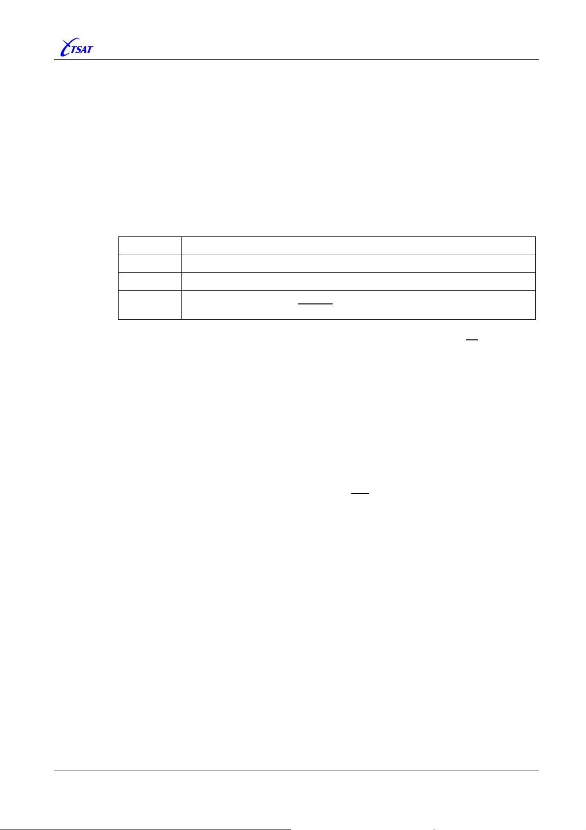
TSAT 3000 - Telemetry and data transfer via SATellite
3.11.26 PHL_SWITCH_BACK_TO_MAIN_HUB
Default 60, Range –1…10080
The “Auto RT Switch-Back to Main Hub” function is controlled by an option in NMS ‘Network
Behaviour’ window. This parameter controls the RT behaviour when this option is enabled.
Ver == 30.0.0
Not Implemented.
Ver >= 30.1.0
HUB: Not used.
RT: Used when Backup-HUB is defined (i.e.
Value Description
–1 Disable “Auto Switch-Back to Main Hub” at this RT.
0 Immediately Switch-Back to Main-HUB when it’s reported operational.
1 … 1440
Wait specified number of minutes
doing a Switch-Back to Main-HUB.
Note: The “Auto RT Switch-Back to Main Hub” option in NMS will have no effect when
two or more HUBs are connected directly to each other.
The RT will always switch to Backup- or Main-HUB when it has received garbled
packets from current HUB for more than
In addition, a MIL-RT will also switch when current Slave-HUB has been reported
DOWN for more than
PHL_SWITCH_SLAVE_HUB_TIMEOUT [seconds].
A Non-MIL-RT will switch back to Main-HUB after
[minutes], if Main-HUB is reported operational at that point of time.
Similarly, the MIL-RT will switch back to Main-HUB after
MAIN_HUB
[minutes], if Main-Master-HUB and Main-Slave-HUB are reported
operational at that point of time.
PHL_TX_HUB_FREQUENCY_BKUP > 0).
(after first Link Open to Backup-HUB) before
NET_MAX_POLL_SECONDS [seconds].
PHL_SWITCH_BACK_TO_MAIN_HUB
PHL_SWITCH_BACK_TO_
See also
PORT_SWITCH_TIMEOUT [n].
TSAT 3000 Configuration Parameter Description, January 2013 Page 93 of 124
Page 94
TSAT 3000 - Telemetry and data transfer via SATellite
3.11.27 PHL_SWITCH_SLAVE_HUB_TIMEOUT
Default 60, Range –1…86400
In a Redundant Multi Inbound Link (MIL) network, the RT may also switch between Main- and
Backup-HUBs when it detects that the (current) Slave-HUB is DOWN. This function is controlled
by this parameter.
Ver <= 30.7.0
Not Implemented.
Ver >= 30.8.0
HUB: Not used.
RT: Used when Backup-Slave-HUB is defined (i.e.
PHL_TX_RT_FREQUENCY_2_BKUP > 0).
Value Description
–1 Do NOT switchover when Slave-HUB is DOWN.
0
1 … 86400
TEST. Immediately switching when Current Slave-HUB is reported DOWN,
and both the Other Main- and Slave-HUBs are
Wait until the Current Slave-HUB has been DOWN the specified time
[seconds], and the RT has been told so (by the Current Master-HUB) at least
twice. Then do switch-over when both the Other Main- and Slave-HUBs are
OPERATIONAL.
Note: The term OPERATIONAL will normally mean that both the Other Main- and Slave-
HUBs are In-Lock-RTs. However, you may alter this default behavior by enable bit
3 (0x0008 –
enabled, the term
UTILITY_SLAVE_HUB_SWITCHING) in UTL_UTILITY_MASK. When
OPERATIONAL will mean that both the Other Main- and Slave-
HUBs are Searching-for-RTs, Emergency-Polling or
See also
PORT_SWITCH_TIMEOUT [n].
PHL_TX_HUB_FREQUENCY_BKUP and
OPERATIONAL.
In-Lock-RTs.
TSAT 3000 Configuration Parameter Description, January 2013 Page 94 of 124
Page 95

TSAT 3000 - Telemetry and data transfer via SATellite
3.11.28 PHL_DELTA_SEARCH_FREQUENCY
Ver <= 30.5.0: Default 60, Range 10…1000
Ver >= 30.6.0: Default 0, Range 0 + 10…1000
Half the frequency search range, expressed in kHz.
The frequency search range should at least be some kHz larger than occupied bandwidth.
On an RT,
INBOUND}_FILTERALFA
PHL_{OUTBOUND | INBOUND}_SYMBOLRATE x ( 1 + PHL_{OUTBOUND |
) / 1000 will normally be a useable value.
Example: Symbol-Rate 64 kbps + Filter-Alfa 0.3 = 64 x 1.3 = 83 kHz.
Ver == 30.6.0 … 30.7.0
When parameter value is zero, the frequency search range will be calculated as shown by the
formula above.
Ver >= 30.8.0
When parameter value is zero, the frequency search range will be calculated as shown by the
formula above + 5 kHz. This could be necessary when TCXO calibration is out-of-range and
Symbol-Rate is very low (16 kbps).
TSAT 3000 Configuration Parameter Description, January 2013 Page 95 of 124
Page 96
TSAT 3000 - Telemetry and data transfer via SATellite
3.11.29 PHL_SAT_CONVERT_FREQUENCY
Ver <= 30.4.1: Default 1.500.000, Range 500.000…5.000.000
Ver >= 30.5.0: Default 1.500.000, Range 1.000.000…5.000.000
Set the satellite conversion frequency [kHz]. The MIB value must match the used satellite.
Typically values are 1.500.000 or 2.800.000 [kHz]
Note: DSP will be restarted 10 seconds after you’ve changed CURRENT value.
Ver >= 30.8.0: Restart of DSP is enabled by bit 2 (0x0004) in
UTL_UTILITY_MASK.
3.11.30 PHL_FE_RX_LO
Ver <= 30.4.1: Default 11.300.000, Range 5.000.000…20.000.000
Ver >= 30.5.0: Default 11.300.000, Range 2.000.000…16.000.000
Set the RX (LNB) Local Oscillator frequency [kHz]. The MIB value must match the connected
LNB. Currently the following LNBs are used with TSAT 3000 Main Unit:
LNB – TSAT Part No
PHL_FE_RX_LO
[kHz]
RX 1410 A 11.300.000
RX 1410 B 10.000.000
RX 1410 C 10.750.000
Note: DSP will be restarted 10 seconds after you’ve changed CURRENT value.
Ver >= 30.8.0: Restart of DSP is enabled by bit 2 (0x0004) in
UTL_UTILITY_MASK.
3.11.31 PHL_FE_TX_LO
Ver <= 30.4.1: Default 13.050.000, Range 5.000.000…20.000.000
Ver >= 30.5.0: Default 13.050.000, Range 2.000.000…16.000.000
Set the TX (BUC) Local Oscillator frequency [kHz]. The MIB value must match the connected
BUC. Currently the following BUC is used with TSAT 3000 Main Unit:
BUC – TSAT Part No
TX 1414 C 13.050.000
PHL_FE_RX_LO
Note: DSP will be restarted 10 seconds after you’ve changed CURRENT value.
Ver >= 30.8.0: Restart of DSP is enabled by bit 2 (0x0004) in
[kHz]
UTL_UTILITY_MASK.
TSAT 3000 Configuration Parameter Description, January 2013 Page 96 of 124
Page 97

TSAT 3000 - Telemetry and data transfer via SATellite
3.12 PACKET PARAMETERS
3.12.1 PKT_MAX_SIZE
Ver <= 30.3.1: Default 256, Range 100…2100 – BOOT
Ver >= 30.4.0: Default 256, Range 256…2100 – BOOT
Set the size of the CCU’s internal packet structure, and must at least be 60 bytes larger than
PKT_OUTBOUND_SIZE (which defines the actual satellite Link packet size).
Note: Due to an error in ver 30.3.0 & 30.3.1, PKT_MAX_SIZE must be >= 336 bytes in such units.
3.12.2 PKT_OUTBOUND_SIZE
Default 60, Range 28…2040
Set the number of bytes in a satellite Link packet from HUB to RT. It should at least be greater or
equal 28 bytes, due to the size of
Note: When PPR is enabled, the minimum PKT_OUTBOUND_SIZE is increased:
• 30 bytes when
• 31 bytes when
See
PHL_SLOT_PHASE_MODE.
PPR_PULSES = 2…8
PPR_PULSES = 9…15
Note: DSP will be restarted 10 seconds after you’ve changed CURRENT value.
Ver >= 30.8.0: Restart of DSP is enabled by bit 2 (0x0004) in
SYNC packets.
UTL_UTILITY_MASK.
TSAT 3000 Configuration Parameter Description, January 2013 Page 97 of 124
Page 98

TSAT 3000 - Telemetry and data transfer via SATellite
3.12.3 PKT_INBOUND_SIZE
Read-Only
Read the number of bytes in a satellite Link packet from RT to HUB. It is calculated after the
restart of the Main Unit (and when any of DSP configuration parameters are changed), and is a
function of:
• PKT_OUTBOUND_SIZE
•
PHL_{OUTBOUND | INBOUND}_SYMBOLRATE
PHL_{OUTBOUND | INBOUND}_FECRATE
•
PHL_IN_OUT_PACKET_RATIO
•
PHL_INBOUND_GUARDPERIOD
•
PHL_SLOT_PHASE_MODE
•
PKT_INBOUND_SIZE should at least be greater or equal:
• Ver <= 30.1.1: 16 bytes, due to the size of
• Ver == 30.2.0…30.3.1: 24 bytes, due to the size of
Note: The Link will still work OK with
information in the
from RT to HUB. See
POLL_ACK packet will be lost. That is GROUP information signalled
PORT_STREAM_RT [n].
• Ver >= 30.4.0: 26 bytes, due to the size of
Note: The Link will still work OK with
versions do), but the HUB will not
POLL_ACK packet. “IP Routed Line”, “IP Outbound Secure Link” and “IP Redundancy
Facility” will be disabled. See
PORT_STREAM_RT [n] and PORT_MAX_APPL_RETRIES [n].
• Ver >= 31.0.0: 27 bytes, due to the size of
Note: The Link will still work OK with
versions do), but the HUB will not
POLL_ACK packet. This will affect the “Robust Header Compression (ROHC) Facility”
implemented in VxWorks 6.7 (Release 4.x.x).
POLL_ACK, LINK_RESET and LINK_ACK packets.
POLL_ACK packets.
PKT_INBOUND_SIZE as low as 16 bytes, but some
POLL_ACK packets.
PKT_INBOUND_SIZE less than 26 bytes (as older
be able to fetch the RT’s Satellite IP address from the
POLL_ACK packets.
PKT_INBOUND_SIZE less than 27 bytes (as older
be able to fetch the RT’s IP-Link-Options from the
A WARNING will be issued when it’s calculated to be less than minimum number of bytes.
3.12.4 PKT_POOL_SIZE
Default 300, Range 100…1000 – BOOT
Set the number of available packets in the CCU. It may cause loss of data if set too small.
TSAT 3000 Configuration Parameter Description, January 2013 Page 98 of 124
Page 99

TSAT 3000 - Telemetry and data transfer via SATellite
3.13 POWER PARAMETERS
Power-Save functions are implemented in Ver >= 31.1.0. By use of these functions, the RT may
save a lot of power. Typical example with 2W Zinwell Ku-band BUC:
• Normal operation: 1.78 A @ 24 V = 43 W
• Listen mode – 10MHz: 1.25 A @ 24 V = 30 W
• Listen mode – Power: 1.09 A @ 24 V = 26 W
• Sleep mode: 0.45 A @ 24 V = 11 W
LISTEN Mode
The BUC is normally turned OFF, and will be turned ON when RT has something to send. You can
select to turn off 10 MHz and/or Power to the BUC.
- Switching 10 MHz is fast (less than 1 ms), but RT will consume more power.
- Switching Power consume less power, but it take longer time (approx 50 ms – one or more slots)
to turn on the BUC. Also, turning Power on/off could make disturbance to the receiver, and RT will
normally receive 1 or 2 CRC errors when Power is turned ON. Sometimes also a single CRC error
when Power is turned OFF.
In addition, RT may be excluded from the normal circular polling scheme, to decrease the time BUC
has to be ON.
RT will consume maximal Power when BUC is turned ON. Therefore, total Power consumption will
be something between 26 and 43 W, depending on how much data that is sent from RT to HUB.
LISTEN mode is configured by the following MIB parameters:
- POW_LISTEN_HPA_MODE
POW_LISTEN_HPA_ON
-
POW_LISTEN_HPA_OFF
-
POW_LISTEN_POLL
-
SLEEP Mode
Power to BUC, LNB, TX-board and RX-board are turned OFF – Only Main-board is alive, and unit
(HUB or RT) consumes minimum Power (11 W). Sleep mode may be activated:
- by Connected Application (DTR or CTS input signals).
- at Regular Intervals.
- by NMS Operator.
SLEEP mode is configured by the following MIB parameters:
- POW_WAKEUP_FIRST_TIME
POW_WAKEUP_INTERVAL
-
POW_LINK_UP_DURATION
-
COM_SIGNAL_IN [n]
-
TSAT 3000 Configuration Parameter Description, January 2013 Page 99 of 124
Page 100
TSAT 3000 - Telemetry and data transfer via SATellite
3.13.1 POW_WAKEUP_FIRST_TIME
Ver <= 31.0.1: Default 0, Range –1… 1440
Ver >= 31.1.0: Default 0, Range 0…10080
Ver <= 31.0.1
Not Used.
Ver >= 31.1.0
Controls SLEEP mode operation.
Used when the Main-Unit Power-Save function is enabled by POW_WAKEUP_INTERVAL >= 2.
To let the different RTs wake up to specified time(s) relative to NMS, HUB and RT real time,
this MIB variable will define the first
(that is: 1 minute … 1 week). Some examples:
POW_WAKEUP_
FIRST_TIME
POW_WAKEUP_
INTERVAL
12 60 00:12 – 01:12 – 02:12 - - - 23:12
10 10 00:10 – 00:20 – 00:40 - - - 23:50
1 70 00:01 – 01:11 – 02:21 - - - 23:21
720 1440 12:00 – 12:00 (next day)
3605 10080 Wednesday 12:05 – Wednesday 12:05 (next week)
Default value 0 will make the CURRENT to be replaced by 60 x 12 + NET_RT_ADDRESS – 1.
That will make all RTs to wake up at different
- RT 1 will wake up 12:00
- RT 2 will wake up 12:01
- RT 40 will wake up 12:39
time Main-Unit is waked up. Range is 0…10080 [minutes]
Main-Unit is waked up [hh:mm]
times the first time:
TSAT 3000 Configuration Parameter Description, January 2013 Page 100 of 124
 Loading...