

APOLLO OPERATING MANUAL
___________________________________________________________________________________
_______________________________________________________________________________________
TSAKIRIDIS DEVICES - TUBE AUDIO AMPLIFIERS
Operating manual
Apollo ‘plus’
reference
monoblock power amplifier
APOLLO OPERATING MANUAL
_______________________________________________________________________________________
______________________________________________________________________________
TSAKIRIDIS DEVICES - TUBE AUDIO AMPLIFIERS
©2009
All rights reserved
TSAKIRIDIS DEVICES
AUDIO AMPLIFIERS
Aristomenous 12 Str,
T.K. 10440, Athens, GREECE
Tel: 210 8253132 / Fax: 210 8253794
info@tsakiridis-devices.com
www.tsakiridis-devices.com
Distributed in the
UK & Ireland
by
ikon audio consultants
www.ikonaudioconsultants.com
info@ikonaudioconsultants.com
APOLLO OPERATING MANUAL
_______________________________________________________________________________________
______________________________________________________________________________
TSAKIRIDIS DEVICES - TUBE AUDIO AMPLIFIERS
©2009
All rights reserved
Declaration of Conformity
Tsakiridis Devices
Aristomenous 12 Str,
T.K. 10440
Athens,
GREECE
Declare that the product described in this owner’s manual is compliant with the
technical standards:
EMISSIONS EN 55103-1:1997
IMMUNITY EN55103-2:1997
Tests Procedure
Voltage Dips, Interruptions EN61000-4-11: 1994
Harmonics EN61000-3-2: 2000
Surge EN61000-4-5: 1995
Conducted Emissions EN55022: 1998
Radiated Emissions EN55022: 1998
ESD EN61000-4-2: 1995
Conducted Immunity EN61000-4-6: 1996
Radiated Immunity EN61000-4-4: 2004
EFT EN61000-4-4: 2004
Flicker EN6100-3-3: 1995
Dr. Tsakiridis Odysseus
Tsakiridis Devices
10/2006
APOLLO OPERATING MANUAL
_______________________________________________________________________________________
______________________________________________________________________________
TSAKIRIDIS DEVICES - TUBE AUDIO AMPLIFIERS
©2009
All rights reserved
Contents
1. Introduction
2. Installation
3. Special Notice
4. Amplifier Top
5. Amplifier Back
6. Warranty
7. Specifications
8. Re-biasing Procedure
APOLLO OPERATING MANUAL
_______________________________________________________________________________________
______________________________________________________________________________
TSAKIRIDIS DEVICES - TUBE AUDIO AMPLIFIERS
©2009
All rights reserved
1.Introduction
Thank you for your purchase of this TSAKIRIDIS DEVICES Apollo amplifier.
We are very proud of our products and feel sure that it will bring you many years of audio
pleasure and that like other high quality audio products, it will be a valued possession for
you and for future generations of music lovers.
Welcome to the Apollo Amplifier! This manual introduces you to its key features, and
explains how you can take advantage of its superb sound in your system. Please retain
this book for reference.

APOLLO OPERATING MANUAL
_______________________________________________________________________________________
______________________________________________________________________________
TSAKIRIDIS DEVICES - TUBE AUDIO AMPLIFIERS
©2009
All rights reserved
2. Connection and Installation
• To prevent fire or shock hazard, do not expose this unit to rain or moisture.
• Dangerous voltages inside. Do not open the amplifier cabinets. There are no user
serviceable parts inside. Repairs should be carried out by qualified service
personnel only.
• Take care to handle the power cord carefully and not to crimp or damage it as this
can cause electric shock or damage the device.
• Do not insert any objects into the amplifier.
• To install the device, select an open place with good ventilation. The amplifier
should be placed so that the valves (vacuum tubes) are always vertical.
• The amplifier operates with alternating current voltage 240 VOLT, 50 HZ. Before
connecting power check that the required supply voltage corresponds to your local
AC supply. If a different voltage is stated, do not connect the amplifier to the mains
power, and seek advice from your dealer / distributor.
• Never pull the power cable from the cord.
• Connect to the mains power using a high quality mains cable.
• Always disconnect the amplifier from the mains power before connecting or
disconnecting any of the input or loudspeaker cables.
• Never expose the device directly to the sun or attempt to operate it outdoors.
• Do not place the amplifier near radiators or other sources of heat and generally
avoid placing the device in an adverse environment.
• All valve amplifiers need time to reach their optimal operating temperature. We
recommend, therefore, that you allow at least fifteen minutes for the amplifiers to
‘warm up’ before use. Warming up should be done with the volume control (on the
pre amplifier) set to zero, with no signal passing to the power amplifier.

APOLLO OPERATING MANUAL
_______________________________________________________________________________________
______________________________________________________________________________
TSAKIRIDIS DEVICES - TUBE AUDIO AMPLIFIERS
©2009
All rights reserved
3. Special Notice
Do not place the amplifier near each other while in operation because the
magnetic field emitted from the power supply can cause noise and adversely
affect audio playback quality.
Never change the position of the amplifiers during operation and wait for 20
minutes after powering off before moving, because of the high voltages that
remain in the amplifier.
Do not touch the valves during operation – serious risk of being burned!
The lifetime of the tube is 7,000 hours for Apollo and after this time replacement is
necessary.
After use, always allow the amplifiers to cool down before re-starting (2 minutes
should suffice).
Do not operate the amplifier without a load (speaker cables attached) as this can
cause damage to the amplifiers.

APOLLO OPERATING MANUAL
_______________________________________________________________________________________
______________________________________________________________________________
TSAKIRIDIS DEVICES - TUBE AUDIO AMPLIFIERS
©2009
All rights reserved
4. Amplifier Top
• On the top and front of the amp there are two switches.
• The left switch selects the percentage of feedback. In the rear position (the switch is
nearest to the transformers) allows low feedback and the front position (the switch is
furthest from the transformers) is normal feedback.
• The right switch chooses the operating mode of the pair of output tubes. In the rear
position (the switch is nearest to the transformers) the output tubes operate at triode
operation and in the front position (the switch is furthest from the transformers) they
operating at 50% triode and 50% pentode mode (Ultra linear).

APOLLO OPERATING MANUAL
_______________________________________________________________________________________
______________________________________________________________________________
TSAKIRIDIS DEVICES - TUBE AUDIO AMPLIFIERS
©2009
All rights reserved
5. Amplifier Rear
• The ON/OFF switch is at the rear.
• Connections (inputs and outputs) are at the rear of the amplifier.
• Always disconnect the amplifier from the mains power before connecting or
disconnecting any of the inputs or loudspeaker cables.
• Use the best possible quality input cables and loudspeakers interconnect cables.
Please consult your dealer or distributor for advice.
• See diagram on the following page.

APOLLO OPERATING MANUAL
_______________________________________________________________________________________
______________________________________________________________________________
TSAKIRIDIS DEVICES - TUBE AUDIO AMPLIFIERS
©2009
All rights reserved

APOLLO OPERATING MANUAL
_______________________________________________________________________________________
______________________________________________________________________________
TSAKIRIDIS DEVICES - TUBE AUDIO AMPLIFIERS
©2009
All rights reserved
6.
Warranty
TSAKIRIDIS DEVICES offers a five-year (5) warranty for all its appliances from the date
of purchase. (proof of purchase will be required, so please retain your receipt).
Technical support is provided by the manufacturer, however if you require support for
your product, in the first instance please contact your reseller or distributor to explain the
symptoms. They will advise on the best course of action.
If the amplifier needs to be returned for service or repair, please use the original carton
provided. Please include a note detailing your name, address, your phone and a brief
description of you symptom and events surrounding the malfunction / complication.
Type: Apollo
Serial number:
Surname:
Name:
Address:
Location:
Postal Code:
Email:
Phone number:
Date and place of Purchase:
We advise owners to retain al the packaging throughout the lifetime of the product – it
should be used when / if moving home and returning products for service / repair.
Please note that unauthorised alterations or modifications will invalidate the warranty.
This warranty does not include the valves which are subject to wear as discussed
above.
All transport costs for warranty items is to be borne by the customer and is not the
responsibility of the manufacturer or distributor. Please consult the distributor in case of
uncertainty.
In the event that damage has been caused to the amplifier which falls outside of the
terms of this warranty, from deliberate or unintended case of intervention by third parties
shall cease to apply security and the holder shall bear the costs of parts and labour.
APOLLO OPERATING MANUAL
_______________________________________________________________________________________
______________________________________________________________________________
TSAKIRIDIS DEVICES - TUBE AUDIO AMPLIFIERS
©2009
All rights reserved
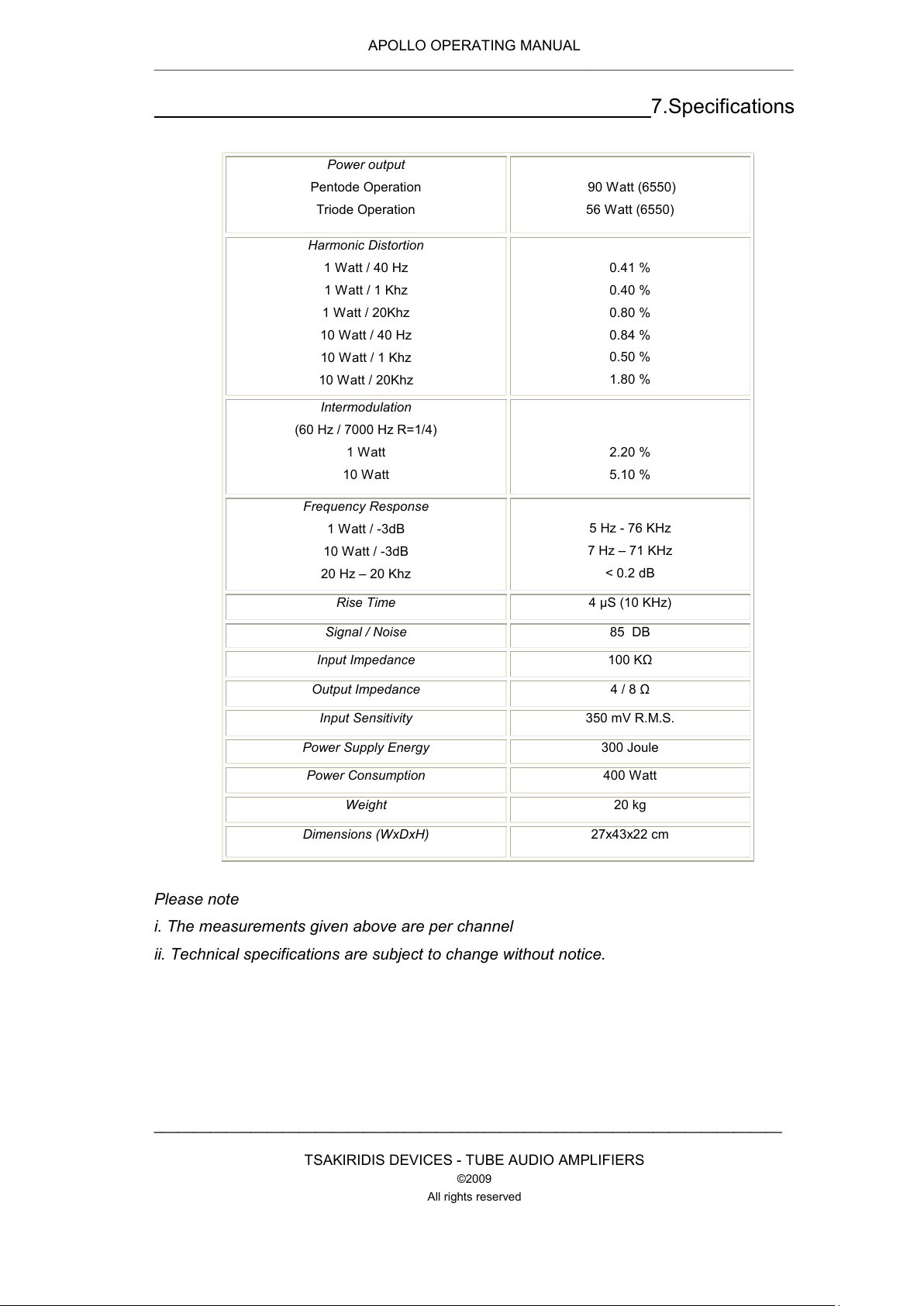
7.Specifications
Power output
Pentode Operation
Triode Operation
90 Watt (6550)
56 Watt (6550)
Harmonic Distortion
1 Watt / 40 Hz
1 Watt / 1 Khz
1 Watt / 20Khz
10 Watt / 40 Hz
10 Watt / 1 Khz
10 Watt / 20Khz
0.41 %
0.40 %
0.80 %
0.84 %
0.50 %
1.80 %
Intermodulation
(60 Hz / 7000 Hz R=1/4)
1 Watt
10 Watt
2.20 %
5.10 %
Frequency Response
1 Watt / -3dB
10 Watt / -3dB
20 Hz – 20 Khz
5 Hz - 76 KHz
7 Hz – 71 KHz
< 0.2 dB
Rise Time 4 µS (10 KHz)
Signal / Noise 85 DB
Input Impedance 100 ΚΩ
Output Impedance 4 / 8 Ω
Input Sensitivity 350 mV R.M.S.
Power Supply Energy 300 Joule
Power Consumption 400 Watt
Weight 20 kg
Dimensions (WxDxH) 27x43x22 cm
Please note
i. The measurements given above are per channel
ii. Technical specifications are subject to change without notice.

APOLLO OPERATING MANUAL
_______________________________________________________________________________________
______________________________________________________________________________
TSAKIRIDIS DEVICES - TUBE AUDIO AMPLIFIERS
©2009
All rights reserved
8. Re-biasing procedure
This procedure is required when changing or replacing the valves.
Required instruments:
1. A multimeter capable of measuring direct voltage level to approximately 300m.V.
D.C.
2. Ohmic load approximately 8 OHM / 10 WATT (can be used and the speakers,
subject)
3. A small plastic screwdriver - straight.
Set-up process
Connect the amplifier to be configured with ohmic load (no polarity) or the
speaker).
Connect the line input of the amplifier to the preamp, but switch off the preamp.
Connect the negative pole of the multimeter to the black connector of the speaker
output (-) and red leave for an hour incoherent.
Activate the amplifier (CAUTION are deadly currents during operation of the
amplifier, which persist even after the power supply from the network).
Take the red probe (of the multimeter) and place in binding post behind the tube
we want to regulate.
Measure the voltage, the indication must be 200 mV + / - 10 m.V. for the EL 34
and 250 m.V. + / - 10 mV for KT88 or KT 6550 as we increase the idling current as
the amplifier goes from class AB to class A, but with reduced life without audible

APOLLO OPERATING MANUAL
_______________________________________________________________________________________
______________________________________________________________________________
TSAKIRIDIS DEVICES - TUBE AUDIO AMPLIFIERS
©2009
All rights reserved
improvement. Since the laboratory is adjusted in the Apollo 200 mV which
translates into a cathode current 20 mA.
Repeat for each Monoblock unit.
I = U/R
where:
I is the cathode current in mA
U is the voltage measured with the multimeter to mV
R is the resistance of cathode (the Appolo amplifier is 10 OHM).
Adjust the current of each tube with the plastic screwdriver the corresponding
variable resistor (trimmer) located right or left respectively.
Waiting 5-10 minutes and repeat the above two steps, if necessary make a
adjustments.
The setup process is finished.
CAUTION
Very high levels of electrical current operate inside the amplifier, which may
continue for many hours after the power supply is disconnected from the mains.
CAUTION
Only trained personnel should open and service this amplifier.
 Loading...