

Page 1

1
MANUAL DEL USUARIO / USER’S MANUAL
HARD series: AX-212TR
TSA. Subject to change without notice.
Manufactured by TSA. / Polígono Alcodar / Carrer Dels musics nº 3 / 46701 Gandia– Valencia (Spain)
Tl: (34) 96 286 8985 / http://www.tsa-sound.com / E.mail: [email protected]
Page 2
2
MANUAL DEL USUARIO / USER’S MANUAL
HARD series: AX-212TR
TSA. Subject to change without notice.
Introducción
El nuevo y mejorado sistema line array de 3 vías AX-212TR ofrece
una respuesta clara y profunda para aplicaciones en las que se
requiere un alto rendimiento. Este sistema se utiliza en combinación
con el sistema de subgraves SB-218LX para aplicaciones de gran
formato, como giras, estadios o grandes instalaciones fijas.
Cada recinto incorpora dos transductores de neodimio de 12
pulgadas con tecnología de refrigeración que ofrece graves
contundentes y limpios con alto aguante de potencia sin que esto
suponga pérdidas de rendimiento. Para las frecuencias medias
utiliza 4 transductores de 6.5 pulgadas que aportan gran claridad y
transparencia. También presenta un exclusivo diseño de guía de
ondas doble de 1,4 pulgadas optimizado para 2 motores de
compresión de neodimio con bobina de 2.9 pulgadas, que ofrece
una reproducción de las altas frecuencias amplia y brillante con baja
distorsión, incluso a grandes distancias de escucha.
La apertura vertical máxima entre unidades es variable hasta 10
grados. Para facilitar el montaje, AX-212TR incorpora un
mecanismo doble que utiliza una fijación variable, que oscila entre 0
y 10 grados con una fijación deslizante y otra fija. El sistema Flying
Frame CHSE212TR utiliza el mismo mecanismo de regulación que
las unidades. Además, se ofrece una plataforma móvil de transporte
(CHST212TR) para almacenar, transportar y apilar los recintos de
forma cómoda y manejable.
Precauciones de Seguridad
El signo de exclamación dentro de un triángulo indica la
existencia de componentes internos cuyo reemplazo puede
afectar a la seguridad. Las especificaciones se encuentran
en la etiqueta de la parte posterior del producto.
Este símbolo indica que el presente producto no puede ser
tratado como residuo doméstico normal, sino que debe
entregarse en el correspondiente punto de recogida de
equipos eléctricos y electrónicos.
El doble recuadro indica que es un equipo Clase II.
No exponga este equipo a lluvia o humedad.
No emplace altavoces en proximidad a equipos sensibles a
campos magnéticos, tales como monitores de televisión o
material magnético de almacenamiento de datos.
Garantía
Todos nuestros productos están garantizados por un periodo de 24
meses desde la fecha de compra. Las garantías sólo serán válidas
si son por un defecto de fabricación y en ningún caso por un uso
incorrecto del producto. La reparación en garantía cubre la
reposición de las partes defectuosas. Otros cargos como portes y
seguros, son a cargo del comprador en todos los casos.
Para solicitar reparación en garantía es imprescindible que el
producto no haya sido previamente manipulado e incluir una
fotocopia de la factura de compra.
Conexiones
Estos modelos utilizan dos conectores Neutrik Speakon NL4,
específicos para altavoces y permiten una conexión profesional.
Para enchufar un cable a una caja, inserte el
conector macho en cualquiera de las
entradas de la caja y gire el conector macho
hacia la derecha, momento en el que quedará
bloqueado. Los dos conectores están en
paralelo (todos los pines), de forma que
cualquiera de ellos puede usarse
indistintamente como entrada o salida.
Introduction
New and improved AX-212TR 3-way line source offers a
clear and deep response for applications where high
performance is required. This system is used in
combination with SB-218LX subwoofer system for large
format applications such as touring, stadiums or fixed
installation.
Each array element incorporates 2x12-inch neodymium
transducers with cooling technology which offers powerful
and clean high power bass without performance losses and
4x6.5-inch transducers for the mid frequencies for total
clarity and transparency. It also features a exclusive double
1.4-inch waveguide design optimized for 2 neodymium
compression drivers with 2.9-inch voice coil, offering broad
and bright high frequencies reproduction with low distortion,
even at large listening distances.
The maximum vertical opening between units is 10
degrees. To facilitate the assembly, AX-212TR incorporates
a double mechanism that uses a variable fixation, which
oscillates between 0-10 degrees as a sliding and fixed
positioning. The Flying Frame System CHSE212TR uses
the same regulation mechanism as the units. In addition, a
transport dolly (CHST212TR) is offered to store, transport
and stack the AX-212TR cabinets.
Safety Precautions
The exclamation point inside an equilateral triangle
indicates the existence of internal components whose
substitution may affect safety. The specifications can be
found on the rear label of the product.
This symbol on the product indicates that this product
should not be treated as household waste.
Instead it shall be handed over to the applicable collection
point for the recycling of electrical and electronic equipment.
The double square indicates Class II device. Do not expose
to rain or moisture.
Do not place loudspeakers in proximity to devices sensitive
to magnetic fields such as television monitors or data
storage magnetic material.
Warranty
All products are warranted against any manufacturing
defect for a period of 2 years from date of purchase.
The warranty ex-cludes damage from incorrect or misuse
use of the product. All warranty repairs must be exclusively
undertaken by the factory or any of its authorized service
centres. To claim a warranty repair, do not open or intend to
repair the product.
Return the damaged unit, at shippers risk and freight
prepaid, to the nearest service centre with a copy of the
purchase invoice.
Connections
The units comprise two Neutrik Speakon model NL4
connectors, designed specifically for loudspeakers, are
used to ensure both professional and safe connection. To
plug a cable into a unit, insert the
male plug into any of the enclosure's
sockets and turn the male plug to the
right so that it is locked. The two
connectors are in parallel (all pins)
so that either one of them can be
used for input or output.
Manufactured by TSA. / Polígono Alcodar / Carrer Dels musics nº 3 / 46701 Gandia– Valencia (Spain)
Tl: (34) 96 286 8985 / http://www.tsa-sound.com / E.mail: [email protected]
Page 3
3
MANUAL DEL USUARIO / USER’S MANUAL
HARD series: AX-212TR
TSA. Subject to change without notice.
Connections
Pin +
1
Pin -1
Pin +
2
Pin -2
Pin +
3
Pin -3
Pin +
4
Pin -4
8 ohms.
700 W
.
8 ohms.
700 W
.
8 ohms.
500 W
.
16 ohms
.
140 W
.
2 x NL8
PARALLE
L
Technical data
Usable bandwidth (-10dB) 38 - 20.000 Hz
Maximum SPL (*) 146 dB (preset)
Horizontal Coverage angle: 80° symmetric (-6 dB points)
Vertical Coverage angle: Depends of the array elements and curvature
Transducers LF: 2 x 12’’ Neodymium LF woofer
Transducers MF: 4 x 6,5’’ MF woofer
Transducers HF: 2 x 1,4’’ Neodymium compression driver with 2.9’’ voice coil
Nominal impedance: LF1: 8 Ω / LF2: 8 Ω / MF: 8 Ω / HF:16 Ω
AES power handling: LF1: 700 W / LF2: 700 W / MF: 1000 W / HF:140 W
Connectors: 2 x NL8
Rigging components: 4-point rigging system
Permissible flown load: 22 units (2-points)
Inter-enclosure angles (degrees): 0 / 0.25 / 1 / 2 / 3 / 4 / 5 / 6 / 7 / 8 / 9 / 10
Physical data
W x H/h x D: 1186 x 380/303 x 558 mm
Weight (net): 71 kg.
Cabinet: First grade Baltic birch plywood
Side panels: Steel rigging hardware
Finish: High resistance rough black paint
Front Steel grill: Steel grid with anti-corrosion coating and foam
Rigging components: High grade steel with anti-corrosion coating
(*) Peak level at 1 m under free field conditions using 10 dB crest factor pink noise with specified preset.
Dimensions
Page 4
4
MANUAL DEL USUARIO / USER’S MANUAL
HARD series: AX-212TR
TSA. Subject to change without notice.
Montaje de un cluster de tres unidades
El clúster puede ser montado de manera fácil: El AX-212TR
monta un aparejo de reglaje, que determina ángulo vertical
entre las unidades, este aparejo incorpora una fijación
variable a modo de corredera que oscila entre 0º y 10º,
para facilitar el trabajo del operario, (Ver figura 6). El
aparejo de volado (CHSE212TR) y la base con ruedas
(CHST212TR), utilizan el mismo mecanismo de reglaje que
las El AX-212TR , (Ver figura 7).
Instrucciones de montaje:
1. Se deposita la base con ruedas (CHST212TR) en un
suelo firme y completamente llano, (Ver figura 1).
2. Se procede a ensamblar la primera unidad AX-212TR,
sobre el soporte con ruedas, (Ver figura 2).
3. A continuación se monta la segunda caja AX-212TR
sobre la primera, (Ver figura 3).
4. Del mismo modo se monta la tercera unidad AX-212TR
sobre la segunda, (Ver figura 4).
5. Y por último se ensambla el aparejo de volado
(CHSE212TR) sobre la tercera unidad AX-212TR , (Ver
figura 5).
Una vez finalizado el montaje del Cluster de tres unidades,
se transporta sobre la base con ruedas (CHSE212TR)
Algunos de los clusters pueden llevar su aparejo de volado
(CHSE212TR) ensamblado en la parte superior, para
facilitar su montaje, almacenaje y transporte. (Ver figura 5).
Rigging a cluster of three units
The cluster can easily be rigged in the following manner:
The AX-212TR have adjustment hardware which sets the
vertical angle between units. This hardware incorporates
a safety slider allowing the angle to be adjusted from 0°
to 10°, to facilitate the work of the operator, (See Figure
6). The flying system hardware (CHSE212TR) and the
wheeled base (CHSE212TR) use the same adjustment
mechanism as the El AX-212TR , (see figure 7).
Rigging instructions:
1. Place the wheeled base (CHST212TR) on a firm and
completely level surface (See Figure 1).
2. Mount the first AX-212TR, unit onto the wheeled
support, (See Figure 2).
3. Then mount the second AX-212TR, unit onto the first,
(See Figure 3).
4. Likewise, mount the third AX-212TR, unit onto the
second one, (see Figure 4).
5. And finally mount the flying system hardware (BP24-
112) onto the third AX-212TR, unit, (see Figure 5).
Once the cluster of three units is rigged, it can be
transported on its wheeled base (CHSE212TR).
Some of the clusters can have their flying system
hardware (CHSE212TR) mounted on top, making for an
easier rigging, storage and transportation. (see Figure 5).
6
1
2
3
4
5
7
CHSE212TR
CHST212TR
Page 5
5
MANUAL DEL USUARIO / USER’S MANUAL
HARD series: AX-212TR
TSA. Subject to change without notice.
Ensamblado y volado de los clusters.
Instrucciones de montaje:
1. Se sitúa el primer cluster de tres unidades con el aparejo
de volado en el punto exacto para ser izado por el
mecanismo de elevación y se conecta el enganche del
polipasto a la argolla del aparejo instalada en el punto
correcto. (Ver figura 1)
2. Se eleva el primer cluster y se procede a retirar la base
con ruedas. (Ver figura 2)
3. Una vez elevado el primer cluster, se ubica el segundo
cluster (Sin el aparejo de volado) debajo del primero para
proceder al ensamble de ambos. (Ver figura 3)
4. Se conecta el primer cluster con el segundo, utilizando
los seis pasadores de acero inoxidable de 8 mm de
diámetro. (Ver figura 4)
5. Una vez conectados los dos clusters de tres unidades, se
procede al volado de ambos y se retira la base de ruedas
del segundo cluster. (Ver figura 5)
Este procedimiento se puede repetir, para el ensamble de
un tercer y un cuarto cluster.
Rigging and flying the clusters.
Rigging instructions:
1. Place the first cluster of three units with its flying
hardware at the exact position, ready to be lifted by the
hoist. Attach the hoist coupling to the lifting ring
inserted at the correct point. (See Figure 1)
2. Raise the first cluster and remove the wheeled base.
(See Figure 2)
3. With the first cluster raised, position the second
cluster (without the flying system hardware) below the
first cluster and then join both of them together. (See
Figure 3)
4. Join the first cluster to the second using the six
stainless steel 8 mm diameter pins. (See Figure 4)
5. Once the two clusters of three units have been
joined you can fly them and then proceed to remove
the wheeled base from the second cluster. (See Figure
5)
This procedure can be repeated if you wish to mount a
further third or fourth cluster.
1
2
3
4
5
Page 6
6
MANUAL DEL USUARIO / USER’S MANUAL
HARD series: AX-212TR
TSA. Subject to change without notice.
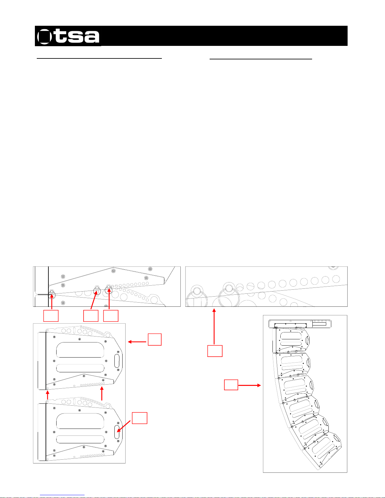
Modo de ensamble y reglaje de las unidades.
Instrucciones de montaje:
1.Se ubica la caja de arriba, insertando la bielas de la caja de
abajo, dentro de las hendiduras de la caja de arriba, (Ver
detalle 1).
2. Una vez acopladas las dos cajas correctamente, se
procede a insertar los dos pasadores de 8 mm. en los taladros
delanteros del aparejo, que ejercen la función de bisagra, (Ver
detalle 2).
3. A continuación se insertan otros dos pasadores en los
taladros de las correderas traseras del aparejo, para facilitar el
trabajo al operario, (Ver detalle 3).
4. Una vez comprobado que las cajas están perfectamente
conectadas (Con los 2 pasadores por lado), observaremos
que la unión entre las cajas, puede variar (De 0º a 10º)
verticalmente. Entonces insertamos otros dos pasadores, para
fijar el ángulo vertical deseado entre las dos cajas, (Ver
detalle 4).
5. Para modificar el ángulo entre unidades, procederemos a
cambiar de posición los pasadores del detalle 4, ayudados por
el agarre del asa trasera, (Ver detalle 5). Esta operación no
ofrece ningún peligro, siempre que los pasadores 2 y 3 estén
conectados.
6. El aparejo, permite variar el ángulo vertical (Entre las
unidades) de 0 a 10 grados, (Ver detalle 6).
7. Una vez finalizadas estas operaciones, el cluster quedará
perfectamente ensamblado, (Ver detalle 7).
Rigging and adjustment of the units.
Rigging instructions:
1. To join the units, insert the rods of the unit below
into the recesses of the unit above (see detail 1).
2. Once the two units have been correctly joined,
insert the two 8mm pins in the front holes of the rig,
which act as a hinge, (see detail 2).
3. Next, insert another two pins into the holes of the
rear sliders of the rig which will facilitate the
mounting procedure (see detail 3).
4. After checking that the units are correctly joined
together (with 2 pins per side), you will see that the
union between the units can be varied vertically
(from 0º to 10º). Insert another two pins to set the
desired vertical angle between the two units, (see
detail 4).
5. To change the angle between units, change the
position of the pins (detail 4) making use of the rear
handle to do so, (see detail 5). This operation is not
dangerous as long as pins 2 and 3 are connected.
6. The adjustment mechanism, allows the vertical
angle (between units) to be varied from 0 to 10
degrees, (see detail 6).
7. Once these operations are completed, the cluster
will be correctly assembled, (see detail 7).
0
º
,
0
.
2
5
º
,
1
º
,
2
º
,
3
º
,
4
º
,
5
º
,
6
º
,
7
º
,
8
º
,
9
º
,
1
0
º
0
º
,
0
.
2
5
º
,
1
º
,
2
º
,
3
º
,
4
º
,
5
º
,
6
º
,
7
º
,
8
º
,
9
º
,
1
0
º
1
2 3 4
5
7
6
Page 7
7
MANUAL DEL USUARIO / USER’S MANUAL
HARD series: AX-212TR
TSA. Subject to change without notice.
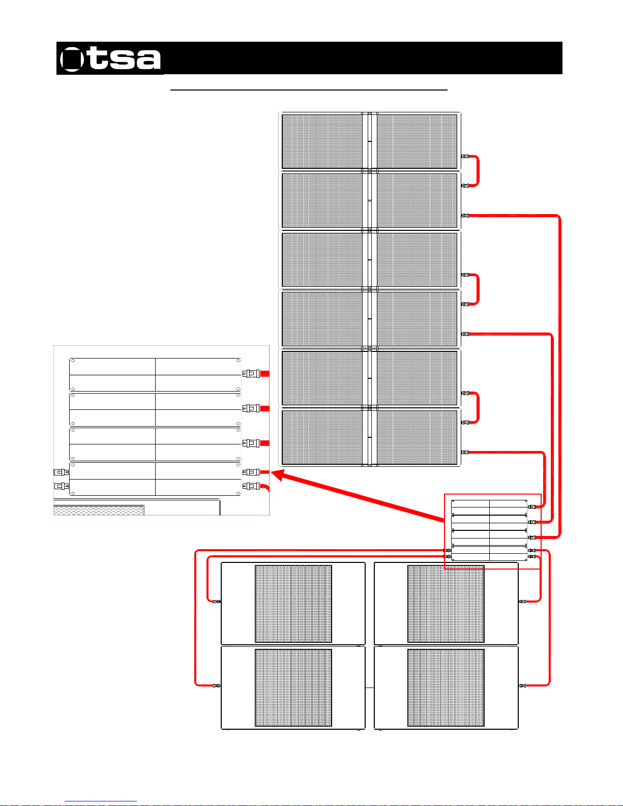
Configuración / Configuration (6 x AX-212TR + 4 x SB-218LX)
1500 W. / 4 oh
1500 W. / 4 oh
1500 W. / 4 oh
1500 W. / 4 oh
3000 W. / 4 oh
3000 W. / 4 oh
3000 W. / 4 oh
3000 W. / 4 oh
1500 W. / 4 oh
1500 W. / 4 oh
1500 W. / 4 oh
1500 W. / 4 oh
1500 W. / 4 oh
1500 W. / 4 oh
1500 W. / 4 oh
1500 W. / 4 oh
1500 W. / 4 oh
1500 W. / 4 oh
1500 W. / 4 oh
1500 W. / 4 oh
3000 W. / 4 oh
3000 W. / 4 oh
3000 W. / 4 oh
3000 W. / 4 oh
1500 W. / 4 oh
1500 W. / 4 oh
1500 W. / 4 oh
1500 W. / 4 oh
1500 W. / 4 oh
1500 W. / 4 oh
1500 W. / 4 oh
1500 W. / 4 oh
Page 8
8
MANUAL DEL USUARIO / USER’S MANUAL
HARD series: AX-212TR
TSA. Subject to change without notice.
Ubicación
Coloque los altavoces por delante de los micrófonos, si los
utiliza. La realimentación (feedback) o acople ocurre cuando
los micrófonos recogen el sonido que sale de los altavoces y
los introducen de nuevo en el sistema.
La realimentación puede provocar graves daños en su caja.
Si el espacio es limitado, dirija los altavoces hacia donde no
estén los micrófonos, para reducir el acople.
Si usa platos giradiscos, coloque los altavoces lejos de los
platos giradiscos. Si la aguja del plato giradiscos recoge la
señal de los altavoces y la re-amplifica se produce un acople
de las bajas frecuencias. Se recomienda el uso de una base
sólida en el plato giradiscos.
Seguridad
Es importante que los altavoces se utilicen de forma segura.
Los altavoces de estos modelos son capaces de generar
niveles extremadamente altos de sonido y se deberán utilizar
con precaución.
La pérdida auditiva en las personas es acumulativa y puede
originarse en aquellas personas que están expuestas
durante largos períodos a niveles superiores a los 90dB.
Nunca permanezca en las proximidades de altavoces que
generan sonidos a elevados niveles.
Montaje en columna
Asegúrese de que el piso o el escenario son sólidos y están
convenientemente nivelados.
No construya pilas demasiado altas de altavoces en
aplicaciones al aire libre dónde el viento pueda moverlas.
Tenga en cuenta que los altavoces que rinden niveles de
muy alta potencia de sonido pueden moverse o vibrar y
desplazarse.
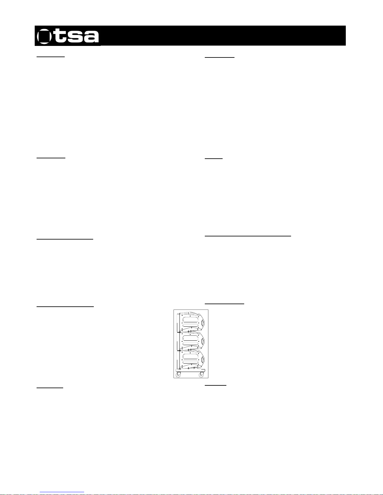
Sistema de voladura
Las cajas AX-212RT están dotadas de un sistema
de voladura, tal como se indica en la página nº 4 de
este manual. Este sistema solo permite volar un
máximo de 16 cajas suspendidas una debajo de
otras, utilizando los pasadores de anclaje como
indica este dibujo. Como se puede observar, la
pieza superior de volado, esta diseñada para: Volar
el grupo de unidades suspendido mediante unas
eslingas, como indica el dibujo
Cableado
Al conectar un sistema de altavoces a un amplificador se
recomienda que la resistencia de retorno del cable utilizado
sea menor de una décima parte de la impedancia nominal
del sistema o de los sistemas conectados en paralelo.
Si los cables de conexión tienen poca sección, o son
demasiado largos, aumentará la impedancia del sistema y
obtendremos una caída de tensión, que disminuirá la
potencia que pueda llegar a los altavoces.
Placement
If you are using microphones, place the loudspeakers
in front of them. Feedback occurs when the
microphones pick up the sound coming from the
loudspeakers and send it through the system again.
Feedback can seriously damage your unit. If you only
have limited space, point the loudspeakers to an area
where there are no microphones to reduce feedback.
If you use turntables, place the loudspeakers far away
from the turntables. If the turntable's needle picks up
the signal from the loudspeakers, it re-amplifies it and
low frequency feedback occurs. We recommend that
the turntable has a solid base.
Safety
It is important that the loudspeakers are used safely.
These models of loudspeakers are capable of
producing extremely high sound levels and should be
used with caution.
Hearing loss is cumulative and it can affect people
who are exposed to sound levels higher than 90dB for
long periods of time. Never remain in the vicinity of
loudspeakers that are emitting high levels of sound.
Mounting speakers in columns
Make sure that the floor or stage is strong and has a
level surface.
Do not stack up too many speakers in outdoor
applications where the wind could move them. Please
note that loudspeakers operating at very high sound
levels can move or vibrate and shift from their original
position.
Flying system
The AX-212TR speakers are equipped with flying
system hardware as indicated on page 4 of this
manual. Using this system a maximum of 16 units
can be flown, one below another, using the anchor
pins as shown in this drawing. As can be seen, the
top flying system hardware is designed to: Fly the
suspended group of units with slings, as shown in
the drawing.
Cabling
When connecting a loudspeaker system to an
amplifier it is recommended that the return resistance
of the cable used is less than one tenth of the nominal
impedance of the system or systems connected in
parallel. If the connection cables have a small crosssection, or are too long, the system impedance will be
increased and therefore a voltage drop will be
produced, thus reducing the power reaching the
loudspeakers.
 Loading...