

Page 1

1
MANUAL DEL USUARIO / USER’S MANUAL
HARD series: AX-212-3V
TSA. Subject to change without notice.
Manufactured by TSA. / Polígono Alcodar / Carrer Dels musics nº 3 / 46701 Gandia– Valencia (Spain)
Tl: (34) 96 286 8985 / http://www.tsa-sound.com / E.mail: [email protected]
Page 2
2
MANUAL DEL USUARIO / USER’S MANUAL
HARD series: AX-212-3V
TSA. Subject to change without notice.
Introducción
El AX-212/3V, es un sistema Line Array de curvatura variable, la
altura de cada unidad es de 12 pulgadas, se alimenta con
amplificación de 2 vías externa, (la vía de agudos es pasiva).
Monta dos altavoces de 12 pulgadas para la vía de graves, dos
altavoces de 6,5 pulgadas para la vía de medios y tres motores
de 1 pulgada, para la vía de agudos.
Suele combinarse apoyado con los refuerzos de subgraves: SB-
218.
La apertura vertical máxima entre unidades es de 10º. Para
facilitar su montaje incorpora un doble mecanismo de anclaje
que utiliza: Una fijación variable que oscila de entre 0º y 10º a
modo de corredera y otra de posicionamiento fijo para
determinar el ángulo entre unidades. El Sistema de volado
monta el mismo mecanismo de regulación que las propias
unidades.
Precauciones de Seguridad
El signo de exclamación dentro de un triángulo indica
la existencia de componentes internos cuyo reemplazo
puede afectar a la seguridad. Las especificaciones se
encuentran en la etiqueta de la parte posterior del
producto.
Este símbolo indica que el presente producto no puede
ser tratado como residuo doméstico normal, sino que
debe entregarse en el correspondiente punto de
recogida de equipos eléctricos y electrónicos.
El doble recuadro indica que es un equipo Clase II.
No exponga este equipo a lluvia o humedad.
No emplace altavoces en proximidad a equipos
sensibles a campos magnéticos, tales como monitores
de televisión o material magnético de almacenamiento
de datos.
Garantía
Todos nuestros productos están garantizados por un periodo de
24 meses desde la fecha de compra. Las garantías sólo serán
válidas si son por un defecto de fabricación y en ningún caso por
un uso incorrecto del producto. La reparación en garantía cubre
la reposición de las partes defectuosas. Otros cargos como
portes y seguros, son a cargo del comprador en todos los casos.
Para solicitar reparación en garantía es imprescindible que el
producto no haya sido previamente manipulado e incluir una
fotocopia de la factura de compra.
Conexiones
Estos modelos utilizan dos conectores Neutrik Speakon NL4,
específicos para altavoces y permiten una conexión profesional.
Para enchufar un cable a una caja, inserte el conector macho en
cualquiera de las entradas de la caja y gire el
conector macho hacia la derecha, momento
en el que quedará bloqueado. Los dos
conectores están en paralelo (todos los
pines), de forma que cualquiera de ellos
puede usarse indistintamente como entrada
o salida.
Introduction
The AX-212/3V, is a Line Array of variable directivity ,
the height of each unit is 12 inch, is a 3 -way system, is
powered by two amplifier channels (HF passive
crossover network) and houses two 12 inch low
frequency drivers , two 6.5 inch mid frequency drivers
and three 1 inch high frequency compression drivers.
The SB-218 subwoofer is used to reinforce the low
frequencies.
The vertical splay angles between units is 10º. It has an
integrated double rigging mechanism for easy and quick
deployment, a mobile element that allows splay angles
of 0º to 10º, and other fixed element to configure the
splay angles between units. The rigging hardware
features the same rigging mechanism.
Safety Precautions
The exclamation point inside an equilateral triangle
indicates the existence of internal components whose
substitution may affect safety. The specifications can be
found on the rear label of the product.
This symbol on the product indicates that this product
should not be treated as household waste.
Instead it shall be handed over to the applicable
collection point for the recycling of electrical and
electronic equipment. The double square indicates
Class II device. Do not expose to rain or moisture.
Do not place loudspeakers in proximity to devices
sensitive to magnetic fields such as television monitors
or data storage magnetic material.
Warranty
All products are warranted against any manufacturing
defect for a period of 2 years from date of purchase.
The warranty ex-cludes damage from incorrect or
misuse use of the product. All warranty repairs must be
exclusively undertaken by the factory or any of its
authorized service centres. To claim a warranty repair,
do not open or intend to repair the product.
Return the damaged unit, at shippers risk and freight
prepaid, to the nearest service centre with a copy of the
purchase invoice.
Connections
The units comprise two Neutrik Speakon model NL4
connectors, designed specifically for loudspeakers, are
used to ensure both professional and safe connection.
To plug a cable into a unit, insert the male plug into any
of the enclosure's sockets and
turn the male plug to the right so
that it is locked. The two
connectors are in parallel (all
pins) so that either one of them
can be used for input or output.
Manufactured by TSA. / Polígono Alcodar / Carrer Dels musics nº 3 / 46701 Gandia– Valencia (Spain)
Tl: (34) 96 286 8985 / http://www.tsa-sound.com / E.mail: [email protected]
Page 3
3
MANUAL DEL USUARIO / USER’S MANUAL
HARD series: AX-212-3V
TSA. Subject to change without notice.
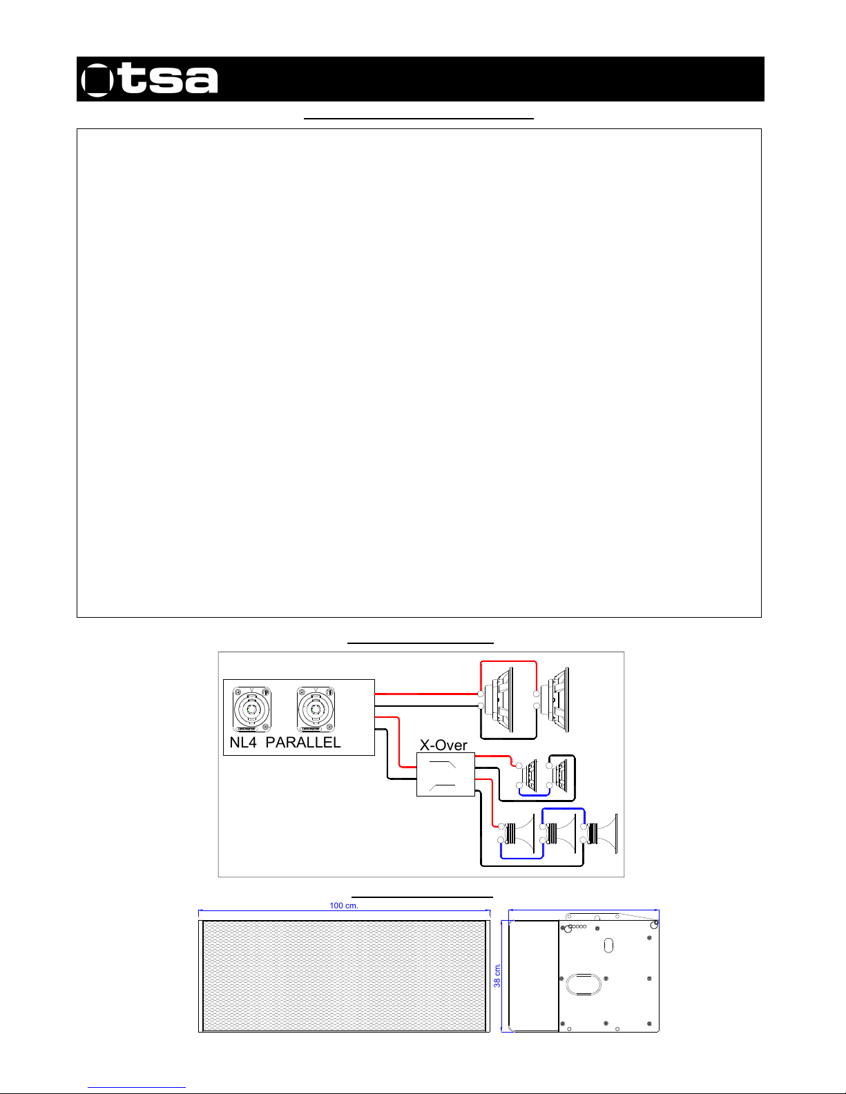
Ficha Técnica / Data sheet AX-212-3V
Connections AX-212-3V
System Description: 3 Way system variable curvature
Frequency Response (+3dB -10dB ). From 50 to 20,000Hz.
Horizontal Coverage (-6dB). 100º
Vertical Coverage (-6dB). Depends on configuration
LF / 4 oh
Feature: 2 x 12" loudspeakers (Ferrite)
Frequency range. From 50 to 300Hz.
Axial Sensitivity (dB SPL, 1 Watt @ 1m) 103 dB.
Power Handling (Watts AES) 1.400
Power Handling (Watts Continuous) 2.800
MAX SPL continuous. 137,5 dB.
MAX SPL (peak). 143,5 dB.
MF / 16 oh
Feature: 2 x 6,5" loudspeakers (Ferrite)
Frequency range. From 300 - 2.000Hz.
Axial Sensitivity (dB SPL, 1 Watt @ 1m) 106 dB.
Power Handling (Watts AES) 500
Power Handling (Watts Continuous) 1.000
MAX SPL continuous. 136,0 dB.
MAX SPL (peak). 142,0 dB.
HF / 24 oh (Passive crossover)
Feature: 3 x 1" Drivers (Ferrite)
Frequency range. From 2.000 - 20.000Hz.
Axial Sensitivity (dB SPL, 1 Watt @ 1m) 112 dB.
Power Handling (Watts AES) 210
Power Handling (Watts Continuous) 420
MAX SPL continuous. 138,2 dB.
MAX SPL (peak). 144,2 dB.
Enclosure
Rigging Hardware. Integrated
Vertical angles range between units
Dimensions. W: 100 cm. H: 38,5 cm. D: 52 cm.
G. Weight 78 kg.
Front Protection Steel coated grill with special foam filter
Constructed: Built in Finland Birch plywood
Finish: Black fine textured Warnex
0º / 1,25º / 2,5º / 5º / 10º (Exponential)
Dimensions AX-212-3V
+
-
+
-
NL4 PARALLEL
Pin +1
Pin - 1
Pin +2
Pin - 2
X-Ove
r
HF
LF
IN
+
-
+
-
+
-
+
-
+
-
100 cm.
3
8
c
m
.
52 cm.
Page 4
4
MANUAL DEL USUARIO / USER’S MANUAL
HARD series: AX-212-3V
TSA. Subject to change without notice.
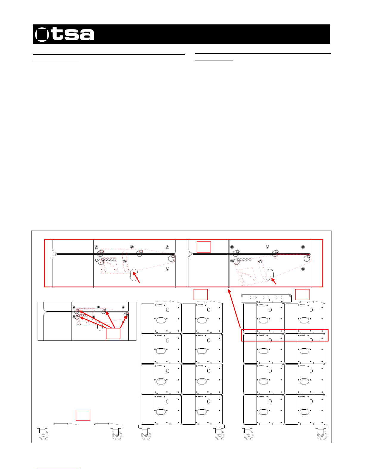
Montaje de dos clusters de cuatro unidades, sobre la
base con ruedas.
El recinto acústico del modelo AX-212-3V, tiene una
estructura rectangular. Para variar el ángulo entre unidades,
se realiza mediante la abertura frontal de las mismas, este
hecho facilita el montaje del cluster.
El aparejo de volado (CHSE212) y la base con ruedas
(CHTS212-3V), utilizan el mismo mecanismo anclaje que las
propias unidades (AX-212-3V).
Instrucciones de montaje:
1. Se deposita la base con ruedas (CHTS212-3V) en un
suelo firme y completamente llano, (Ver figura 1).
2. Se procede a apilar sobre la base con ruedas, las ocho
unidades (AX-212-3V), en dos grupos de cuatro, (Ver figura
2).
3. Se monta el aparejo de volado sobre una de las cajas
superiores, (Ver figura 3).
4. Una vez apiladas las cajas con el aparejo de volado, se
procede ensamblarlas entre si, mediante los pasadores de
10 mm, (Ver figura 4).
5. El aparejo de reglaje de las unidades (AX-212-3V), es
retráctil, al desconectar la biela de la caja superior (Mediante
la extracción de los dos pasadores), se repliega
automáticamente dentro del propio aparejo, (Ver figura 5).
Rigging of two clusters of four units, on the
wheeled base.
The AX-212-3V cabinet has a rectangular structure.
Varying the angle between units is carried out by
opening the angle of the units at the front. This
operation makes for an easy rigging of the cluster
The flying system hardware (CHSE212) and the
wheeled base (CHTS212-3V) use the same
adjustment mechanism as the units themselves (AX212-3V).
Rigging instructions:
1. Place the wheeled base (CHTS212-3V) on a firm
and completely level surface (See Figure 1).
2. Stack the eight units (AX-212-3V) onto the wheeled
base, in two groups of four, (See Figure 2).
3. Mount the flying system hardware on one of the top
units (see Figure 3).
4. Once the units are stacked and the flying system
hardware is fitted, join them together using the 10 mm
pins (See Figure 4).
5. The adjustment hardware of the units (AX-212-3V)
is retractable. Once the rod is disconnected from the
top unit (by removing the two pins), it automatically
retracts into the mechanism itself. (See Figure 5 ).
1
2 3
4
5
Page 5
5
MANUAL DEL USUARIO / USER’S MANUAL
HARD series: AX-212-3V
TSA. Subject to change without notice.
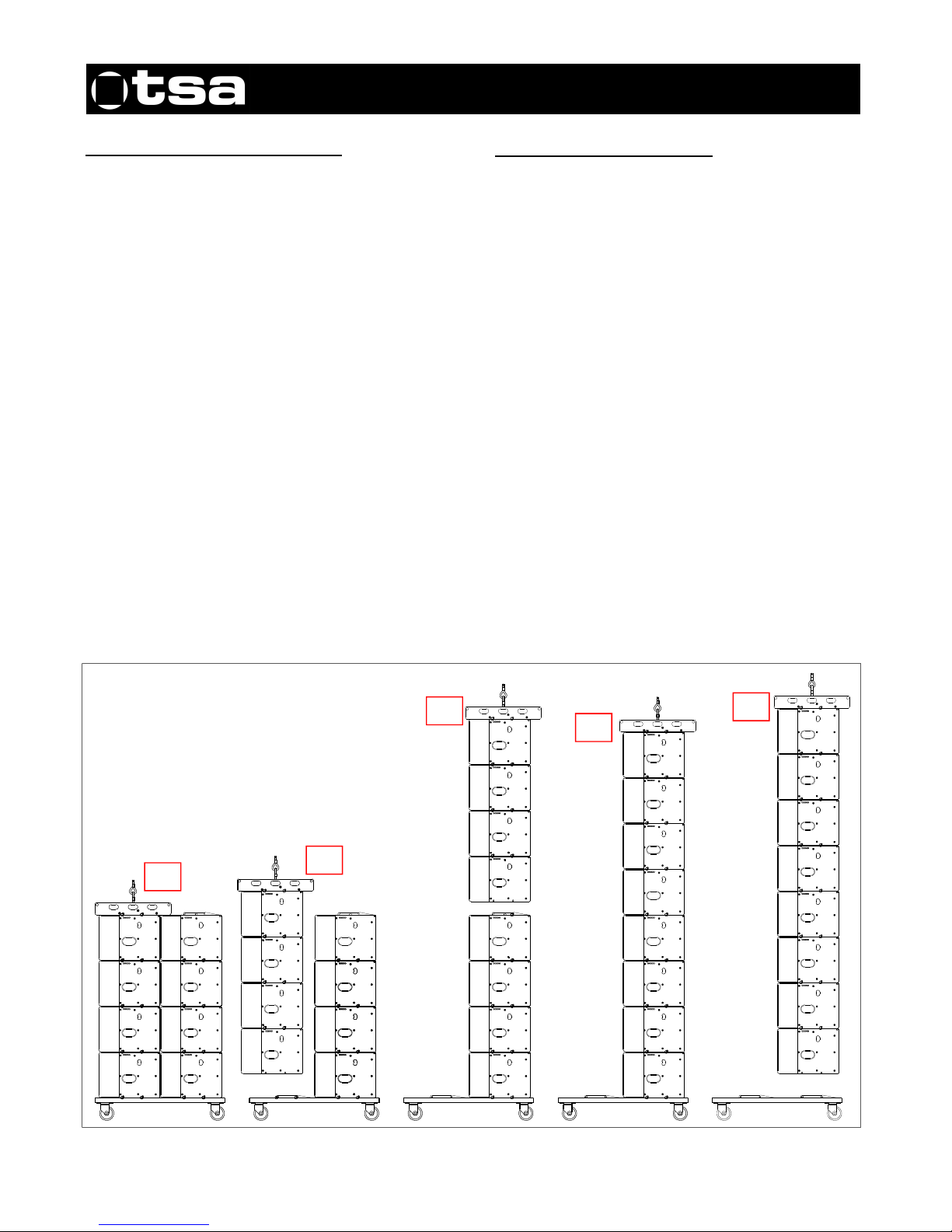
Ensamblado y volado de los clusters.
Instrucciones de montaje:
1. Se sitúa el primer cluster de cuatro unidades con el
aparejo de volado en el punto exacto para ser izado por el
mecanismo de elevación, después, conecta el enganche
del polipasto al orificio correcto del aparejo, (Ver figura 1)
2. Se eleva el primer cluster, previamente desconectado de
la base con ruedas, (Ver figura 2)
3. Una vez elevado el primer cluster, se ubica el segundo
cluster (Sin el aparejo de volado) debajo del primero para
proceder al ensamble de ambos. (Ver figura 3)
4. Se conecta el primer cluster con el segundo, utilizando
los cuatro pasadores de acero de 10 mm de diámetro. (Ver
figura 4)
5. Paso siguiente: Se desconecta el segundo cluster de la
base con ruedas procede al volado de ambos, (Ver figura 5)
Este procedimiento se puede repetir, para el ensamble de
un tercer cluster.
Rigging and flying the clusters.
Rigging instructions:
1. Place the first cluster of four units with its flying
hardware at the exact position, ready to be lifted by the
hoist. Attach the hoist coupling to the lifting ring
inserted at the correct point. (See Figure 1)
2. Raise the first cluster (with the wheeled base
removed). (See Figure 2)
3. With the first cluster raised, position the second
cluster (without the flying system hardware) below the
first cluster and then join both of them together. (See
Figure 3)
4. Join the first cluster to the second using the four
stainless steel 10 mm diameter pins. (See Figure 4)
5. Next step: Remove the second cluster from the
wheeled base. You can now go ahead and fly both of
the clusters (See figure 5)
This procedure can be repeated if you wish to mount a
further third cluster.
1
2
3
4
5
Page 6
6
MANUAL DEL USUARIO / USER’S MANUAL
HARD series: AX-212-3V
TSA. Subject to change without notice.
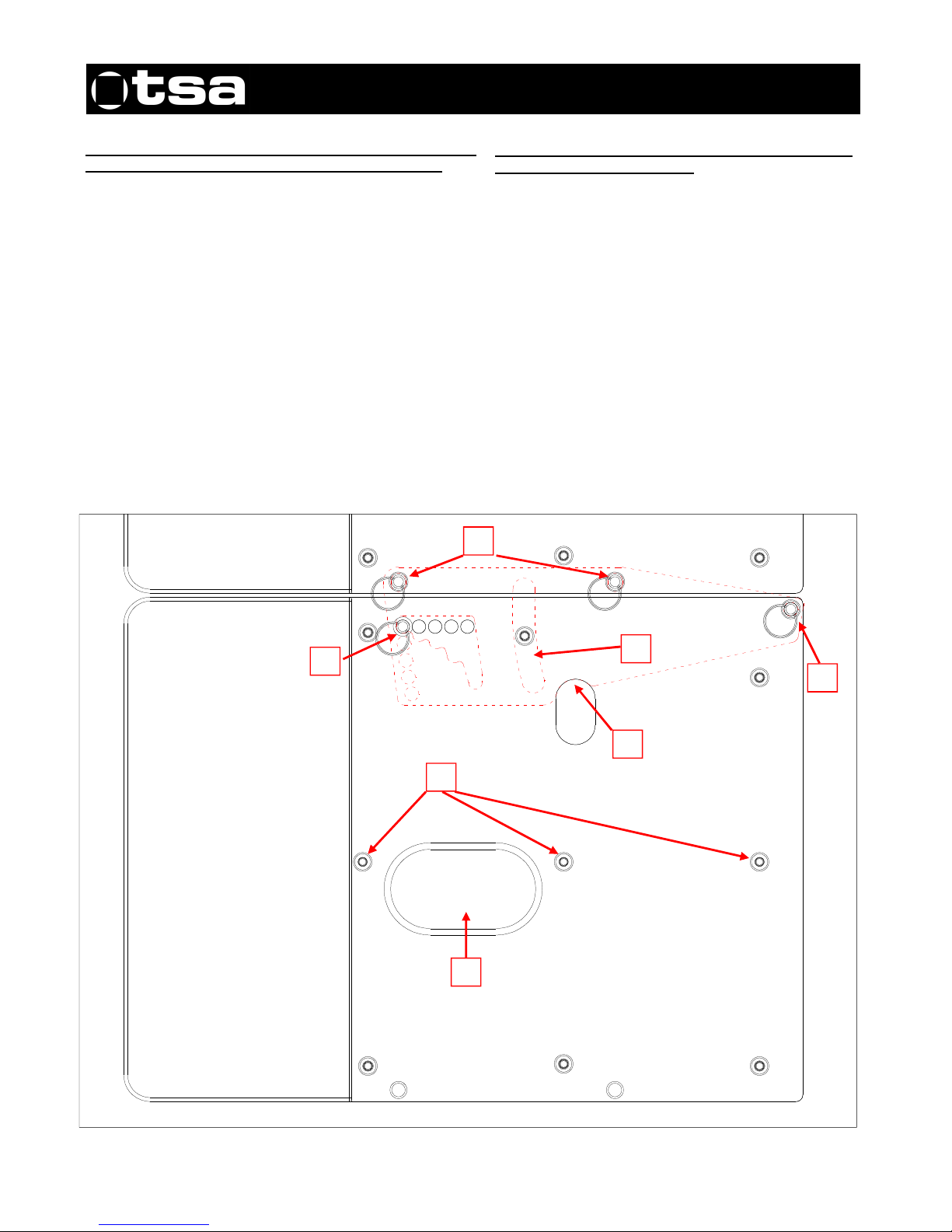
Descripción del aparejo que determina el
posicionamiento del ángulo vertical entre unidades.
1. Corredera de seguridad que permite variar (Entre 0º y
10º) el ángulo vertical entre las cajas. Esta corredera,
mantiene las cajas siempre unidas, aunque se extraiga el
pasador nº 3, encargado de fijar el ángulo.
2. Pasadores de seguridad que se utilizan para conectar la
caja inferior, con la superior.
3. Pasador encargado de fijar el ángulo vertical entre las
unidades apiladas.
4. Orificio de acceso, para la manipulación la biela ubicada
en el interior del aparejo.
5. Tornillos de sujeción del aparejo.
6. Pasador que ejerce la función de bisagra de la propia
biela.
7. Asa de sujeción.
Description of the mechanism that determines the
vertical angle between units.
1. The safety slider that allows a 0º to 10º vertical
angle to be set between units, always keeping them
together, even if pin 3, that adjusts the vertical angle, is
removed.
2. The safety pins that are used to connect the lower
unit with the upper unit.
3. The pin in charge of setting the vertical angle
between the stacked units.
4. The access hole so the rod located inside the rig
can be reached.
5. Fixing screws of the unit.
6. Pin that acts as a hinge.
7. Handle.
1
2
3
4
5
6
7
Page 7
7
MANUAL DEL USUARIO / USER’S MANUAL
HARD series: AX-212-3V
TSA. Subject to change without notice.
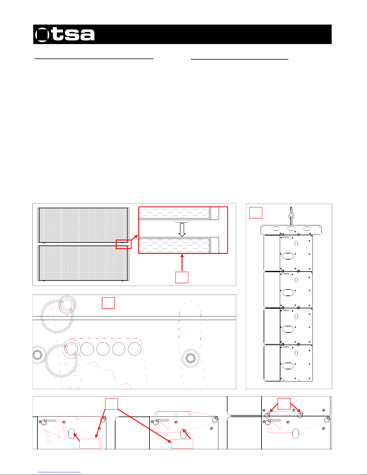
Modo de ensamble y reglaje de las unidades.
Instrucciones de montaje:
1.Se apilan las cajas en vertical, comprobando que los
patines la caja superior, encajen perfectamente con las
alojamientos de la caja inferior, (Ver detalle 1).
2. Una vez acopladas las dos cajas correctamente, se
extrae la biela de la caja inferior, empujándola hacia arriba.
(Esta manipulación, se ejecuta a través del orificio de la
cubierta del aparejo, Ver detalle 2).
3. A continuación se procede a conectar la biela de la caja
inferior, insertando los pasadores en los orificios de la caja
superior, (Ver detalle 3).
4. Una vez comprobado que las cajas están perfectamente
conectadas (Con los 2 pasadores por lado), observaremos
que la unión entre las cajas, puede variar (De 0º a 10º)
verticalmente. (Ver detalle 4). Para modificar el ángulo entre
unidades, procederemos a cambiar la posición los
pasadores en los distintos orificios.
5. Una vez finalizadas estas operaciones, el cluster quedará
perfectamente ensamblado, (Ver detalle 5).
Rigging and adjustment of the units.
Rigging instructions:
1. Stack the units vertically making sure that the skids
of the top unit, fit exactly with the slots of the lower unit
(see Detail 1).
2. Once the two units have been correctly joined,
remove the rod from the lower unit by pushing it
upwards. (This is done by locating the rod via the
access hole in the unit; see Detail 2).
3. Next, connect the rod of the lower unit by inserting
the pins into the holes of the upper unit (see Detail 3).
4. After checking that the units are correctly joined
together (with 2 pins per side), you will see that the
union between the units can be varied vertically (from
0º to 10º). (see detail 4). Change the position of the
pins to set the desired vertical angle between the two
units,
5. Once these operations are completed, the cluster
will be correctly assembled, (see Detail 5).
1
0º 1,25º 2,5º 5º 10º
4
2
3
Step 1
Step 2
5
Page 8
8
MANUAL DEL USUARIO / USER’S MANUAL
HARD series: AX-212-3V
TSA. Subject to change without notice.
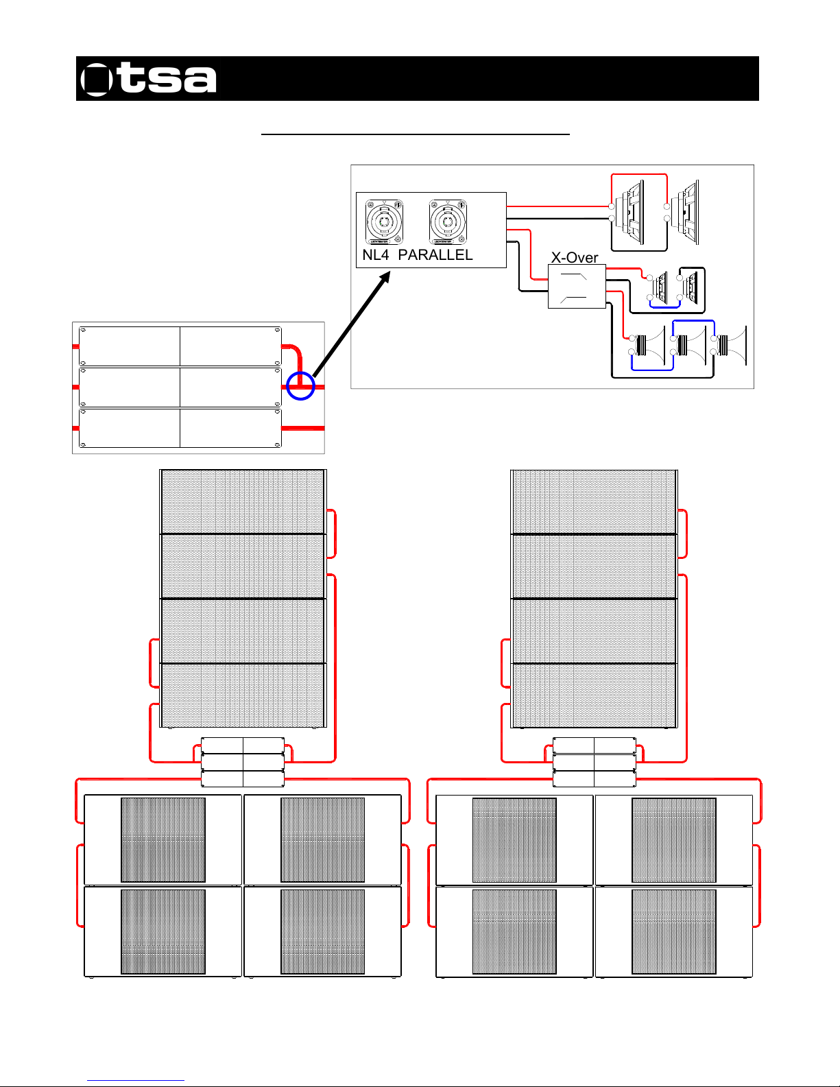
Configuración / Configuration AX-212-3V + SB-218
LF
3000W. / 2 oh.
6000W. / 2 oh.6000W. / 2 oh.
HF
3000W. / 2 oh.
LF
3000W. / 2 oh.
HF
3000W. / 2 oh.
LF
3000W. / 2 oh.
6000W. / 2 oh.6000W. / 2 oh.
HF
3000W. / 2 oh.
LF
3000W. / 2 oh.
HF
3000W. / 2 oh.
LF
3000W. / 2 oh.
6000W. / 2 oh.6000W. / 2 oh.
HF
3000W. / 2 oh.
LF
3000W. / 2 oh.
HF
3000W. / 2 oh.
+
-
+
-
NL4 PARALLEL
Pin +1
Pin - 1
Pin +2
Pin - 2
X-Ove
r
HF
LF
IN
+
-
+
-
+
-
+
-
+
-
Page 9
9
MANUAL DEL USUARIO / USER’S MANUAL
HARD series: AX-212-3V
TSA. Subject to change without notice.
Ubicación
Coloque los altavoces por delante de los micrófonos, si los
utiliza. La realimentación (feedback) o acople ocurre cuando
los micrófonos recogen el sonido que sale de los altavoces y
los introducen de nuevo en el sistema.
La realimentación puede provocar graves daños en su caja.
Si el espacio es limitado, dirija los altavoces hacia donde no
estén los micrófonos, para reducir el acople.
Si usa platos giradiscos, coloque los altavoces lejos de los
platos giradiscos. Si la aguja del plato giradiscos recoge la
señal de los altavoces y la re-amplifica se produce un acople
de las bajas frecuencias. Se recomienda el uso de una base
sólida en el plato giradiscos.
Seguridad
Es importante que los altavoces se utilicen de forma segura.
Los altavoces de estos modelos son capaces de generar
niveles extremadamente altos de sonido y se deberán utilizar
con precaución.
La pérdida auditiva en las personas es acumulativa y puede
originarse en aquellas personas que están expuestas
durante largos períodos a niveles superiores a los 90dB.
Nunca permanezca en las proximidades de altavoces que
generan sonidos a elevados niveles.
Montaje en columna
Asegúrese de que el piso o el escenario son sólidos y están
convenientemente nivelados.
No construya pilas demasiado altas de altavoces en
aplicaciones al aire libre dónde el viento pueda moverlas.
Tenga en cuenta que los altavoces que rinden niveles de
muy alta potencia de sonido pueden moverse o vibrar y
desplazarse.
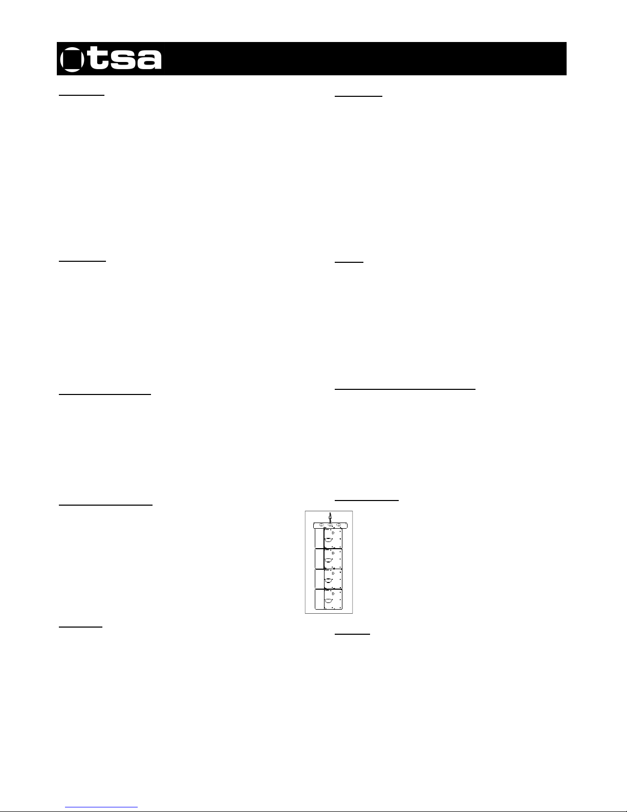
Sistema de voladura
Las cajas AX-212-3V están dotadas de un sistema de
voladura, tal como se indica en la página nº 4 de este
manual. Este sistema solo permite volar un máximo de
12 cajas suspendidas una debajo de otras, utilizando los
pasadores de anclaje. Como se puede observar, la
pieza superior de volado, esta diseñada para: Volar el
grupo de unidades suspendido mediante unas eslingas,
como indica el dibujo
Cableado
Al conectar un sistema de altavoces a un amplificador se
recomienda que la resistencia de retorno del cable utilizado
sea menor de una décima parte de la impedancia nominal
del sistema o de los sistemas conectados en paralelo.
Si los cables de conexión tienen poca sección, o son
demasiado largos, aumentará la impedancia del sistema y
obtendremos una caída de tensión, que disminuirá la
potencia que pueda llegar a los altavoces.
Placement
If you are using microphones, place the loudspeakers
in front of them. Feedback occurs when the
microphones pick up the sound coming from the
loudspeakers and send it through the system again.
Feedback can seriously damage your unit. If you only
have limited space, point the loudspeakers to an area
where there are no microphones to reduce feedback.
If you use turntables, place the loudspeakers far away
from the turntables. If the turntable's needle picks up
the signal from the loudspeakers, it re-amplifies it and
low frequency feedback occurs. We recommend that
the turntable has a solid base.
Safety
It is important that the loudspeakers are used safely.
These models of loudspeakers are capable of
producing extremely high sound levels and should be
used with caution.
Hearing loss is cumulative and it can affect people
who are exposed to sound levels higher than 90dB for
long periods of time. Never remain in the vicinity of
loudspeakers that are emitting high levels of sound.
Mounting speakers in columns
Make sure that the floor or stage is strong and has a
level surface.
Do not stack up too many speakers in outdoor
applications where the wind could move them. Please
note that loudspeakers operating at very high sound
levels can move or vibrate and shift from their original
position.
Flying system
The AX-212-3V speakers are equipped with
flying system hardware as indicated on page 4 of
this manual. Using this system a maximum of 16
units can be flown, one below another, using the
anchor pins. As can be seen, the top flying
system hardware is designed to: Fly the
suspended group of units with slings, as shown
in the drawing.
Cabling
When connecting a loudspeaker system to an
amplifier it is recommended that the return resistance
of the cable used is less than one tenth of the nominal
impedance of the system or systems connected in
parallel. If the connection cables have a small crosssection, or are too long, the system impedance will be
increased and therefore a voltage drop will be
produced, thus reducing the power reaching the
loudspeakers.
 Loading...