

Page 1
T roubleshooting Guide
DEAD SET
(NO RASTER/NO SOUND)
112V(or 118V)
Check the heater elements of
CPT are lighting or not
No
Check/Replace FR423
Yes
Check the voltage at
C430(+)
0.1V
Check/Replace IC430
R430, IC401, D411, FR422
0.1V
Check/Replace IC501
Check +B voltage at J131
8V
Check the voltage
at pin21 of IC501
over 0.4V
Check/Replace IC01
(IC202, IC01T, IC02T:
in case of with TXT)
Lower than 6V
0V
Check the rectified voltage of
main power at C817(+)
0V
Check/Replace
F801, DB813, R821, T801
~380V
150
Check the voltage
at pin9 of IC802
Check/Replace
D810, ZD810, Q810
6~8V
Check/Replace
IC802, D806, D811.
Check the secondary
voltage are short
Page 2
NO PICTURE/NO SOUND
Check the voltage of
TUNER MB(12V)
Check/Replace
Tuner
Check the tuning
condition
Check the 33V at C416(+)
Check/Replace
R421, ZD404
Check/Replace
FR422, D411, IC401
(RASTER OK)
11.8~ 12.2V
0V
Page 3
NO RASTER(SOUND OK)
Check heater elements of
CRT are lighting
Check the AC voltage at H/T
pin of CPT SOCKET
on CPT board
Check/Replace
CPT
Check/Replace
FR423, 420
The screen is
blinking
Check replace
IC501
Readjust White
Balance
Check the 180V
line at C418(+)
Check/Replace
D413
Retrace line
is visible
Check the screen voltage (G2)
alignment is correct or not
Check the screen colour
Check the base voltage
of Q901-Q903
Check/Replace
D901~ D903
Check/Replace
R918-920 or
soldering
condition on
CPT board.
No
Yes
Abnormal
White
Abnormal
R/G/B
Normal
12V
4~ 5V
6.0~ 6.5Vrms
0Vrms
Page 4
NO SOUND(PICTURE OK)
Check the voltage(SMPS 25V)
at pin5 of IC601
Check/Replace of
FR804, D801
Check the soldering
state around IC601
Check/Replace
IC01
Check/Replace IC430
Check/Replace IC501
Check the voltage at pin16
of IC501
Check/Replace Q508
(TV/AV, TXT switch)
Check the voltage
at pin 10 of IC501
Check the voltage
at pin 5 of IC501
Check the voltage at pin 4
of IC630
Check/Replace IC401,
FR422
Check I2C BUS
(SCL,SDA) of IC630
Check/Replace IC630
Check the voltage at pin 8
of IC601
Check/Replace IC01
Check/Replace IC601
Abnormal
Abnormal
Normal(20~ 27V)
10~12V
Normal
7~9V
0V
Page 5
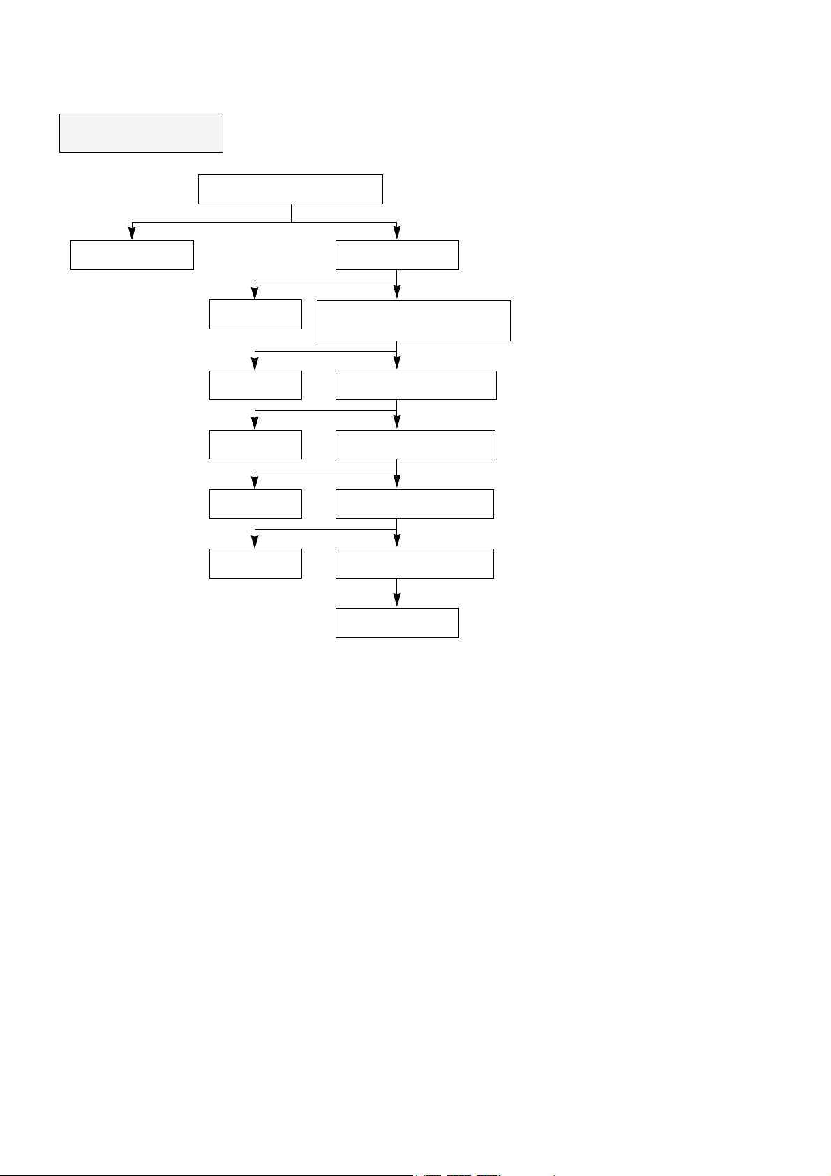
NO COLOR
Check the frequency(4.43/3.58MHz)
at pin 34.35 of IC501
Check/Replace
X501, 502
Check/Replace
IC501
Check/Replace
IC01
Check/Replace
IC501
Check/Replace
IC503
Check/Replace
IC502
Check the voltage
of PIN27 of IC501.
Check whether the voltage is swing
or not at the pin5 of IC01 according to
changing colour up/down
Check whether R-Y and B-Y are out
from pin30 and pin31 of IC501
Check whether R-Y and B-Y are
out from pin9 and pin10 of IC503
Check whether R-Y and B-Y are
out from pin11 and pin12 of IC502
Check wheter R/G/B is out from
pin20, pin19 and pin18 of IC501
Check/Replace
IC501
Abnormal
Abnormal
Swing
Swing
Yes
Yes
No
Below 5V
Not
Not
No
No
Normal
Page 6
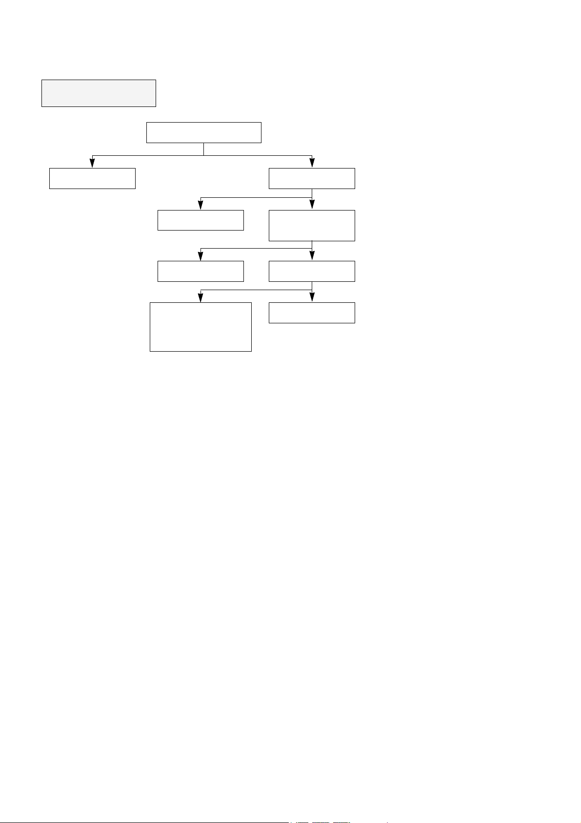
NO TELETEXT
Check the voltage 12V at C403(+)
Check the 12V line
to be correct
Check/Replace
IC02T
Check/Replace
Q01T
- Check/Replace
IC01T, IC02T
µ-COM(IC01)
- Check all the connections of
SDA SCL
Check the voltage of
C13T(+)
Check video signal is
normal at the pin8 of IC01T
Check I2C Bus (SDA, SCL)
Check/Replace X01T
Abnormal
Abnormal
Normal
4.8~ 5.2V
Yes
Yes
NO
NO
 Loading...