

Page 1
Installation and
Maintenance
Limited One Year Warranty
(Commercial Applications)
T&S warrants to the original purchaser (other
than for purposes of resale) that such product is
free from defects in material and workmanship for
a period of one (1) year from the date of purchase.
During this one-year warranty period, if the product
is found to be defective, T&S shall, at its options,
repair and/or replace it. To obtain warranty service,
products must be returned to...
T&S Brass and Bronze Works, Inc.
Attn: Warranty Repair Department
2 Saddleback Cove
Travelers Rest, SC 29690
Shipping, freight, insurance, and other
transportation charges of the product to T&S and
the return of repaired or replaced product to the
purchaser are the responsibility of the purchaser.
Repair and/or replacement shall be made within a
reasonable time after receipt by T&S of the returned
product. This warranty does not cover Items which
have received secondary fi nishing or have been
altered or modifi ed after purchase, or for defects
caused by physical abuse to or misuse of the
product, or shipment of the products.
Any express warranty not provided herein, and
any remedy for Breach of Contract which might
arise, is hereby excluded and disclaimed. Any
implied warranties of merchantability or fi tness
for a particular purpose are limited to one year in
duration. Under no circumstances shall T&S be
liable for loss of use or any special consequential
costs, expenses or damages.
Some states do not allow limitations on how
long and implied warranty lasts or the exclusion or
limitation of incidental or consequential damages,
so the above limitations or exclusions may not apply
to you. Specifi c rights under this warranty and other
rights vary from state to state.
Attention California Residents:
“WARNING: This product contains chemicals
known to the State of California to cause cancer,
and birth defects or other reproductive harm.”
P/N: 098-009518-45 Rev.3
Date: 08-15-16
Drawn: TEH
Checked: JRM 09-29-16
Approved: JHB 10-08-16
Instructions
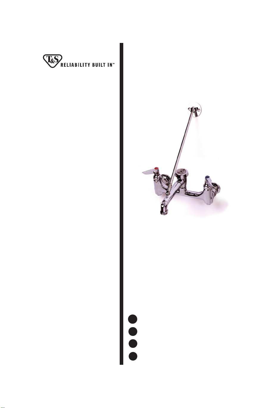
Surgical Sink and
Service Sink Faucets
with Built-In Stops
B-0665-BST Series
Español:
ES
Instrucciones de instalación y mantenimiento
Français:
FR
Instructions pour l’installation et la maintenance
Deutsch:
DE
Installations- und Wartungsanleitungen
中文:
CN
安装与维护说明
Page 2
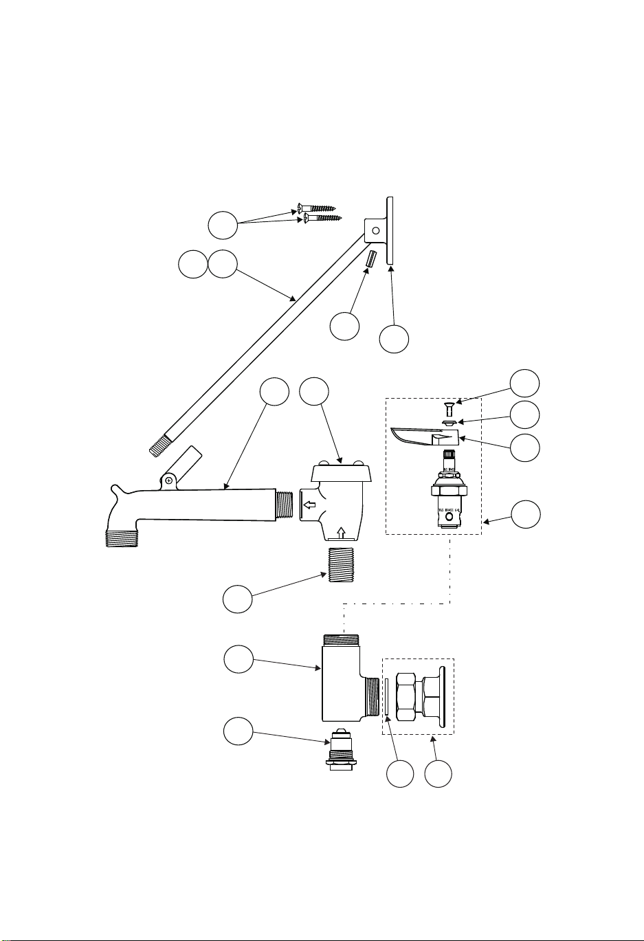
Exploded View
14
1213
15
1011
5
1
16
9
8
7
6
4
2
3
2
Page 3

Part Number Guide
Service Sink Faucet Assemblies
1 Body, Faucet N/A
2 Asm, Flange Coupling 00AA
3 Washer, Coupling Flange 001019-45
4 Asm, BST Spindle & Insert 163A
5 Nipple, Close 1/2 HWL 002534-25
6 Asm, Eterna w/ Spring Checks & Handle (Cold) 002711-40
6 Asm, Eterna w/ Spring Checks & Handle (Hot) 002712-40
7 Handle, Lever (Blank) 001638-45
8 Index, Button (Red / Hot) 001661-45
8 Index, Button (Blue / Cold) 001660-45
9 Screw, Handle 000922-45
10 Asm, Vacuum Breaker, 1/2” B-0969
11 Spout (BSTR) 009545-25
11 Spout (BSTP) 009545-40
12 Asm, Upper Nozzle Support 009546-40
13 Rod, Support 005060-40
14 Screw, Wall Mount (1 each) 000915-45
15 Pin, Coiled 3/16” x 1/2” S.S. 004713-25
16 Flange 003007-40
3
Page 4
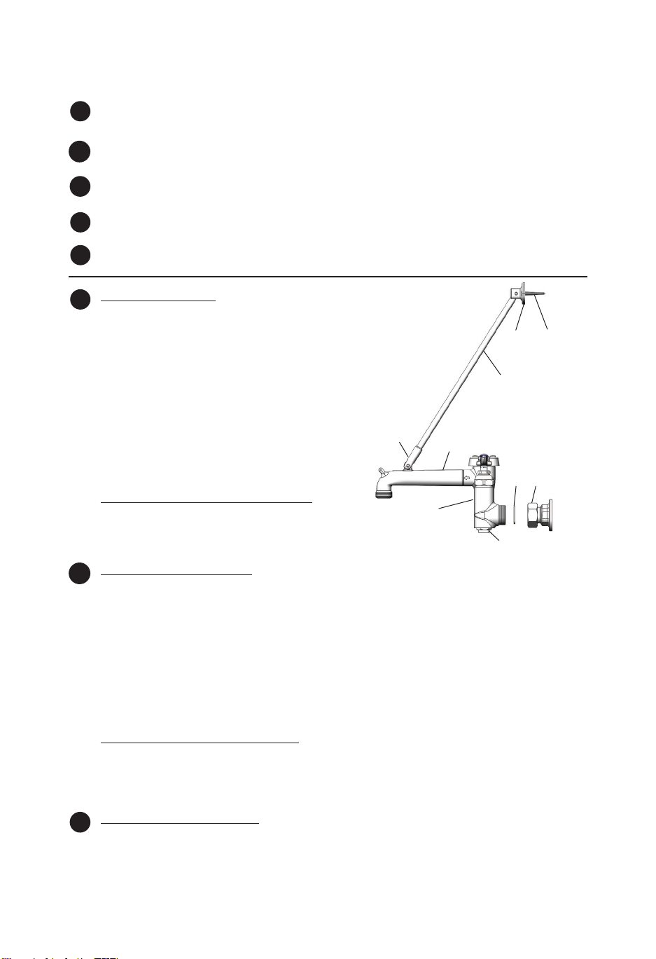
Note: This is a general instructional example of units using -BST.
EN
Nozzles should be installed on unit rst.
Nota: Esto es un ejemplo general instruccional de unidades que utilizan - BST.
ES
(Interceptor Incorporado.) Primero se debe de instalar las boquillas.
Celui-ci être un exemple générale et instructif des élément s qui utiliser BST
FR
Les ajutages devoir être installer au début.
Anmerkung: Die ist ein allgemeines Installationsbeispiel für Armaturen, die BST
DE
verwenden. Düsen sollten zuerst auf die Einheit installiert werden.
注意:这是-BST系列的常规说明样例。首先应将水嘴安装在装置上。
CN
Faucet Installation:
EN
1. Shut o water supply and drain lines. Drill (2) two 7/8”
[2.2 cm] holes in wall or backsplash of sink, 8” [20 cm]
center to center, where you are installing no.1.
2. Apply te on tape or pipe joint compound to threads
of water supply lines.
3. Remove no.2 from no. and attach no.2 to water
supply lines ush against wall. Tighten by hand. Trim
supply lines if necessary.
4. Attach no.1 to no.2, adjusting center to center t by
turning no.2 if needed. Make sure no.3 remains in
place. Tighten no.2 rmly with a wrench.
5. Turn on water supply and check for leaks.
clevis
Abrazadera
clevis
Hebel
连接钩
Upper Nozzle Support Installation:
6. Attach no.13 to no.11 by screwing no.13 into clevis
on no.11.
7. Position no.16 against wall. Mark holes and secure no.16 to wall using no.14.
Instalación De La Canilla:
ES
1. Cierre la fuente de agua y desagüe las tuberias. Perfore (2) dos huecos de 2 cm en la pared o el
espaldar del lavatorio, con 20 cm de centro a centro donde la parte No.1 será instalada.
2. Aplique cinta de Te on o compuesto de coyuntura a las roscas de las lineas de surtido.
3. Remuéva la parte No.2 de la parte No.1 y conecte la parte No.2 a las lineas de surtido pareja con
la pared. Aprete a mano. Si es necesario recorte las lineas de surtido.
4. Conecte la parte No.1 a la parte No.2, ajustando la medida de centro a centro girando la parte
No.2 si es necesario. Asegúrese que la parte No.3 permanezca situada. Con una llave aprete
rmemente la parte No.2.
5. Abra el surtido de agua e inspeccione por ltraciones.
11
1
16
14
13
23
4
Instalación De Soporte Superior:
6. Conecte la parte No.13 a la parte No.11 atornillando la parte No.13 dentro de la abrazandera
en la parte No.11.
7. Coloque la parte No.16 contra la pared. Señale los huecos y asegure la parte No.16 a la pared
usando la parte No.14.
L’Installation du Robinet:
FR
1. Fermer la réserve de l’eau et égoutter la tuyauterie. Percer (2) deux trous de 2.2cm dans le mur
ou le garde-boue de l’ évier 20cm de centre à centre où vous aller installer Nº.1.
4
Page 5

2. Appliquer le ruban en Té on ou le composé pour les tuyaux aux tuyaux qui fournir l’eau.
3. Enlever Nº. 2 de Nº.1 et attacher Nº.2 aux tuyaux qui fournir l’eau au même niveau du mur.
Resserrer par le main. Couper les tuyaux qui fournir l’eau si nécessaire.
4. Attacher Nº.1 à Nº.2, en réglant l’ajustement centre à centre en tournant Nº.2 si nécessaire.
Soyez certain que Nº.3 rester à sa place. Resserer Nº.2 fermement avec une clef anglaise.
5. Recommencer l’eau et véri er s’il y a des fuites.
L’Installation du Support de L’Ajutage en Haut:
6. Attacher Nº.13 à Nº.11 en vissant Nº.13 dans le clevis sur Nº.11.
7. Mettre Nº.16 contre le mur. Marquer les trous et attacher Nº.16 au mur en utilisant Nº.14.
Einbau des Wasserhahns:
DE
1. Den Wasserzulauf schließen und die Leitungen leeren. Zwei 2 cm Löcher in die Wand oder die
Rückwand der Spüle - je nachdem, wo Nr. 1 installiert werden soll - mit einem Mittenabstand von
20 cm bohren.
2. Für die Gewinde der Wasserzuleitungen Te onband oder Rohrdichtungsmasse verwenden.
3. Nr. 2 von Nr. 1 entfernen und Nr. 2 bündig zur Wand auf die Wasserzulau eitungen aufdrehen.
Mit der Hand festziehen. Zulau eitungen bei Bedarf kürzen.
4. Nr. 1 an Nr. 2 befestigen, wobei auf mittigen Sitz zu achten ist und bei Bedarf Nr. 2 gedreht
werden kann. Sicherstellen, daß Nr.3 an Ort und Stelle verbleibt! Nr. 2 mit einem Schrauben
schlüssel festdrehen.
5. Wasserzulauf andrehen und auf Dichtigkeit überprüfen.
Einbau des oberen Schwenkarms:
6. Nr. 13 an Nr. 11 befestigen, indem Nr. 13 an dem Hebel auf Nr. 11 angeschraubt wird.
7. Nr. 16 an der Wand in Position bringen. Löcher markieren und Nr. 16 mit Hilfe von Nr. 14 an der
Wand sichern.
龙头的安装:
CN
1.关闭供水和排水管道。在墙面或者水槽的防溅挡板上面钻(2)两个7/8”[2.2cm]的孔,中心
距为8”[20cm],在孔上安装1号。
2.在供水管道的螺纹上缠上胶带或涂上管道胶合剂。
3.将2号从1号上拆下,把2号平对着墙装在供水管道上,用手拧紧。根据实际情况修整供水管
道。
4.把1号装到2号上,可根据需求旋转2号来调整中心距。请务必确保3号在准确的位置。用扳手
将2号牢牢拧紧。
5.打开供水开关,检查是否漏水。
水嘴上方支架安装:
6.把13号拧到11号上的连接钩上。
7.将16号靠墙放好,并做好记号,用14号把16号固定在墙上。
Adjusting Built-in Stops:
EN
Insert a screwdriver to adjust no.4 at the base of no.1 on each side. Water should be turned on for
this procedure.
Close Stop turn clockwise
Detenedor cerrado gire a la derecha
Fermer l’arrêt tourner dans le sens des
aiguilles d’une montre
Anschlag für Geschlossen:
im Uhrzeigersinn drehen
顺时针方向关闭开关
Open Stop turn counterclockwise
Detenedor Abierto gire a la izquierda
Ouvert l’arrêt tourner dans le sens
inverse des aiguilles d’une montre
Anschlag für O en:
gegen den Uhrzeigersinn drehen
逆时针方向打开开
5
Page 6

Botton view of faucet body and Built-in Stop
Vista posterior de la canilla y Detenedor
no.4 adjusting screw
Parte no.4 tornillo de ajuste
Nº.4 reglant la vis
Justierschraube Nr. 4
4号调节螺丝
Ajuste De Los Detenedores Incorporados:
ES
Para ajustar la parte No.4 insarte un destornillador por debajo de la parte No.1 en ambos lados. El
agua debe estar abierta para este proceso.
La Réglage des Arrêts Encastrés:
FR
Insérer un tournevis pour régler Nº.4 à la base de Nº.1 sur chaque côté. On devoir déjà
recommencer l’eau pour ce processus.
Eingebaute Anschläge justieren:
DE
Mit einem Schraubenzieher die Nr. 4 an dem Fuß von der Nr. 1 auf beiden Seiten justieren. Das
Wasser sollte hierfür aufgedreht werden.
调整内置开关:
CN
可用螺丝刀调整1号的两侧底部的4号来控制水流大小。在这一步骤中,需要打开供水。
incorporado
La vue du fond du corps du robinet et l’arrêt
encastré
untere Ansicht des Wasserhahnkörpers und
eingebaute Anschläge
龙头本体和内置开关底视图
6
Page 7

7
Page 8
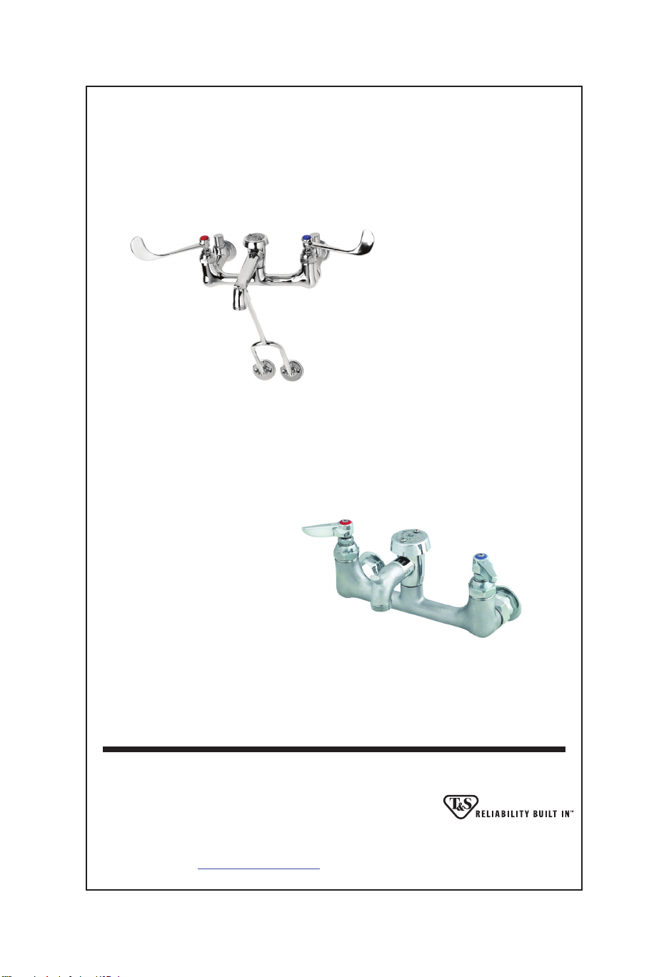
RELATED T&S BRASS PRODUCT LINE
B-0657
Service Sink /
Mop Sink Faucet
B-0674-RGH
Service Sink /
Mop Sink Faucet
T&S BRASS AND BRONZE WORKS, INC.
A fi rm commitment to application-engineered plumbing products
Travelers Rest, SC 29690 ‘De Veenhoeve’
Phone: (864) 834-4102 Oude Nieuwveenseweg 84
Fax: (864) 834-3518 2441 CW Nieuwveen
E-mail:
2 Saddleback Cove, P.O. Box 1088, T & S Brass-Europe
[email protected] The Netherlands
 Loading...