

Page 1

866-5TURFEX
© Trynex International 2009 L1302 (REV 002)
1 —
1
© Trynex International
Owner / Operator’s Manual
The Commercial Turf Choice
SPREADERS
This Manual Must Be Read Before Operating The Equipment
CUSTOMER COPY
Warren, Michigan 48089
Protected by the following patents, #6,089,478, #6,088,865, #Des.425,915
and
other pending U.S. and foreign patent applications.
R
TS-300
TS-300-EG
TS-700-E
TS-700-GR
TS-1200-GR
TS-1200-P
TS-700-P
TS-1200-E
Page 2

Table of Contents
R
Spreader Maintenance . . . . . . . . . . . . . . . . . . . . . . . . . . . . . . . . . . . . . . . . . . . . . . . . . . . . . . . . . . . . . . . . . . . . . . . . . . . . . . . . . . . . . .
51
Adjustable Spinner Information . . . . . . . . . . . . . . . . . . . . . . . . . . . . . . . . . . . . . . . . . . . . . . . . . . . . . . . . . . . . . . . . . . . . . . . . . . . . . 36
Spreader Calibration Charts . . . . . . . . . . . . . . . . . . . . . . . . . . . . . . . . . . . . . . . . . . . . . . . . . . . . . . . . . . . . . . . . . . . . . . . . . . . . . . . . . .
39
Troubleshooting Information . . . . . . . . . . . . . . . . . . . . . . . . . . . . . . . . . . . . . . . . . . . . . . . . . . . . . . . . . . . . . . . . . . . . . . . . . . . . . . . .
52-53
Warranty & Warranty Registration . . . . . . . . . . . . . . . . . . . . . . . . . . . . . . . . . . . . . . . . . . . . . . . . . . . . . . . . . . . . . . . . . . .
54-55
TS-700-E / GR / P & TS-1200-E / GR / P Gate Assembly . . . . . . . . . . . . . . . . . . . . . . . . . . . . . . . . . . . . . . . . . . . . . . . . . . . . . . . . . .
32
TS-700-GR / TS-1200 GR Main Assembly . . . . . . . . . . . . . . . . . . . . . . . . . . . . . . . . . . . . . . . . . . . . . . . . . . . . . . . . . . . . . . 24-25
TS-700-GR & TS-1200-GR Drive Assembly . . . . . . . . . . . . . . . . . . . . . . . . . . . . . . . . . . . . . . . . . . . . . . . . . . . . . . . . . . . . . . . . . .
30-31
Calibration Speed Chart . . . . . . . . . . . . . . . . . . . . . . . . . . . . . . . . . . . . . . . . . . . . . . . . . . . . . . . . . . . . . . . . . . . . . . . . . . . . . . . . . . . . .
37
Calibration Disclaimer . . . . . . . . . . . . . . . . . . . . . . . . . . . . . . . . . . . . . . . . . . . . . . . . . . . . . . . . . . . . . . . . . . . . . . . . . . . . . . . . . . . . . . .
38
. TPM-175 Three Point Mount
Blank Page . . . . . . . . . . . . . . . . . . . . . . . . . . . . . . . . . . . . . . . . . . . . . . . . . . . . . . . . . . . . . . . . . . . . . . . . . . . . . . . . . . . . . . . . . . . . . . .
40-41
Blank Page . . . . . . . . . . . . . . . . . . . . . . . . . . . . . . . . . . . . . . . . . . . . . . . . . . . . . . . . . . . . . . . . . . . . . . . . . . . . . . . . . . . . . . . . . . . . . . .
34-35
Introduction . . . . . . . . . . . . . . . . . . . . . . . . . . . . . . . . . . . . . . . . . . . . . . . . . . . . . . . . . . . . . . . . . . . . . . . . . . . . . . . . . . . . . . . . . . . 3
General Information and Registration . . . . . . . . . . . . . . . . . . . . . . . . . . . . . . . . . . . . . . . . . . . . . . . . . . . . . . . . . . . . . . . . . . . . . . . . . . . . 4
Safety Information . . . . . . . . . . . . . . . . . . . . . . . . . . . . . . . . . . . . . . . . . . . . . . . . . . . . . . . . . . . . . . . . . . . . . . . . . . . . . . . . . . . . . . .
TS-300-E / TS-300-EG Main Assembly . . . . . . . . . . . . . . . . . . . . . . . . . . . . . . . . . . . . . . . . . . . . . . . . . . . . . . . . . . . . . . . . . . . . . . . . . .
TS-700-E / P Main Assembly . . . . . . . . . . . . . . . . . . . . . . . . . . . . . . . . . . . . . . . . . . . . . . . . . . . . . . . . . . . . . . . . . . . . . . . . . . 22-23
TS-1200-E / P Main Assembly . . . . . . . . . . . . . . . . . . . . . . . . . . . . . . . . . . . . . . . . . . . . . . . . . . . . . . . . . . . . . . . . . . . . . . . . . . . . . .
TS-700-E / P & TS-1200-E / P Drive Assembly . . . . . . . . . . . . . . . . . . . . . . . . . . . . . . . . . . . . . . . . . . . . . . . . . . . . . . . . . . . . . . .
TS-700-E & TS-1200-E Electrical Systems . . . . . . . . . . . . . . . . . . . . . . . . . . . . . . . . . . . . . . . . . . . . . . . . . . . . . . . . . . . . . . . . . . . . . . . . .
5-7
8-21
26-27
28-29
33
Accssories & Mounts . . . . . . . . . . . . . . . . . . . . . . . . . . . . . . . . . . . . . . . . . . . . . . . . . . . . . . . . . . . . . . . . . . . . . . . . . . . . . . . . . . . . .
. SDK-020 Side Deector Kit
. ADF-020 Adjustable Deector Kit
. DRM-175 Drop Mount Receiver
. TLR-175 Trailer Mount
. UTM-175 Utility Mount
. VAR-020 Variable Speed Control Kit (TS-300,TS-700-E & TS-1200-E Only)
. ZTR-175 Zero Turn Radius Mower Mount
42-50
1 — 2
© Trynex International 2009 L1302
Page 3

1 — 3
Introduction
This manual has been designed for your help. It will assist you and instruct you on the proper set-up, installation and use of
this spreader.
Refer to the table of contents for an outline of this manual.
We require that you read and understand the contents of this manual completely (especially all safety information) before
attempting any procedure contained herein.
THIS SIGN SHOULD ALERT YOU:
The Society of Automotive Engineers has adopted this SAFETY ALERT SYMBOL to pinpoint characteristics
that, if NOT carefully followed, can create a safety hazard. When you see this symbol in this manual or on the
machine itself, BE ALERT! Your personal safety and the safety of others is involved
.
Dened below are the SAFETY ALERT messages and how they will appear in this manual:
(RED)
Information that, if not carefully followed,
can cause death!
(ORANGE)
Information that, if not carefully followed,
can cause serious personal injury or death!
(YELLOW)
Information that, if not carefully followed,
can cause minor injury or damage to equipment.
R
© Trynex International 2009 L1302
Page 4

© Trynex International 2009 L1302
1 — 4
General Information
CONGRATULATIONS!
The Turfex product you have purchased is an example of turf management product at its nest! Your Turfex product’s, self
contained design is a trademark of all Turfex products. Here’s why...
SIMPLICITY: Fewer moving parts manufactured of higher quality means minimal maintenance for your Turfex product.
RELIABILITY:
High impact linear low density polyethelyne hopper, state-of-the-art electronic dual variable speed control, custom engineered
powder coated frame, maximum torque 12 volt motor coupled to a custom engineered transmission found only on Turfex products.
VERSATILITY:
Multi-use capabilities allows spreading of a variety of materials.
WARRANTY:
Two years parts and labor from date of installation.
The benets you are about to recognize are that of time, money and eort.
We welcome you to the world of Turfex Performance.
Registration
Record the following information in this manual for quick reference.
Spreader
Model Number _____________________________________________________________________________________
Serial Number ________________________________ Controller Serial Number ____________________________________
Date of Purchase ___________________________________________________________________________________________
Dealer Where Purchased _____________________________________________________________________________________
When ordering parts, the above information is necessary. This will help to insure
that you receive the correct parts.
At the right is a diagram of the ID tag. This tag is located on the frame
(where applicable).
Please ll out the warranty card with all the necessary information to validate it. This will also give us a record so that
any safety or service information can be communicated to you.
SER. NO.______________________
TRYNEX INTERNATIONAL
Warren, MI 48089 (800) 725-8377
R
R
Page 5

1 — 5
Safety
Before attempting any procedure in this book, these safety instructions must be read and understood by all workers who
ha
ve any part in the preparation or use of this equipment.
For your safety warning and information decals have been placed on this product to remind the operator of safety precautions.
If anything happens to mark or destroy the decals, please request new ones from Trynex.
Unit must be strapped down and locked into position before operating vehicle.
Never exceed the Gross Vehicle Weight Rating of vehicle. Failure to do so may limit a vehicles
handling characteristics.
Never attempt to take a unit o with material in it.
Do not drive at excessive speeds when loaded spreader is attached to vehicle. Braking distances may
be decreased and handling characteristics may be impaired at higher speeds.
Never allow children to operate or climb on equipment.
Always check areas to be spread to be sure no hazardous conditions or substances are in the area.
Always inspect unit for defects: broken, worn or bent parts, weakened areas on spreader or mount.
Always shut o vehicle and power source before attempting to attach or detach or service spreader
unit. Be sure vehicle/power source is properly braked or chocked.
Always keep hands, feet, and clothing away from power-driven parts.
Remember
it is the owner’s
responsibility to communicate information on safe usage and proper maintenance of all equipment.
Always make sure personnel are clear of areas of danger when using equipment. Maintain 60'
distance from all bystanders when operating the spreader.
Inspect the unit periodically for defects. Parts that are broken, missing, or worn out must be replaced
immediately. The unit, or any part of it should not be altered without prior written permission from
the manufacturer.
Never use with foreign debris in the spreader. These units are designed to handle clean,
free-owing material.
Note: Can not spread water softner salt.
R
© Trynex International 2009 L1302
Page 6

© Trynex International 2009 L1302
1 — 6
Safety
(continued)
Al
ways inspect pins and latches whenever attaching or detaching spreader, and before traveling.
Never leave material in hopper for long periods of time. Be aware that all ice melters and fertilizers
are hygroscopic and will attract atmospheric moisture and harden up.
Remember, most accidents are preventable and caused by human error.
Exercising of care and
precautions must be observed to prevent the possibility of injury to operator or others!
Never operate equipment when under the inuence of alcohol, drugs, or medication that might alter your
judgment and/or reaction time.
Before working with the spreader, secure all loose tting clothing and unrestrained hair.
Always wear safety glasses with side shields when servicing spreader. Failure to do this could result in
serious injury to the eyes.
R
Page 7

© Trynex International 2009 L1302
1— 7
Safety and Warning Labels
D 6546
D 6548
D 6335
D 6544
D 6545
D 6859
All Turfex products have warning labels instructing you about certain safety issues you should be aware of. Below are
examples of what to look for and familiarize yourself with. In the event that a label is lost or removed for renishing
reasons, you may obtain new ones from Turfex.
R
Page 8

© Trynex International 2009 L1302
1 — 8
TS-300
Main Assembly Views
R
Page 9
© Trynex International 2009 L1302
1 — 9
TS-300
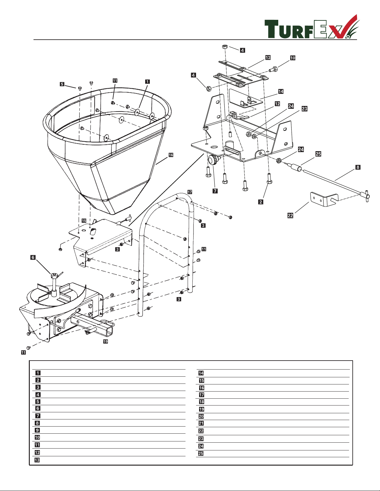
Exploded View
R
.ytQ noitpircseD .oN traP yeK
D 4318 3/8" Fender Washer 4
T 15049 5/16-18 x 1/2” Hex Bolt SS 2
14 utnkcoL "61/5 8316 D
1 t SSuN xeH 61 - "61/5 8616 D
1 bonK etaG 2036 D
.ytQ noitpircseD .oN traP yeK
1
kcarT etaG redeeS
e 1dilS etaG redeeS 5076 D
4076 D
1 reppoH redeeS 051 9076 D
D 6418 5/16" - 18 x 1" Hex Bolt SS 2
D 6304 T-Handle Cable - 10' 1
D 6305 Bulkhead Cable Fitting 1
D 6308 5/16" - 16 x 3/4" Bolt w/Hole SS 1
D 6462 5/16" - 18 x 1-3/4" HHCS 12
D 6703 Gate Indicator / Stop 1
D 6706 Seeder 400 Gate Deck 1
D 6712 Hopper Tube Support 1
D 6480 Transmission Weldment 1
D 6485 Light Duty Receiver Mount 1
D 4116 1/2"-13 x 1-1/2" Hex Bolt 4
4 tuN kcoL "2/1 0214 D
1 T 15036
Cable Mounting Bracket
T 15051
T 15052
T 15050
3/8 Internal Star Lock Washer
3/8-24 Jam Nut SS
C
able Fitting
1
1
1
D 6705 Agitator 1
Page 10

© Trynex International 2009 L1302
Assembly Instructions (refer to digram on page 1-9)
Step
1: Attach hopper tube support (D 6712)
to complete drive assembly using (4) 5/16"-18 x 1-3/4" hex bolt (D 6462)
and (4)
5/16" lock nut (D 6138)
. Use (2) holes at bottom end of tube.
Step 2: Place spreader gate deck (D 6706) upside down on table.
Step 3: Assemble gate indicator/stop (D 6703)
on stop slide with gate knob (D6302)
. Gate stop must be on the inside of deck where
it will stop the track.
Step 4: Insert (1) 5/16 bolt with hole (D 6308)
through gate slide (D 6705)
. Finger tighten (1) 5/16" locknut (D 6138)
on bolt.
Step 5: Take bulkhead cable tting (D 6305)
and screw it onto T-handle cable - 10' (D 6304)
rubber coating.
Step 6: Place assembly through tab on gate deck. Tighten down with supplied washer and nuts.
NOTE: There should be a nut on either
side of tab.
Step 7: Lower gate assembly over spinner shaft. Spinner shaft must go through 5/8" hole on deck. Shaft to be centered in hole.
Step 8: Fasten deck to hopper tube using (4) 5/16" hex bolts (D 6462)
and (4) 5/16" locknuts (D 6138)
NOTE: You must rst
tighten bottom bolts, pull front of deck up, then tighten top set of bolts.
Step 9: Place hopper (D 6709)
on deck. 5/8" hole must be used for spinner shaft.
Step 10: Finger tighten (2) 5/16 x 1" bolts (D 6166)
through bottom of hopper.
Step 11: Place (4) at washers (D 4318)
over hex bolts (D 6462). Place bolts through hopper back and in through tube support.
Tighten with (4) 5/16" locknuts.
Step 12: Tighten bolts in bottom of hopper.
Step 13: Place agitator (D 6405) on spinner shaft. Tighen to middle of at with short allen key.
Step 14: Attach receiver mount (D 6485) to transmission weldment (D 6480) using (4) 1/2" hex bolts (D 4116) and (4) 1/2" lock
nuts (D 4 120).
CABLE INSTALLATION
Step 1: Place unit on vehicle where it will be permanently used. Place hitch pin in hitch so unit does not move.
Step 2: Route T-handle to desired operating location. There cannot be any bends or sharp corners.
Step 3: Take T-handle out of sleeve. Take nuts and washer o of sleeve.
Step 4: Drill holes to mount T-handle mounting bracket. Mount T-Handle to bracket.
Step 5: Close gate slide all the way.
Step 6: Re-insert cable handle and wire all the way. Aim through bolt with hole and tighten bolt.
1 — 10
TS-300
R
Page 11

© Trynex International 2009 L1302
1 — 11
TS-300
Wiring Diagram
R
TS-300 Wiring Instructions
Step 1: First, install switch at desired location.
Step 2: Run spreader/vehicle harness from the rear of vehicle to switch area. Attach the female spade red wire to the switch. Leave the
black wire for Step 5.
Step 3: Route the power harness from the battery to the switch/control.
Step 4: Attach the red lead to the positive side of the battery and the black lead to the negative side of the battery.
Step 5: Attach the female spade red wire on switch terminal. Using 3" double female black wire jumper attach the black wire from the
power harness to the black wire of the vehicle harness.
Step 6: Install rubber weatherproof boot on switch before nishing installation.
Step 7: Insert dielectric grease on terminals of SAE plug at rear of vehicle.
20
AMP
BATTERY
REMOVE JUMPER FOR USE
WITH VC-020 VARIABLE
SPEED CONTROLLER
DOUBLE FEMALE
3" JUMPER
Key Part No. Description Qty.
D 6184 On/O Switch 1
D 6406 Rubber Switch Boot 1
D 6716 Wiring Harness 1
D 6425 Fuse Holder 1
D 6482 20 Amp Fuse 1
D 7105 3/8" Ring Terminal 1
Page 12
© Trynex International 2009 L1302
1 — 12
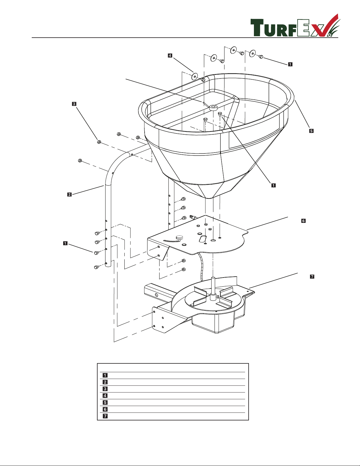
TS-300-EG
Main Assembly Breakdown
R
.ytQ noitpircseD .oN traP yeK
D 4318 3/8" Fender Washer
14
14
8316 D
D 6462 5/16" - 18 x 1-3/4" HHCS
5/16" Lock Nut
1 2.7 Cu/Ft Seeder Hopper Yellow 6753 D
1
Electric Gate Assembly
Drive Assembly
1
D 6712 Hopper Tube Support 1
4
SEE DRIVE EXPLODED
VIEW
SEE GATE EXPLODED
VIEW
SEE DRIVE EXPLODED
VIEW
Page 13
TS-300-EG / TS-300
R
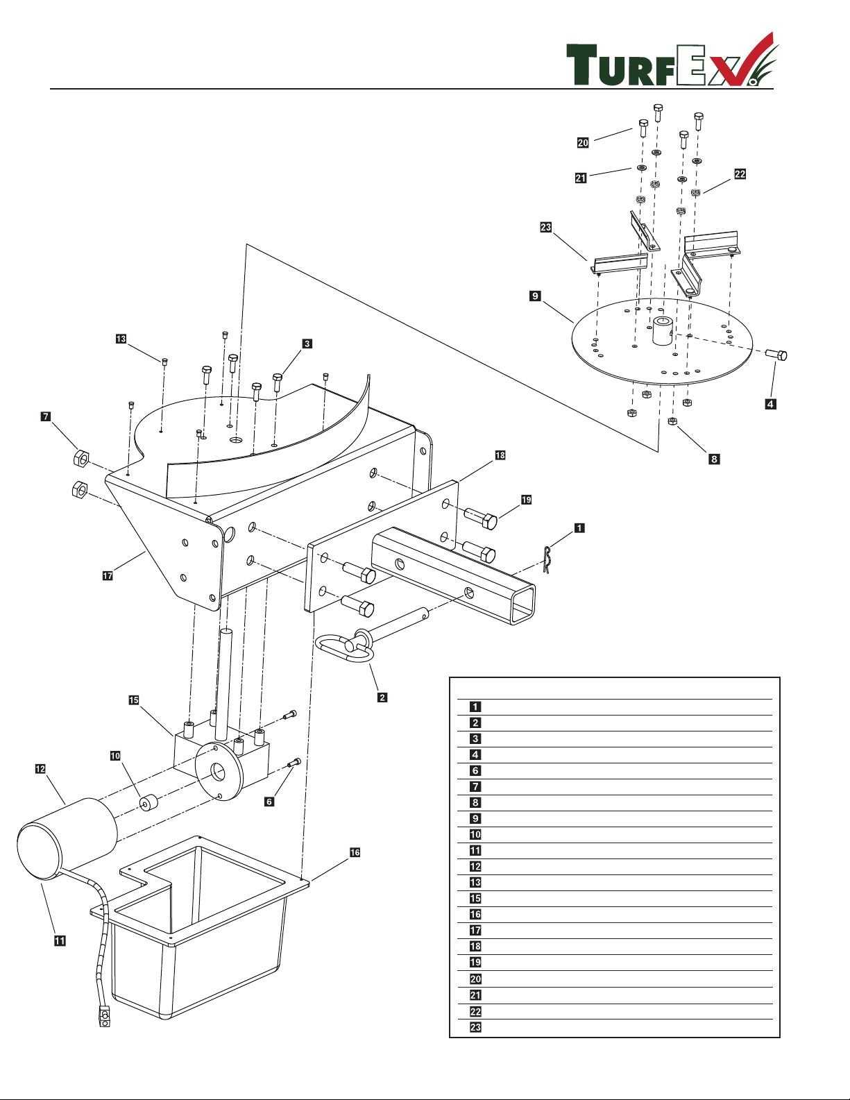
Drive Assembly
Key Part No. Description Qty.
D 4135 2-5/16" Hair Pin Clip 1
D 4136 5/8" x 5-1/2" Hitch Pin 1
D 6131 1/4"-20 x 1/2" Serr. Flange Bolt 4
D 6133 5/16-18 x 1/2 HHCS 1
D 6172 #10-32 x 5/8" Serr Flange Bolt 2
10 Inch Spinner Plate 1
D 6232 Motor Drive Coupler 1
D 6410 Motor 12 Volt DC (TS-300 Motor) 1
D 6487 #8 x 1/2" Hex Head Sheet Screw 5
D 6715 Transmission 14.5 to 1 1
D 7153 Plastic Bottom Cover 1
D 6480 Transmission Weldment 1
D 6485 Light Duty Receiver Mount 1
D 4116 1/2"-13 x 1-1/2" Hex Bolt 4
1/4-20 x 1-1/4 Panhead MSSS 4
D 4120 1/2" Lock Nut 4
T 30218
T 15014
T 30217
T 15031
T 15016
1/4 Flat Washer SS 4
Tension Spring 4
Adjustable Flite 4
1/4-20 Nylock Nut SS 4
D 6106
Motor 12 Volt (TS-300-EG) 4
T 15030
Complete Drive Assembly Part Number A-4039
( Note: Does Not Include Hich Mount )
© Trynex International 2009 L1302
1 — 13
Page 14
TS-300-EG
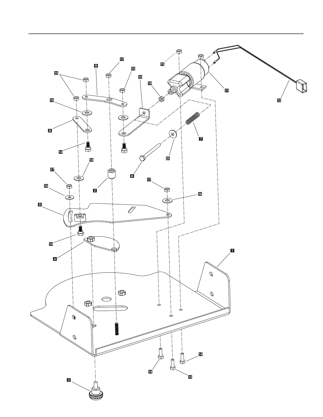
Electric Gate Control System
1 — 14
© Trynex International 2009 L1302
Page 15
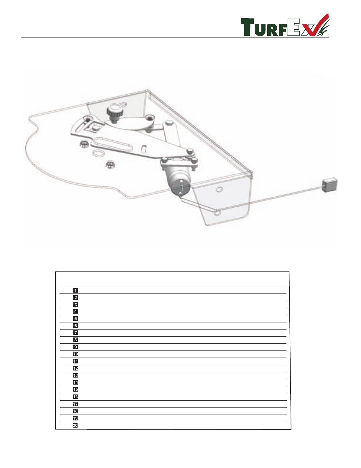
TS-300-EG GATE
R
.ytQ noitpircseD .oN traP yeK
1
T-15029 Gate Stop Knob
T-15001 Gate Deck
T-15003 Gate Stop
T-15002 Gate Slide
T-15012 1/4-28 x 3 SHCS SS
T-15009 Stainless Spring
T-15007 Stainless Arm #3
T-15006 Stainless Arm #2
T-15005 Stainless Arm #1
T-15008 12 Volt Actuator
T-15020 Actuator Power Cord
D 6166 5/16-18 x 1 Hex Bolt
T-15021 1/4-20 x 3/4 PPH MS Stainless
T-15016 1/4-20 Nylock Stainless
1
1
1
1
1
1
1
1
1
1
1
1
5
4
T-15017 5/16 Nylon Flat Washer
T-15018 5/16-18 Nylock Stainless
T-15023 1/4” Nylon Flat Washer
T-15013 1/4-28 Jam Nut Stainless
T-15014 1/4” Flat Washer Stainless
2
4
3
1
1
T-15037 Gate Stop Spacer
Parts Breakdown
© Trynex International 2009 L1302
1 — 15
Page 16
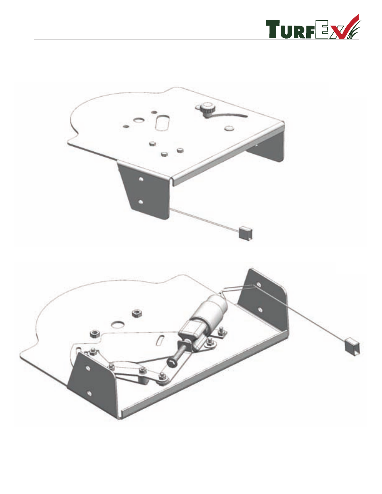
TS-300-EG
R
Gate Assembly Views
1 — 16
© Trynex International 2009 L1302
Page 17
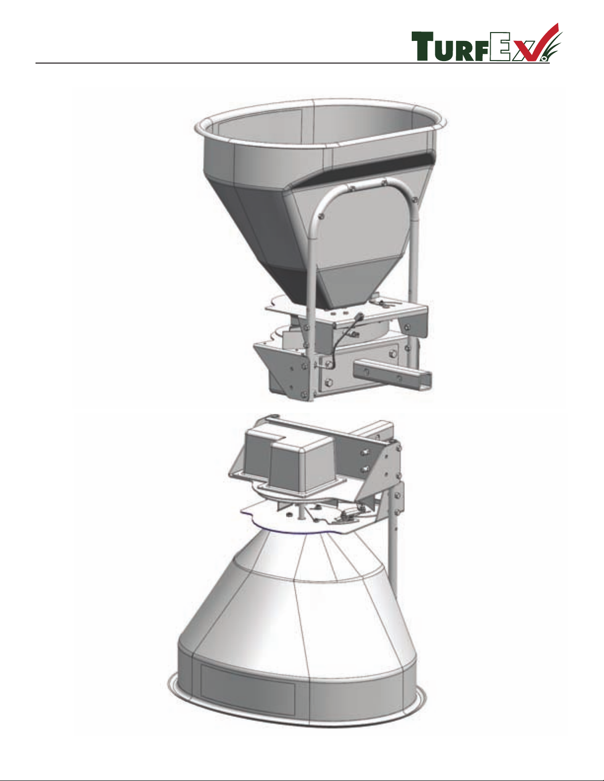
TS-300-EG
R
Front & Rear Assembly Views
© Trynex International 2009 L1302
1 — 17
Page 18
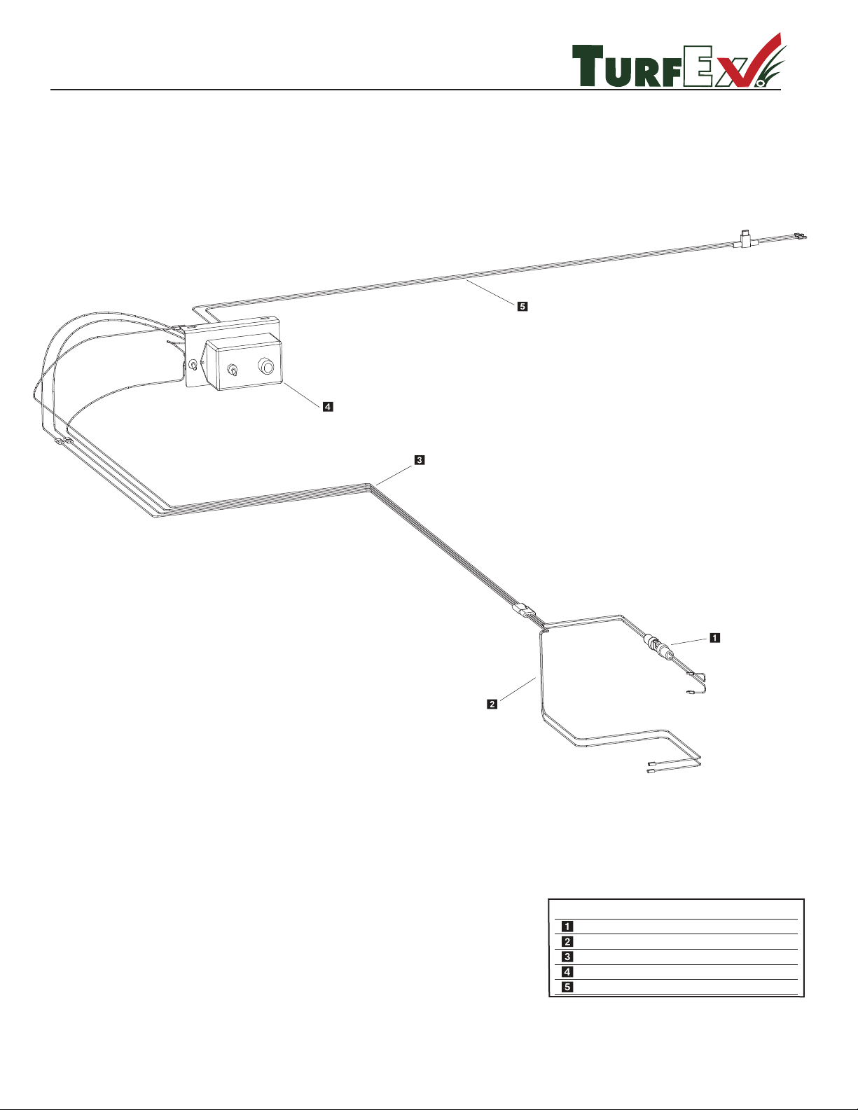
© Trynex International 2009 L1302
1 — 18
TS-300-EG
Electrical System Overview
Key Part No. Description Qty.
T 15020 SOLENOID WHIP 1
T 15034 SPREADER HARNESS 1
T 15028 VEHICLE HARNESS 1
D 7171 CONTROL 1
T 15011 BATTERY HARNESS 1
R
Page 19
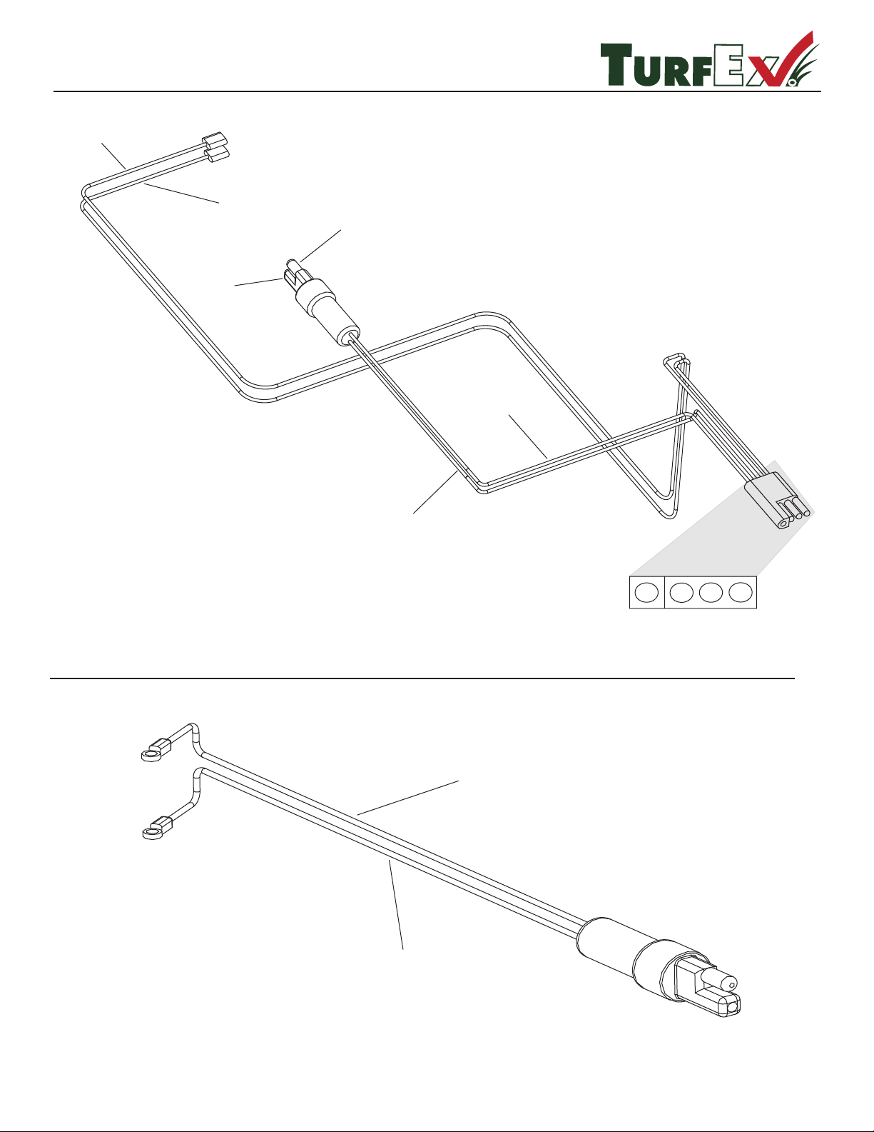
© Trynex International 2009 L1302
1 — 19
Parts Breakdown
TS-300-EG Solenoid Power Cord T 15020
TS-300-EG Spreader Harness T 15034
BLU (+) POS
GRN (-) NEG
BLK (-) NEG
RED (+) POS
BLK
RED BLU
GRN
(-)
(+)
RED (+) POS
BLK (-) NEG
R
Page 20
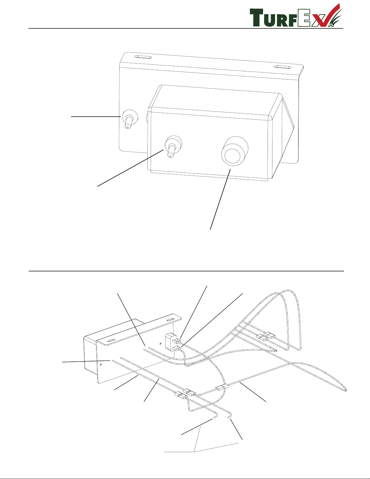
© Trynex International 2009 L1302
1 — 20
R
TS-300-EG Control Back View
TS-300-EG Control Front View D 7171
GATE SWITCH
ON/OFF
SPREADER POWER
ON/OFF
SPINNER SPEED
CONTROL
POWER IN
POWER OUT
RED (+) POS
ORG (-) NEG
BLUE (-) NEG
BLK (-) NEG
BLK (-) NEG
RED (+) POS
RED (+) POS
TO BATTERY
Page 21
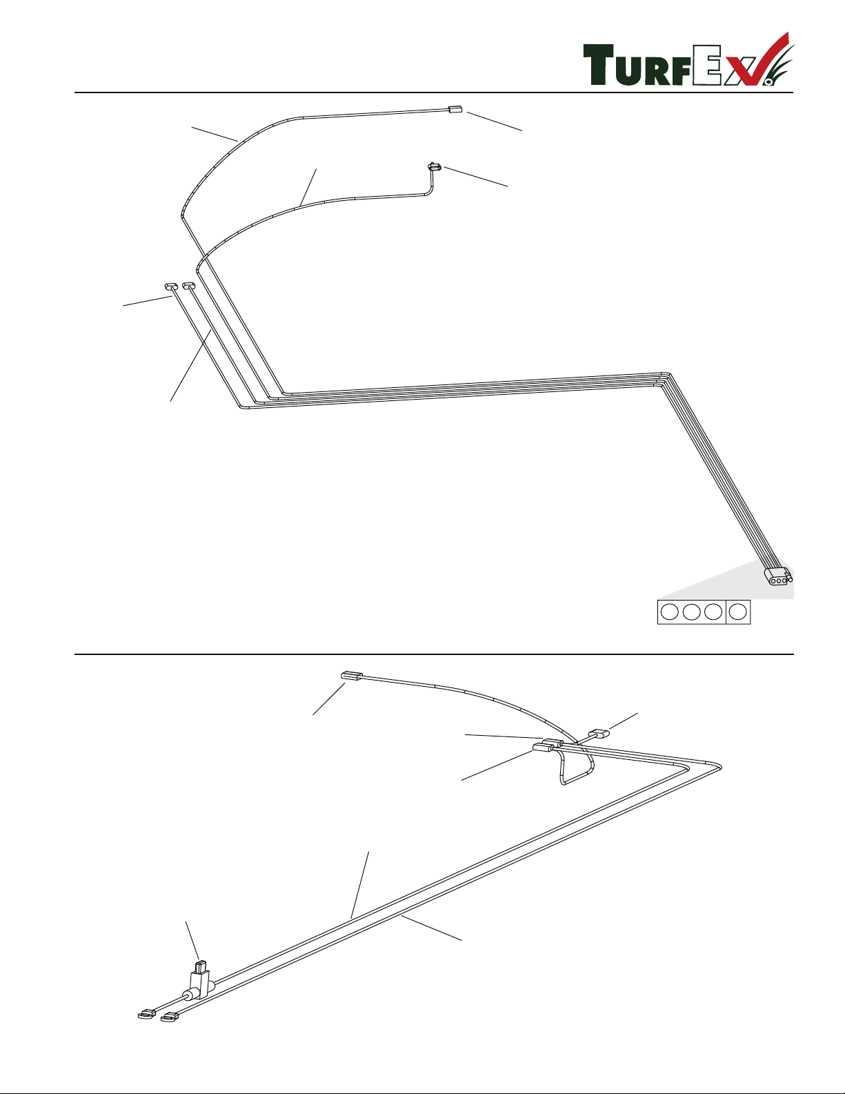
© Trynex International 2009 L1302
1 — 21
R
TS-300-EG Battery Harness T 15011
TS-300-EG Vehicle Harness T 15028
CONNECT TO BLK (-) NEG
BATTERY HARNESS
CONNECT TO GATE
SWITCH
ORG (+) POS
BLUE (-) NEG
BLK (-) NEG
RED (+) POS
BLK RED
ORG BLU
20 AMP
MINI FUSE
RED (+) POS
BLK (-) NEG
CONNECT TO
GATE SWITCH (+)
CONNECT TO
BLUE WIRE (-)
POWER IN (+)
POWER IN (-)
Page 22
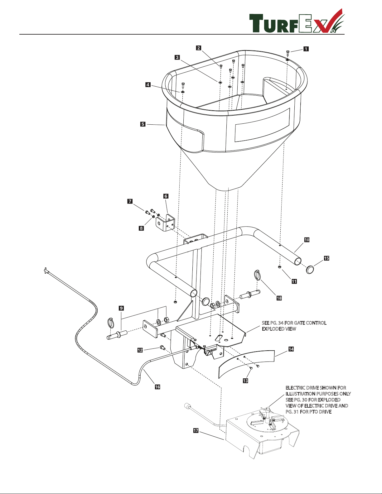
TS-700-E / TS-700-P
R
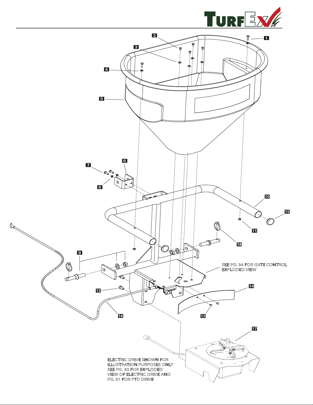
ELECTRIC DRIVE SHOWN FOR
ILLUSTRATION PURPOSES ONLY
SEE PG. 30 FOR EXPLODED
VIEW OF ELECTRIC DRIVE AND
PG. 31 FOR PTO DRIVE
SEE PG. 34 FOR GATE CONTROL
EXPLODED VIEW
Main Frame Assembly
1 — 22
©
Trynex International 2009 L1302
Page 23
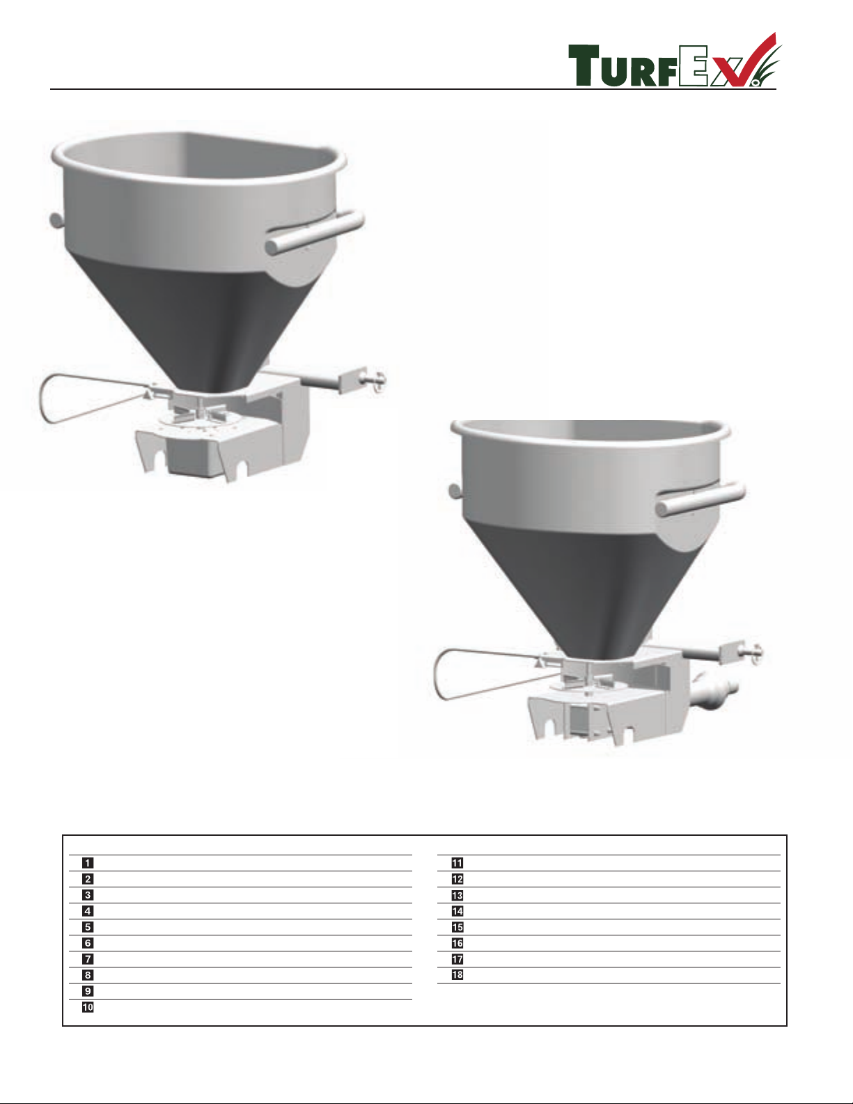
© Trynex International 2009 L1302
1 — 23
TS-700-E / TS-700-P
.ytQ noitpircseD
.oN traP
yeK
.ytQ noitpircseD
.oN traP
yeK
D 5724 3/8-16 x 1-3/4 HHCS
5/16-18 X 1-1/4 HHCS
5/16 USS Flat Washer
3/8 USS Flat Washer
Hopper
Clevis Three Point Bracket
3/8-16 x 1 HHCS
3/8 Lock Washer
Lift Arm Pin Assembly
Frame Weldment
3/8-16 Lock Nut
1/2-13 x 1 Flange Bolt
Large Plastic Push Pin
Plastic Deector
Plastic Tube End Cap
Complete Gate Assembly (see pg 29)
Complete Drive Assembly (see pg 26)
5/16 Lynch Pin
2
4
4
2
1
1
2
2
2
1
2
4
2
1
2
1
1
2
D 6576
D 6165
D 4125
T 30200
T 30204
D 4121
D 4313
D 4137
T 30203
D 4124
D 6528
D 6463
D 6110
T 30219
A 6223
D 4133
R
Assembly Views
TS-700-E
TS-700-P
Page 24
TS-1200-E / TS-1200-P
R
ELECTRIC DRIVE SHOWN FOR
ILLUSTRATION PURPOSES ONLY
SEE PG. 30 FOR EXPLODED
VIEW OF ELECTRIC DRIVE AND
PG. 31 FOR PTO DRIVE
SEE PG. 34 FOR GATE CONTROL
EXPLODED VIEW
Main Frame Assembly
1 — 24
©
Trynex International 2009 L1302
Page 25
© Trynex International 2009 L1302
1 — 25
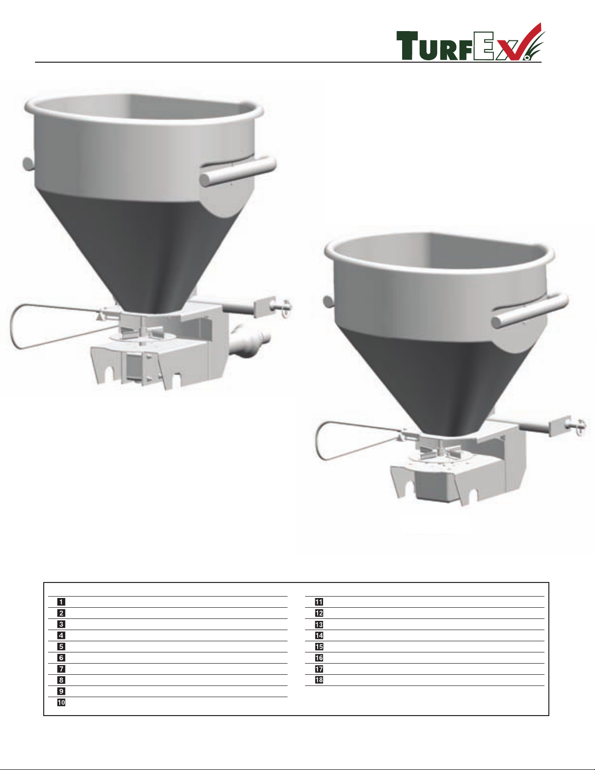
TS-1200-E / TS-1200-P
R
Assembly Views
TS-1200-P
TS-1200-E
.ytQ noitpircseD
.oN traP
yeK
.ytQ noitpircseD
.oN traP
yeK
D 5724 3/8-16 x 1-3/4 HHCS
5/16-18 X 1-1/4 HHCS
5/16 USS Flat Washer
3/8 USS Flat Washer
Hopper
Clevis Three Point Bracket
3/8-16 x 1 HHCS
3/8 Lock Washer
Lift Arm Pin Assembly
Frame Weldment
3/8-16 Lock Nut
1/2-13 x 1 Flange Bolt
Large Plastic Push Pin
Plastic Deector
Plastic Tube End Cap
Complete Gate Assembly (see pg 29)
Complete Drive Assembly (see pg 31)
5/16 Lynch Pin
2
4
4
2
1
1
2
2
2
1
2
4
2
1
2
1
1
2
D 6576
D 6165
D 4125
T 30300
T 30204
D 4121
D 4313
D 4137
T 30304
D 4124
D 6528
D 6463
D 6110
T 30219
A 6223
D 4133
Page 26
© Trynex International 2009 L1302
1 — 26
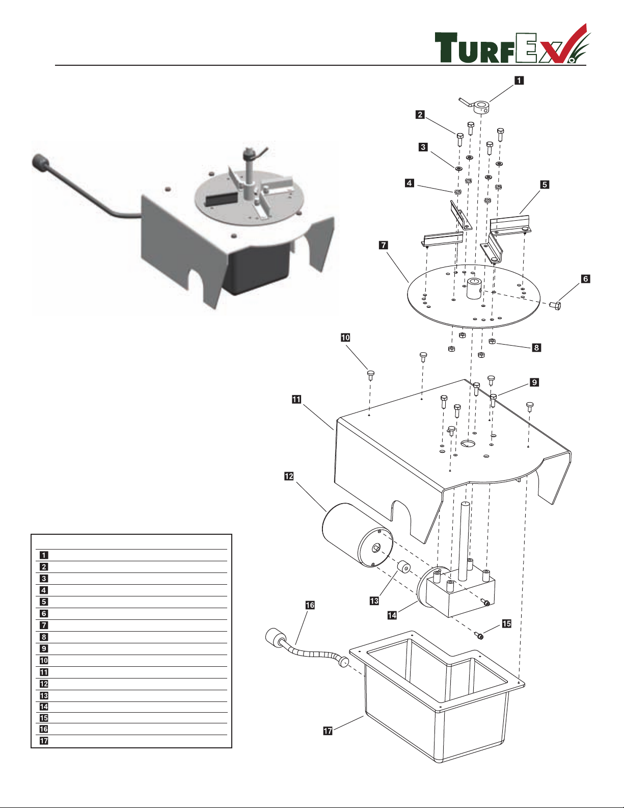
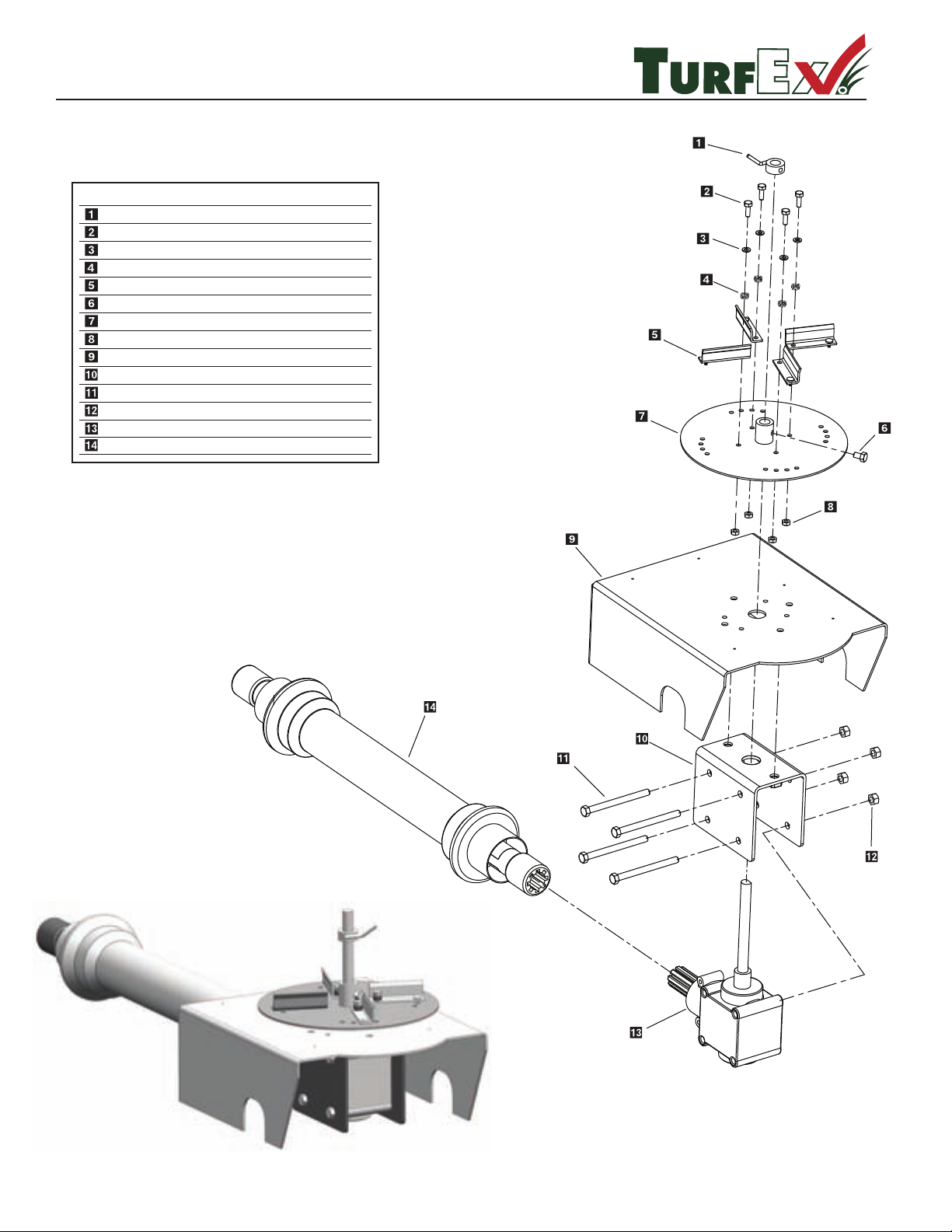
TS-700-E / TS-1200-E
Electric Drive Exploded View
R
Key
D 6405
1/4-20 x 1-1/4 Panhead MS SS
Agitator
3/8 Flat USS Washer
Tension Spring
Adjustable Fin
5/16-18 X 1/2 Hex Bolt
Spinner Plate
1/4-20 Nylock Nut
1/4-20 x 1/2 Serrated Flange
#8 x 1/2 HWH With Slot
Drive Enclosure
12 Volt Spinner Motor
Drive Coupler
T 30218
D 4125
T 30217
T 30211
D 6133
T 30216
D 4289
D 6131
D 6487
T 30208
D 6106
D 6232
1
4
4
4
5
1
1
4
4
5
1
1
1
D 6715
#10-32 x 5/8 Serrated Flange
Spinner Transmission
Power Cord
Plastic Motor Cover
D 6172
D 6115
D 7153
1
2
1
1
Part No.
D
escription Qty.
Page 27
© Trynex International 2009 L1302
1 — 27
TS-700-P / TS-1200-P
PTO Drive Exploded View
R
Key
D 6405
1/4-20 x 1-1/4 Panhead MS SS
Agitator
3/8 Flat USS Washer
Tension Spring
Adjustable Fin
5/16-18 X 1/2 Hex Bolt
Spinner Plate
1/4-20 Nylock Nut
Drive Enclosure
3/8-16 Lock Nut
Pto Transmission
T 30218
D 4125
T 30217
T 30211
D 6133
T 30216
D 4289
T 30208
D 4124
T 30210
1
4
4
4
4
1
1
4
1
1
4
4
1
T 30214
Drive Line Assembly
3/8-16 x 5 HHCS
Transmission Mtg Bracket
T 30206
T 30209
1
Part No.
D
escription Qty.
Page 28
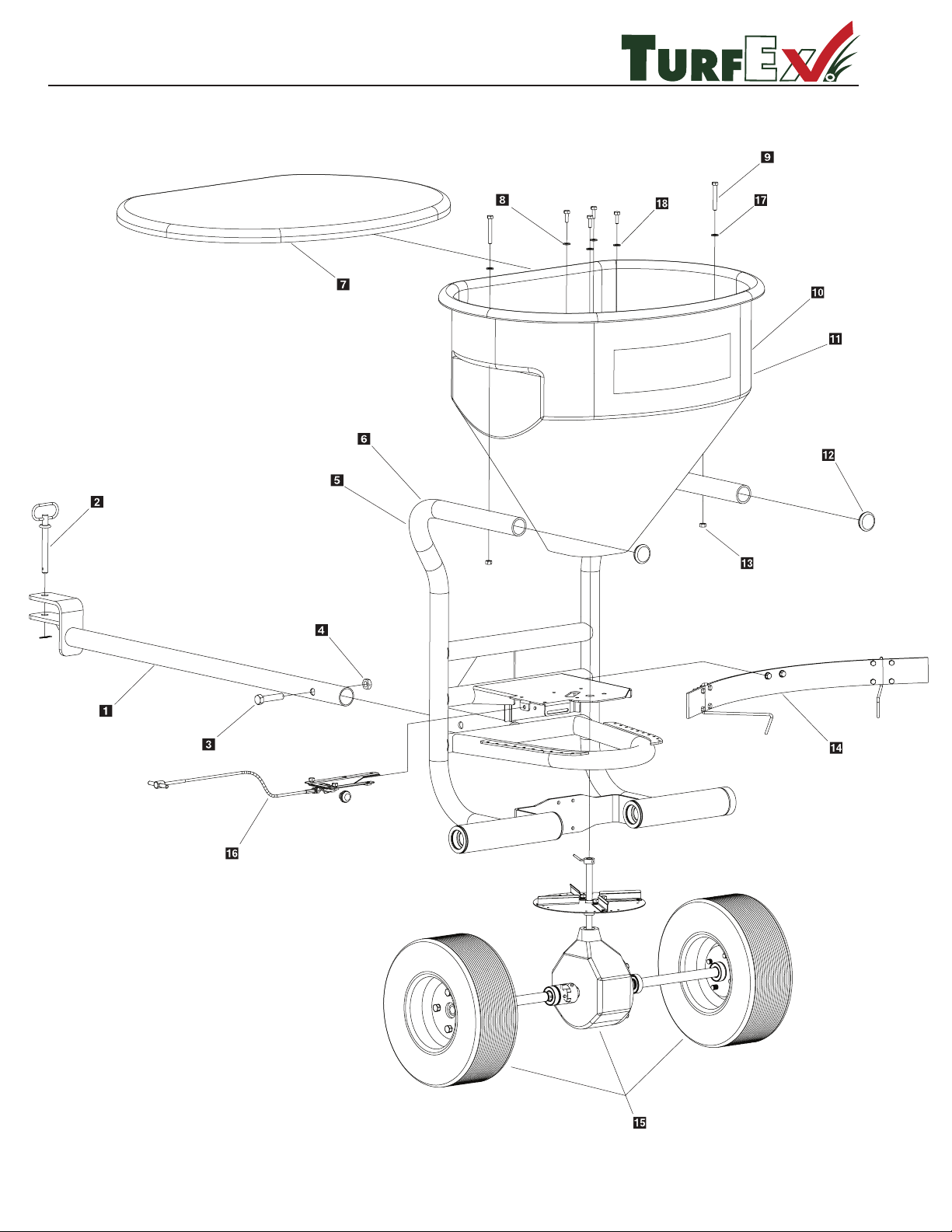
TS-700-GR / TS-1200-GR
R
Main Frame Assembly
1 — 28
© Trynex International 2009 L1302
Page 29
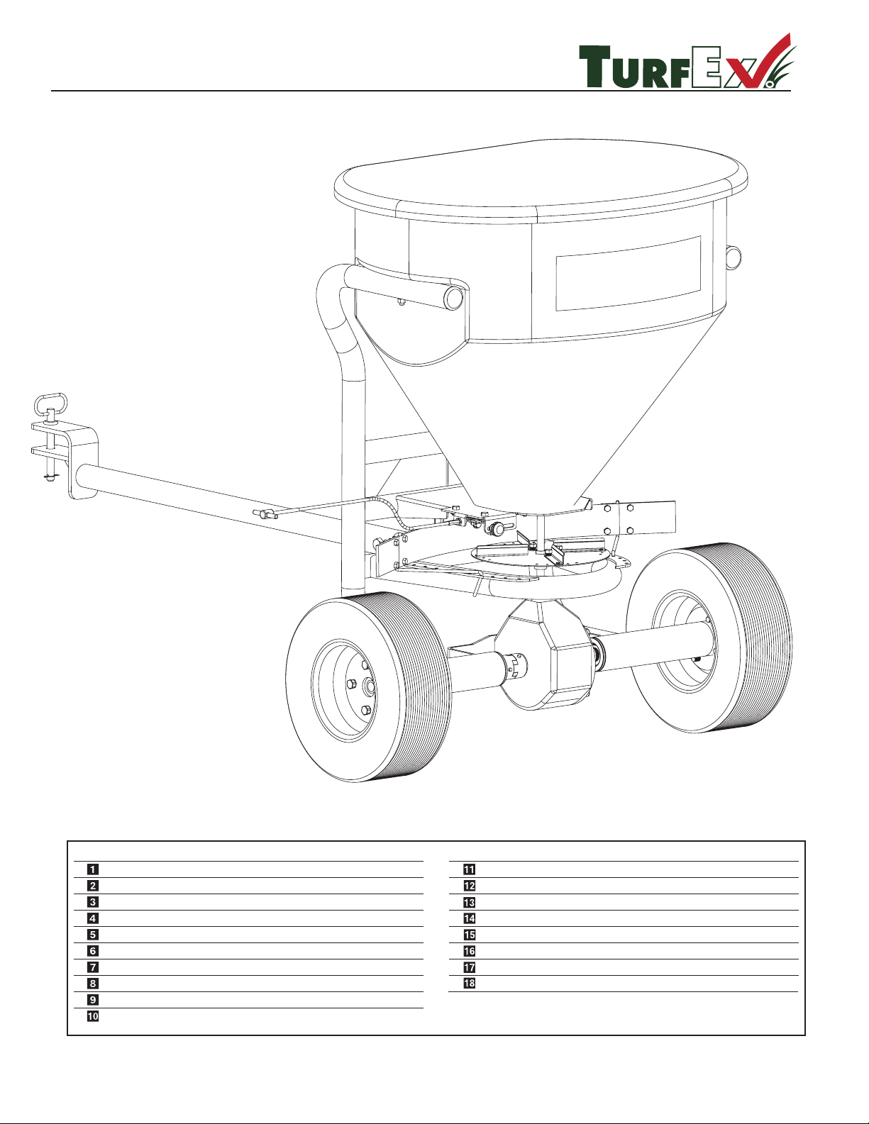
TS-700-GR / TS-1200-GR
R
Assembly Breakdown
.ytQ noitpircseD
.oN traP
yeK
.ytQ noitpircseD
.oN traP
yeK
T 30231 Drawbar
Hitch Pin W/Clip
5/8-11 x 3-1/2 Hex Head
5/8-11 Nylox Nut
700 Series Frame
1200 Series Frame
Clear Cover
5/16-18 x 1-1/4 Phillips Pan Head MS SS
3/8-16 x 2-3/4 Hex Head
1200 Series Hopper
700 Series Hopper
2 Inch Plastic End Cap
3/8-15 Nylox Nut Zinc
Adjustable Deector Assembly (See Pg. 43)
Spinner/Axle Drive Assembly (See Pg. 32,33)
Gate Control Assembly (See Pg. 32)
3/8 Flat Washer Zinc
3/8 Flat Washer SS
1
1
1
1
1
1
1
4
2
1
2
4
2
2
4
D 4136
D 4126
D 4127
T 30225
T 30240
T 30215
D 6137
D 5724
T 30300
T 30200
T 30219
D 4124
D 4125
D 6169
© Trynex International 2009 L1302
1 — 29
Page 30
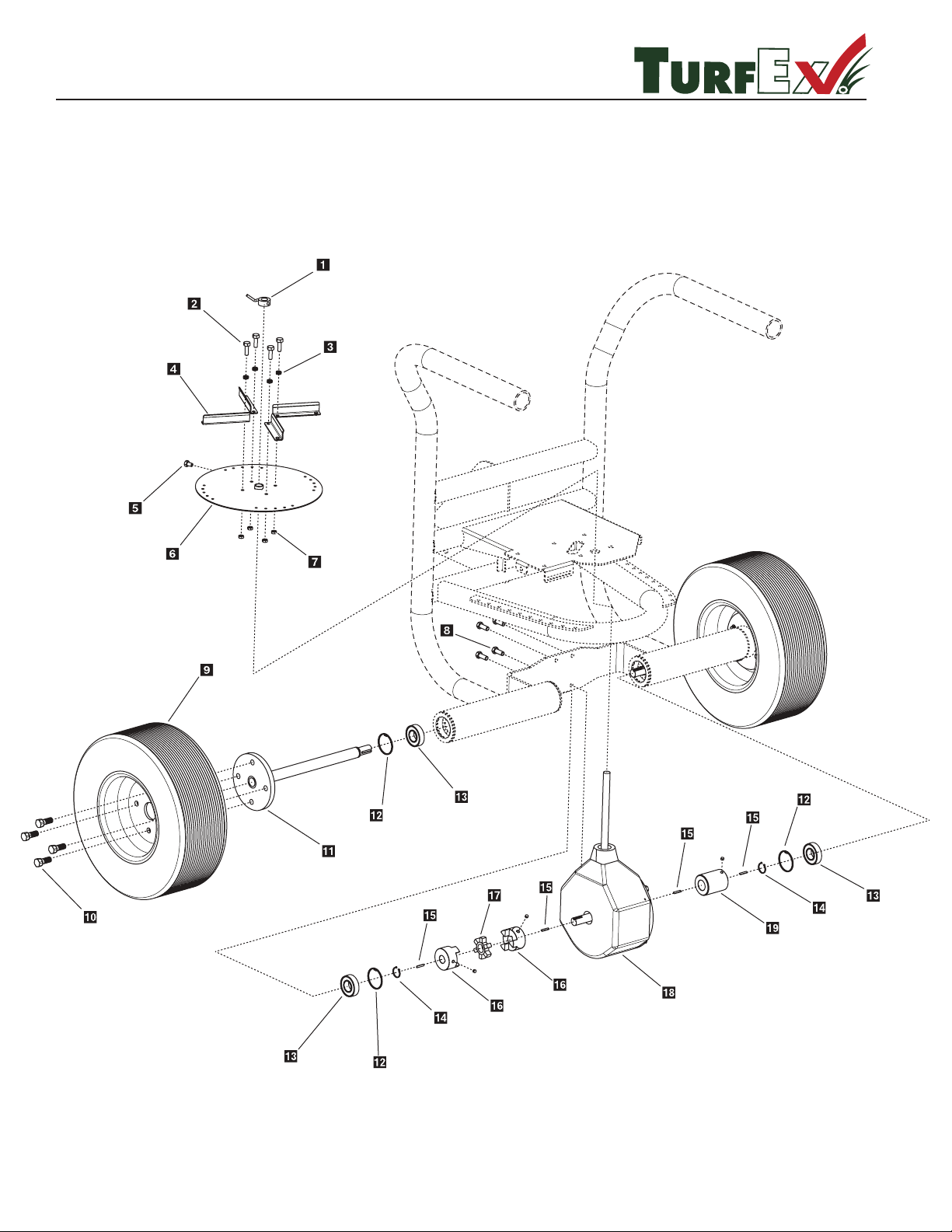
R
TS-700-GR / TS-1200-GR
Drive Assembly
1— 30
© Trynex International 2009 L1302
Page 31
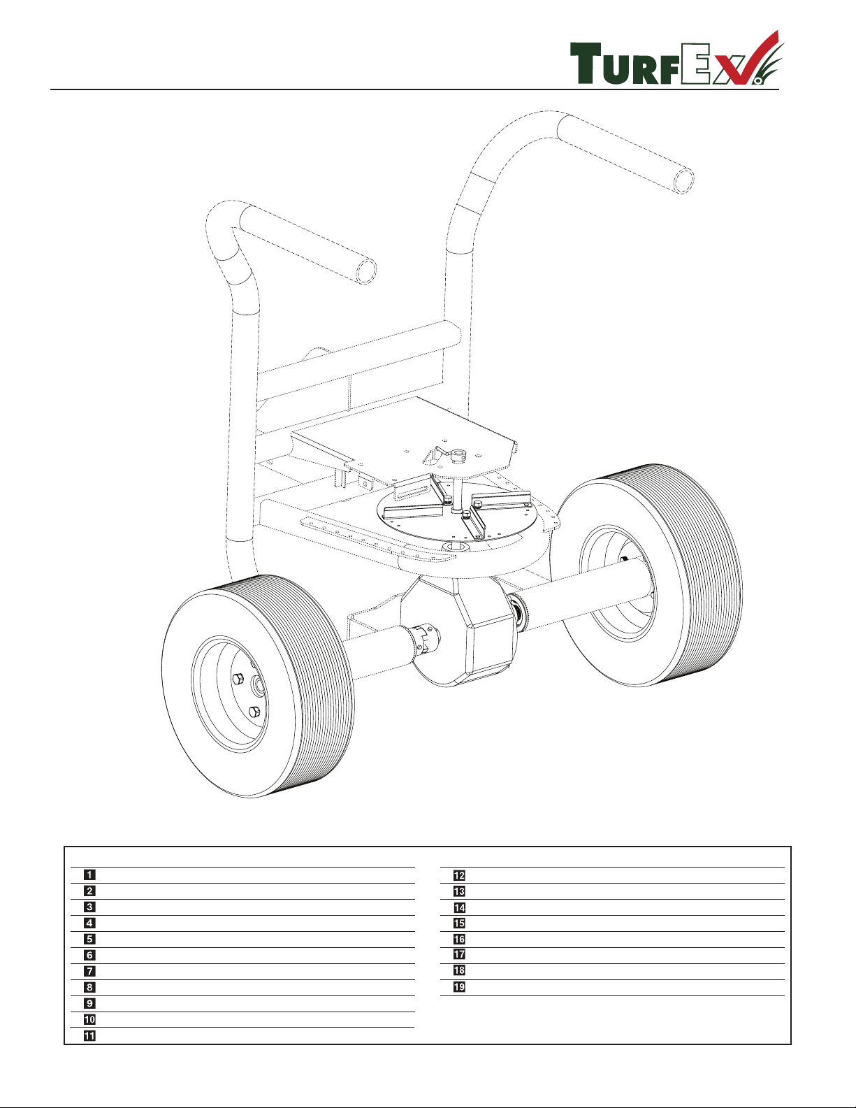
R
TS-700-GR / TS-1200-GR
Parts Breakdown
.ytQ noitpircseD
.oN traP
yeK
.ytQ noitpircseD
.oN traP
yeK
D 6705 Agitator
1/4-20 x 1-1/4 Panhead MSSS
Fin Tension Spring
Adjustable Flite
5/16-18 x 1/2 HHCS
10 Inch Spinner Plate
1/4-20 Nylock Nut SS
5/16-18 x 1-1/4 HHCS
Wheel Assembly
Lug Bolt
Axle
52 mm Bearing Retainer
Bearing
1 Inch Retainer Ring
3/16 Keyway Stock
Lovejoy Coupling
Spyder
Ground Drive Transmission
Coupling
1
4
4
4
1
1
4
4
2
8
2
4
4
2
4
2
1
1
1
T 30218
T 30217
T 30211
D 6133
T 30216
T 15016
D 6576
T 30229
T 30230
T 30227
T 30233
T 30232
T 30234
D 6873
D 6842
D 6843
T 30226
T 30236
© Trynex International 2009 L1302
1— 31
Page 32
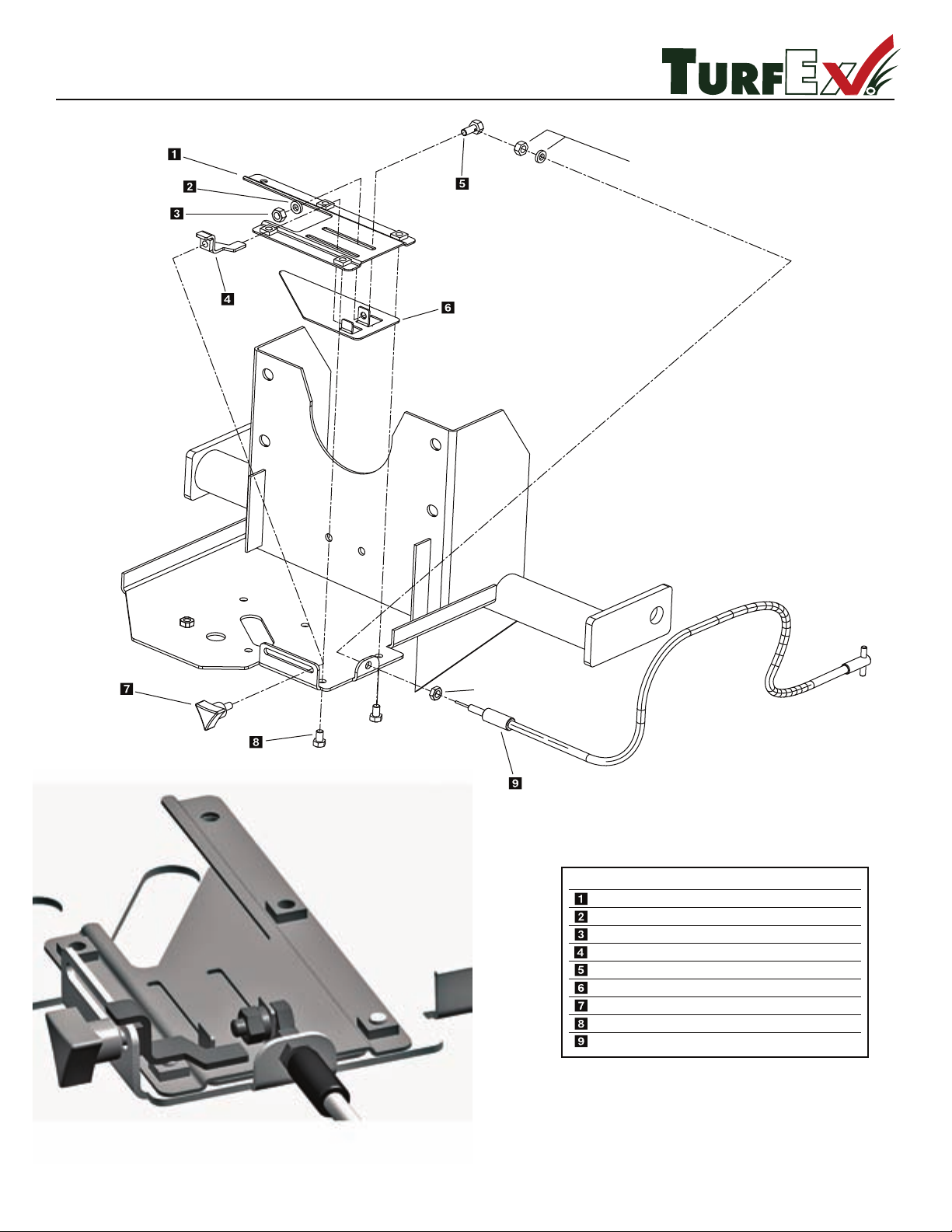
TS-700-E /GR/ P & TS-1200-E /GR/ P
R
Partial frame view for illustration
purposes only.
Key
D 6704
5/16 Lock Washer
Gate Track
5/16 Hex Nut
Gate Stop Bracket
5/16-18 x 3/4 HH With Hole
Gate Slide
Gate Slide Stop Knob
5/16-18 x 1/2 HHCS
10’ T-Handle Gate Cable
D 6155
D 6168
D 6703
D 6308
D 6705
D 6302
D 6133
D 6304
1
1
1
1
1
1
1
2
1
Part No.
D
escription Qty.
ITEMS PART OF CABLE ASSEMBLY
ITEM PART OF CABLE ASSEMBLY
Gate Assembly Exploded View
1 — 32
© Trynex International 2009 L1302
Page 33
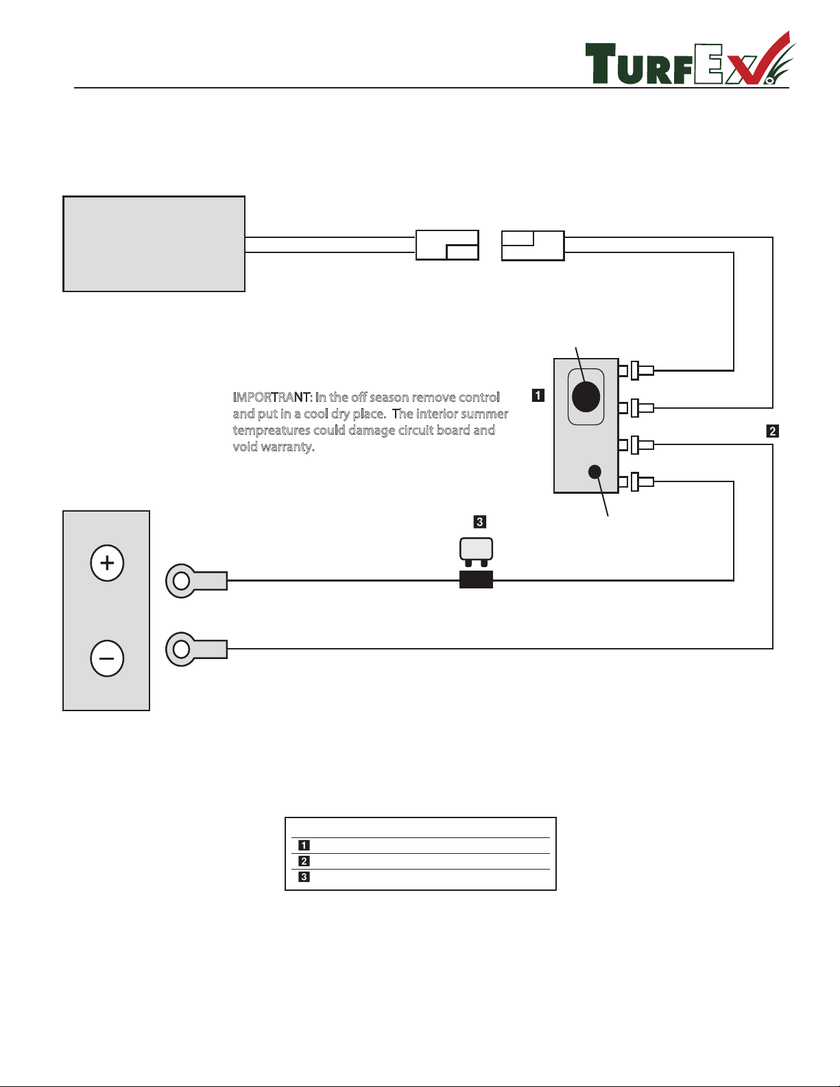
TS-700-E / TS-1200-E
R
Key Part No. Description Qty.
D 7171 Mini Control 1
D 7201 Harness 1
D 6482 20 Amp Breaker 1
20 AMP
(+) Pos.Red
(–) Neg. Black
(–) Neg. Black
(+) Pos.Red
12 VOLT
BATTERY
On/O Switch
Speed Control Knob
SPREADER MOTOR
IMPORTRANT: In the o season remove control
and put in a cool dry place. The interior summer
tempreatures could damage circuit board and
void warranty.
Electrical System
© Trynex International 2009 L1302
1 — 33
Page 34

R
THIS PAGE INTENTIONALY LEFT BLANK
1 — 34
© Trynex International 2009 L1302
Page 35

R
THIS PAGE INTENTIONALY LEFT BLANK
© Trynex International 2009 L1302
1 — 35
Page 36
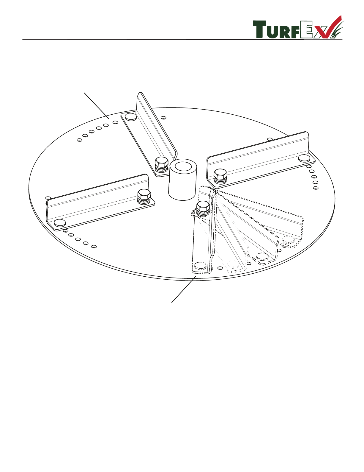
TS-700-E / GR / P & TS-1200-E / GR / P
R
Positions 1 Through 11
Adjustable Fins Shown in
Dierent Positions.
Lift This End Up and
Move To Desired Position.
The purpose of the adjustable n is to provide a way to adjust spread patterns with dierent materials. You can select
the desir
ed position by simply lifting up on the outside top edge. You will notice that dierent materials act in dierent
ways in relation to spinner speed. By moving the ns you will be able to correct most pattern issues without having to
sacrice spinner speed. All adjustments should be made on pavement and positions noted for future reference, this
process should be incorporated into your normal calibration process.
Adjustable Spinner Assembly
1 — 36
© Trynex International 2009 L1302
Page 37
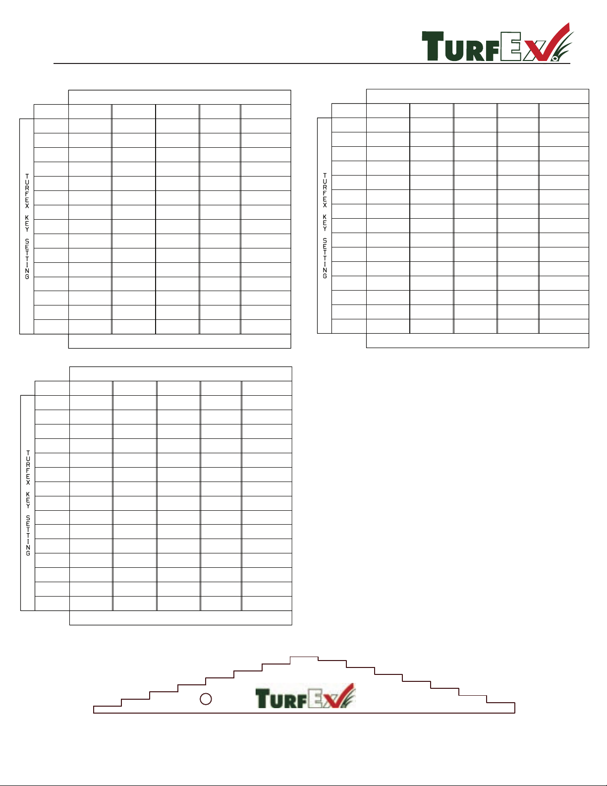
2
3
4
5
6
7
8
9
10
11
12
13
14
15
UREA
46-0-0
GATE
SETTING
15
1.39
X
14
13
12
11
10
9
8
7
6
5
4
3
2
1
LESCO
TURFACE
LESCO
SHADE MIX
LESCO FERT
30-0-10
LESCO
INSECTICIDE
X
X
X
X
X
X
X
X
X
X
X
X
X
X
FLOW RATES ARE CALCULATED AT POUNDS PER MINUTE
TURFEX TS-300-E/EG
7.15
10.54
15.97
24.66
31.36
35.70
47.70
55.29
63.39
73.59
78.60
83.08
93.52
5.28
14.38
18.06
30.24
35.04
50.32
56.22
64.56
76.47
82.59
106.49
122.64
133.72
145.00
0.83
2.11
14.70
37.95
57.32
0.18
0.40
0.51
0.98
0.66
1.78
5.59
7.27
8.72
10.00
11.81
11.94
0.39
3.84
8.79
13.55
17.07
23.94
29.74
39.38
45.20
53.22
64.64
69.06
91.32
0.57
73.80
R
TS - 300-E/EG & TS - 700/ TS -1200 E/GR/P
Calibration Chart
© Trynex International 2009 L1302
1 —
37
UREA
46-0-0
GATE
SETTING
15
3.37
1.18
14
13
12
11
10
9
8
7
6
5
4
3
2
1
LESCO
TURFACE
LESCO
SHADE MIX
LESCO FERT
30-0-10
LESCO
INSECTICIDE
X
X
X
X
X
X
X
X
X
X
.28
.21
1.28
X
FLOW RATES ARE CALCULATED AT POUNDS PER MINUTE
TURFEX TS-700-E/GR/P CALIBRATION DATA
9.37
14.08
23.82
27.61
32.72
41.24
46.16
58.11
70.29
70.95
79.44
87.78
89.43
10.99
20.32
27.52
42.78
47.16
58.48
64.56
85.44
97.52
104.16
105.66
118.56
121.14
140.16
2.59
4.66
15.52
34.40
59.92
1.67
2.14
3.35
7.02
4.02
7.22
8.33
8.68
12.60
12.68
14.19
1.54
7.88
12.89
16.77
19.27
25.34
35.26
40.82
45.81
57.37
62.14
67.29
74.24
3.64
70.48
X
UREA
46-0-0
GATE
SETTING
15
1.39
X
14
13
12
11
10
9
8
7
6
5
4
3
2
1
LESCO
TURFACE
LESCO
SHADE MIX
LESCO FERT
30-0-10
LESCO
INSECTICIDE
X
X
X
X
X
X
X
X
X
X
X
X
X
X
FLOW RATES ARE CALCULATED AT POUNDS PER MINUTE
TURFEX TS-1200-E/GR/P CALIBRATION DATA
7.15
10.54
15.97
24.66
31.36
35.70
47.70
55.29
63.39
73.59
78.60
83.08
93.52
5.28
14.38
18.06
30.24
35.04
50.32
56.22
64.56
76.47
82.59
106.49
122.64
133.72
145.00
0.83
2.11
14.70
37.95
57.32
0.18
0.40
0.51
0.98
0.66
1.78
5.59
7.27
8.72
10.00
11.81
11.94
0.39
3.84
8.79
13.55
17.07
23.94
29.74
39.38
45.20
53.22
64.64
69.06
91.32
0.57
73.80
Calibration Data Is For Reference Only
NOTE:
Page 38

R
300 FEET
10.0
68
136
9.0
8.0
7.0
6.0
5.0
4.5
4.0
3.5
3.0
2.5
2.0
1.5
1.0
.05
272
68
54
45
34
30
27
19
17
15
408
204
192
0.5
45
34
27
23
20
17
15
14
11
9.7
8.5
7.6
6.8
88
132
176
220
264
308
352
136
91
39
23
14
136
82
68
51
58
45
41
34
29
26
23
20
1.0
1.5
2.0
2.5
3.0
3.5
44
100 FEET
GROUND
SPEED IN
MPH
FEET
TRAVELED
PER MIN
GROUND
SPEED
MPH
200 FEET
TIME REQUIRED IN SECONDS TO TRAVEL
A DISTANCE OF
4.0
SPEED-DISTANCE
12.0
5.7
11
17
15.0
4.5
9
13.6
20.0
3.4
6.8
10.2
Calibration Speed-Time-Distance Chart
1 — 38
© Trynex International 2009 L1302
Page 39

CALIBRATION DISCLAIMER
R
It is the responsibilty of the person using this equipment to make sure that every type of
material is properly calibrated to perform as expected. This process should take place on a solid
at surface away from drains and livestock areas in order to achieve a safe and accurate reading
for proper material distribution. Failure to do so may cause an over/under application that could
damage turf areas or give an ineective pest control treatment. Any calibration charts contained in
this manual are given as a refernce point only and should not be used as an absolute condition.
Spending a few extra minutes to properly calibrate will not only save on wasted materials and time
but also protect turf and other vegitation. Below are several points to be aware of before operating
your spreader in the eld.
.
Flow rates of chemicals can change for many reasons
1. Formualtions vary within the same brand or even between brannds
2. Formulations vary between batches or dates of manufacture
3. Humidy can cause the material to clump and ow poorly
4. Poor spreader maintenance can cause ow changes
5. Slide stop has moved or calibrated to another type of material
6. Human error can cause rate miscalculation
.
Items needed for calibriation
1. A way to catch the material for weighing
2. A device to measure distance
3. A scale to weigh your product
4. A stop watch or other means to time
.
Conversion
1. To convert pounds per 1000 square feet to pounds per acre, multiply your rate by 43.6
.
Other important information
1. 1 acre is equal to 43,600 Squre Feet
2. Ground speed is very important to keep in mind when doing calculations, you will want
to convert mph to feet per minute
Set the spreader stop at mid point on it’s travel length as a starting point. Fill the hopper with enough
material to cover a known area of 1000 square feet. Open the gate and make note of the start/stop
time, this is very important. Next weigh the material on a scale, divide the weight by the known area
to establish an application rate. You may have to adjust the gate stop for more or less material
depending on your results.
© Trynex International 2009 L1302
1 — 39
Page 40

R
BLANK PAGE
Blank Page
© Trynex International 2009 L1302
1 —
40
THIS PAGE INTENTIONALY LEFT BLANK
Page 41

R
BLANK PAGE
Blank Page
© Trynex International 2009 L1302
1 —
41
THIS PAGE INTENTIONALY LEFT BLANK
Page 42
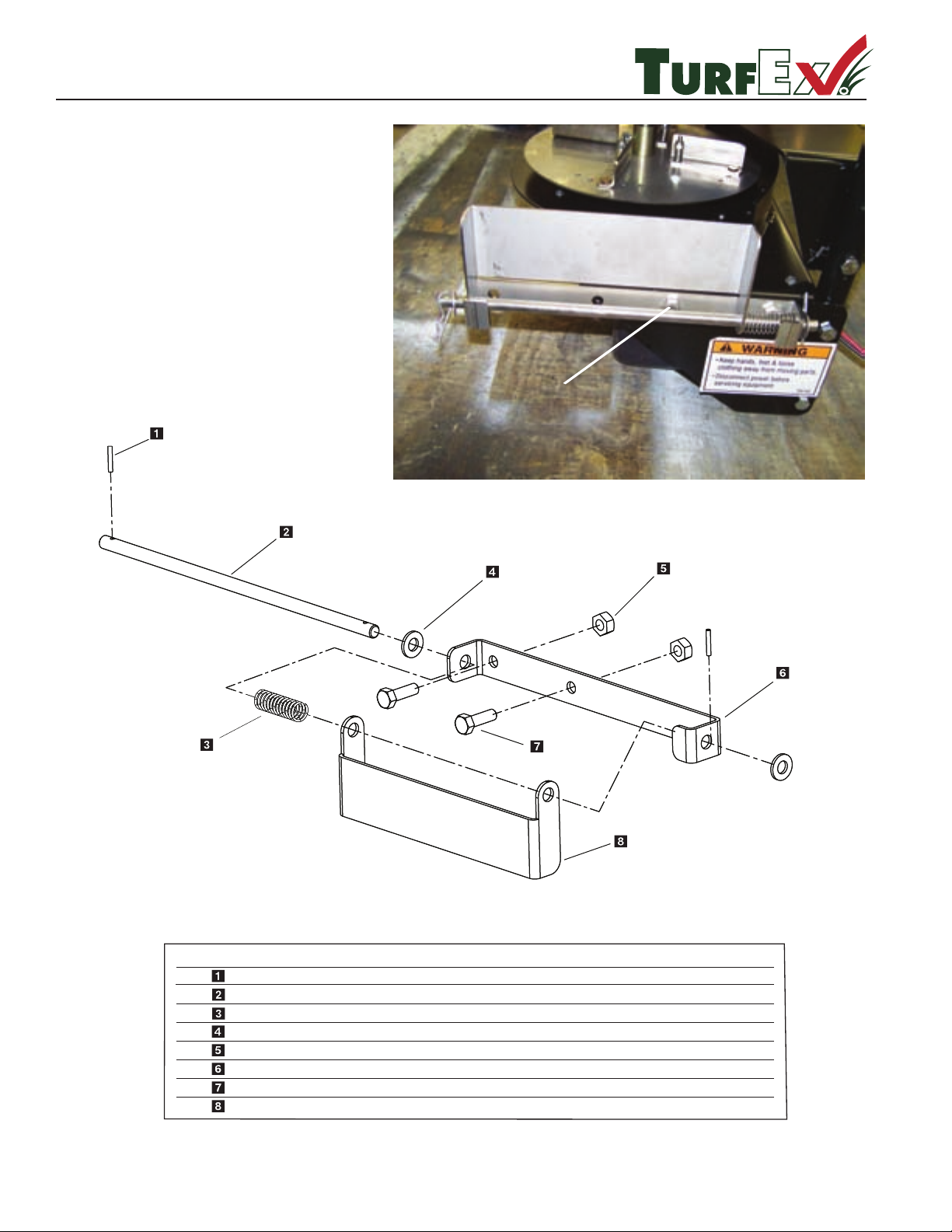
Deector Kit
R
.ytQ noitpircseD .oN traP yeK
1
T-15056 Compression Spring
T-15055 Side Deector Hinge Pin
D - 6853 Cotter Pin
D - 6169 3/8 Flat Washer SS
T-15018 5/16 Nylock Nut SS
T-15054 Deector Mounting Bracket
D - 6418 5/16 - 18 x 1 Hex Bolt ss
T-15053 Side Def;ector
2
2
2
1
1
2
1
Step 1: Mount deector to either right
or left side of spreader as shown
in picture.
Mounting Bolt
Exploded view represents street side
moun
ting conguration
Curb Side Conguration Shown
SDK-020
Parts Breakdown
1 — 42
© Trynex International 2009 L1302
Page 43
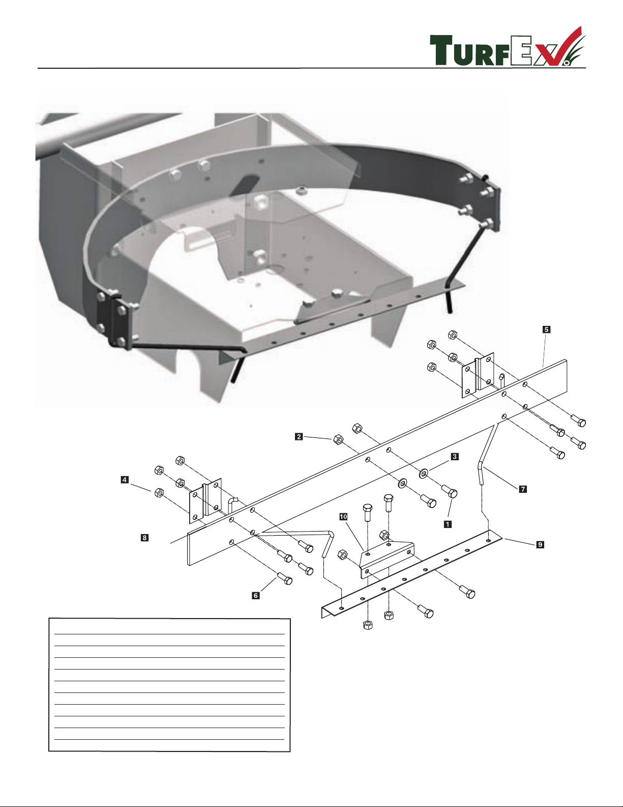
© Trynex International 2009 L1302
1 — 43
R
TS-700-E / P & TS-1200-E / P
ADF-020 Adjustable Deector Kit
.ytQ noitpircseD .oN traP yeK
1 D 4121 3/8'' - 13 x 1'' Hex Bolt
2 D 4124 3/8'' - Locknuts
3 D 4125 3/8'' - Flatwashers
4 D 6138 5/16'' - 18 Locknut
rotcelfeD ''63 4516 D 5
6 D 6166 5/16'' - 18 x 1'' Hex Bolt
7 D 6179 Deector Adjustment Bracket
8 D 6180 Adjustment Bar Mounting Bracket
9 D 6181 Adjustment Bar
2
2
2
10
1
10
1
2
2
T 30222
1
10
Front Adapter Bracket
Page 44
R
TS-300-E / TS-300-EG
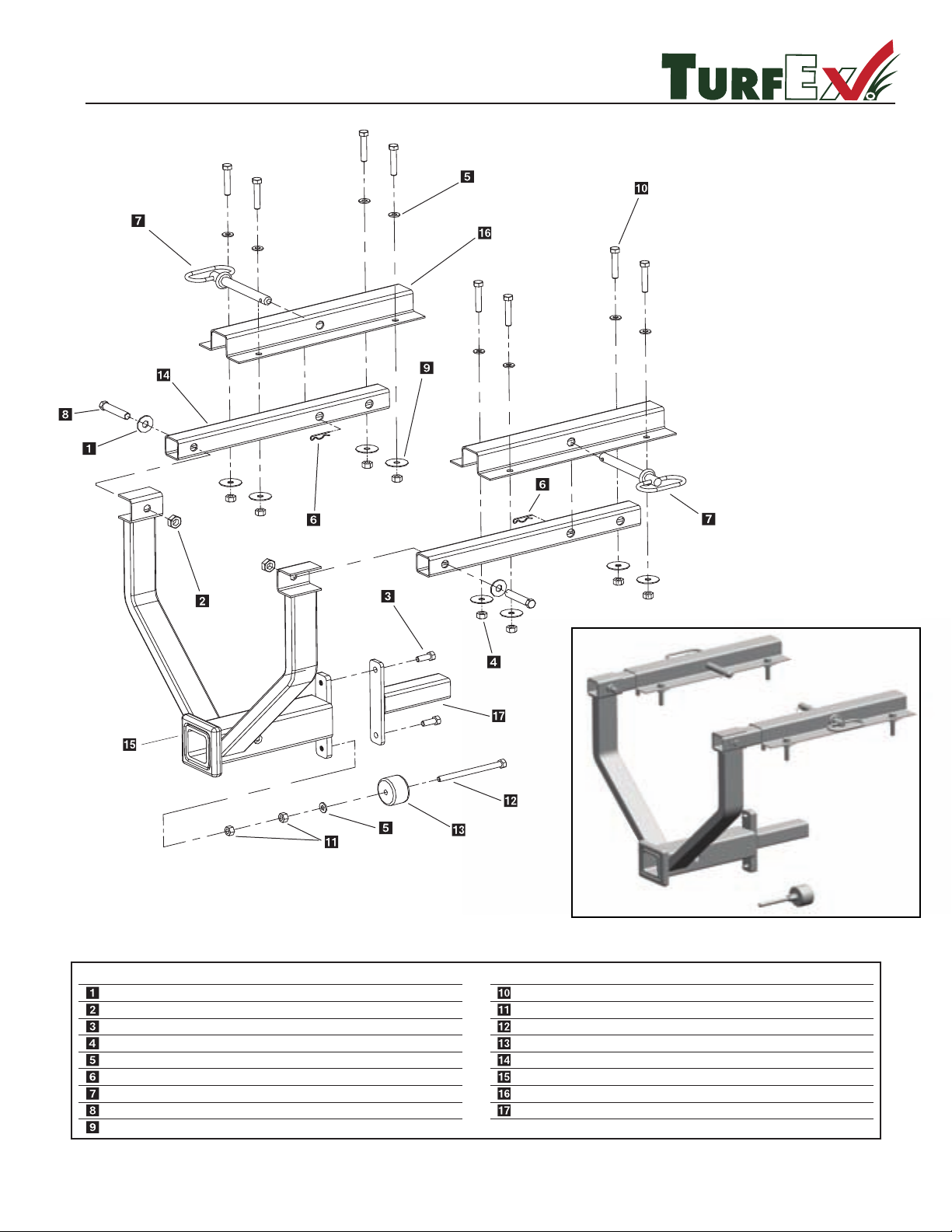
DRM-175 Drop Utility Mount
.ytQ noitpircseD .oN traP yeK
2 rehsaW talF "2/1 9114 D
2 tuN kcoL-"2/1 0214 D
D 4121 3/8"-16x1 Hex Bolt 2
8 tuN kcoL-"8/3 4214 D
9 rehsaW talF "8/3 5214 D
D 4135 2 - 5/16" Hair Pin Clip 2
D 4136 5/8" x 5-1/2" Hitch Pin 2
D 6246 1/2" - 13 x 2-1/2" Hex Bolt 2
D 4318 3/8" Fender Washer 8
.ytQ noitpircseD .oN traP yeK
D 6420 3/8" - 16 x 2 Truss Bolt Full Thread 8
D 6421 3/8" - 16 Hex Nut 2
D 6422 3/8" - 16 x 5" Hex Bolt 1
D 6423 2'' Rubber Stopper 1
2 liaR gnitnuoM 2346 D
D 6434 Drop Mount Weldment 1
D 6435 Mounting Rail Hat Section 2
1 retpadA eluM 6346 D
Maximum Load Weight Not To Exceed 240 lbs. Gross
#3 & #17 Form Stop Type One
#11, 5, 13 & 12 Form Stop Type Two
1 — 44
© Trynex International 2009 L1302
Page 45

DRM-175 Mounting Instructions
R
MULE
550
Step 1:
Step 2: Bolt support rails to spreader mount with 1/2'' bolts. Install 1/2'' hex bolt with washer through rail then spreader
spreader mount. Install 1/2'' locknut and tighten. Avoid over tightening to avoid potentially crushing tube.
Step 3: Place spreader mounting rails over spreader mount support rails and install pins. Locate the spreader bracket mounting rails
on top of the bed by centering left to right and positioning the rear edged of the rails 5/8'' beyond the rear of the bed. Tran sferring
mounting holes to bed & drill 7/16''.
Important: Check for proper clearance underneath bed before drilling holes.
Step 4: Bolt rails under belt with truss head bolts, fender washers, SAE washers and nylon lock nuts. Install the spreader bracket
before tightening hardware. The tailgate and bed liner may be reinstalled now.
Step 5: Install 550 anti dump bracket with (2) 3/8'' bolts provided.
Step 6: Install gate control cable per attached instructions.
Step 7: Route cables at your discretion and install switch.
Temporarily remove the tailgate. Remove the bed liner if equipped.
MULE 2500
The installation of the spreader on the 2500 is the same as the 550 with the following exceptions.
1: When positioning the mounting rails the end of the rails should be 1/2'' forward of the rear edge of the bed.
Step
Step 2: The universal anti dump threads into the lower weld nut on the spreader bracket assembly. Adjust rubber bumper to be 1/2''
to 3/4'' behind the rear axle - receiver hitch assembly.
CLUB CAR CARRYALL
Step 1:
Step 2: Place spreader mounting rails over spreader mount and install pins. Locate the 2 front outside mounting rails over the holes
from the carriage bolts remove in step 1.
Step 3: Install truss head bolts, fender washers, SAE washers and nylon lock nuts in the carriage bolt holes. Transfer the remaining
mounting rail holes and bolt rails into bed.
JOHN DEERE GATOR
Step 1: Remove the bed tailgate.
Step 2: Place spreader mounting rails over spreader mount and install pins.
Step 3: Locate the spreader bracket mounting rails on top of the bed by centering left to right, push main mount up against rear
of bed to locate mounting rails. Transfer mounting holes to bed.
Step 4: Install mounting rails with truss head bolts, fender washers, SAE Washers and nylon lock nuts in the 1/2'' mounting holes.
Step 5: The universal anti dump threads into the lower weld nut on the spreader bracket assembly. The rubber bumper should be
adjusted to rest against the frame of the vehicle. The trailer hitch bracket may need to be relocated depending on
Remove the bed tailgate and bottom angle trim. Also remove the 2 rear carriage bolts from the of the bed.
CAUTION: MAXIMUM WEIGHT NOT TO EXCEED 240 LBS.
ation.
© Trynex International 2009 L1302
1 — 45
Page 46
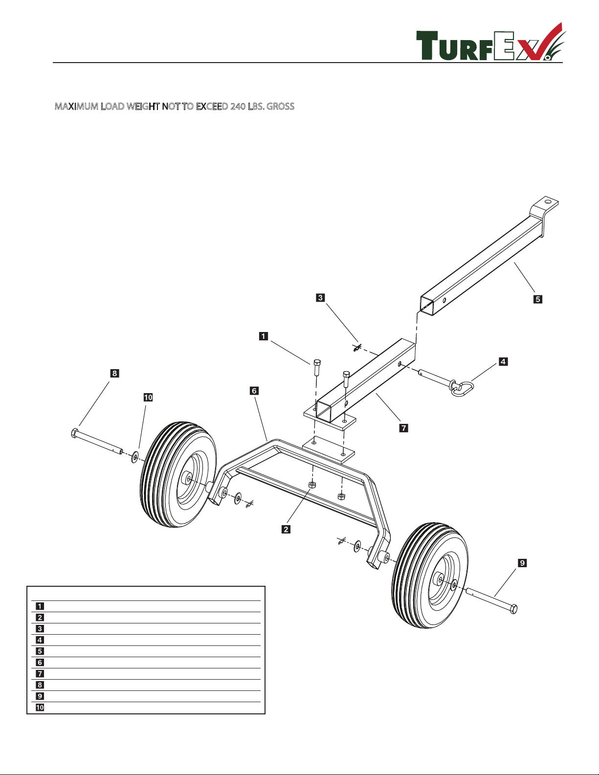
R
Trailer Mount
Model #TLR-175
.ytQ noitpircseD .oN traP yeK
D 4116 1/2'' - 13 x 1-1/2'' Hex bolt 2
2 stunkcoL - ''2/1 0214 D
3 pilc nip riaH 5314 D
D 4136 5/8'' x 5 -1/2'' Hitch pin 1
1 eugnot reliarT 8346 D
1 emarf ”A“ reliarT 9346 D
D 6440 Receive tube mount 1
2 erit reliarT 1446 D
D 6442 5/8'' - 13 x 7'' Hex bolt special 2
D 6443 5/8'' Flat washers 4
MAXIMUM LOAD WEIGHT NOT TO EXCEED 240 LBS. GROSS
TRAILER MOUNT ASSEMBLY INSTRUCTIONS
Step 1: Insert axle through wheel and axle weldment.
Step 2: Put washer on then install hair pin clip to secure axle. Repeat Steps 1 & 2 for other side.
Step 3: Bolt tube support on axle weldment.
Step 4: Insert trailer tongue per drawing and pin into position.
Step 5: Insert spreader mount into opposite side of trailer tongue and pin into position.
© Trynex International 2009 L1302
1 —
46
Page 47
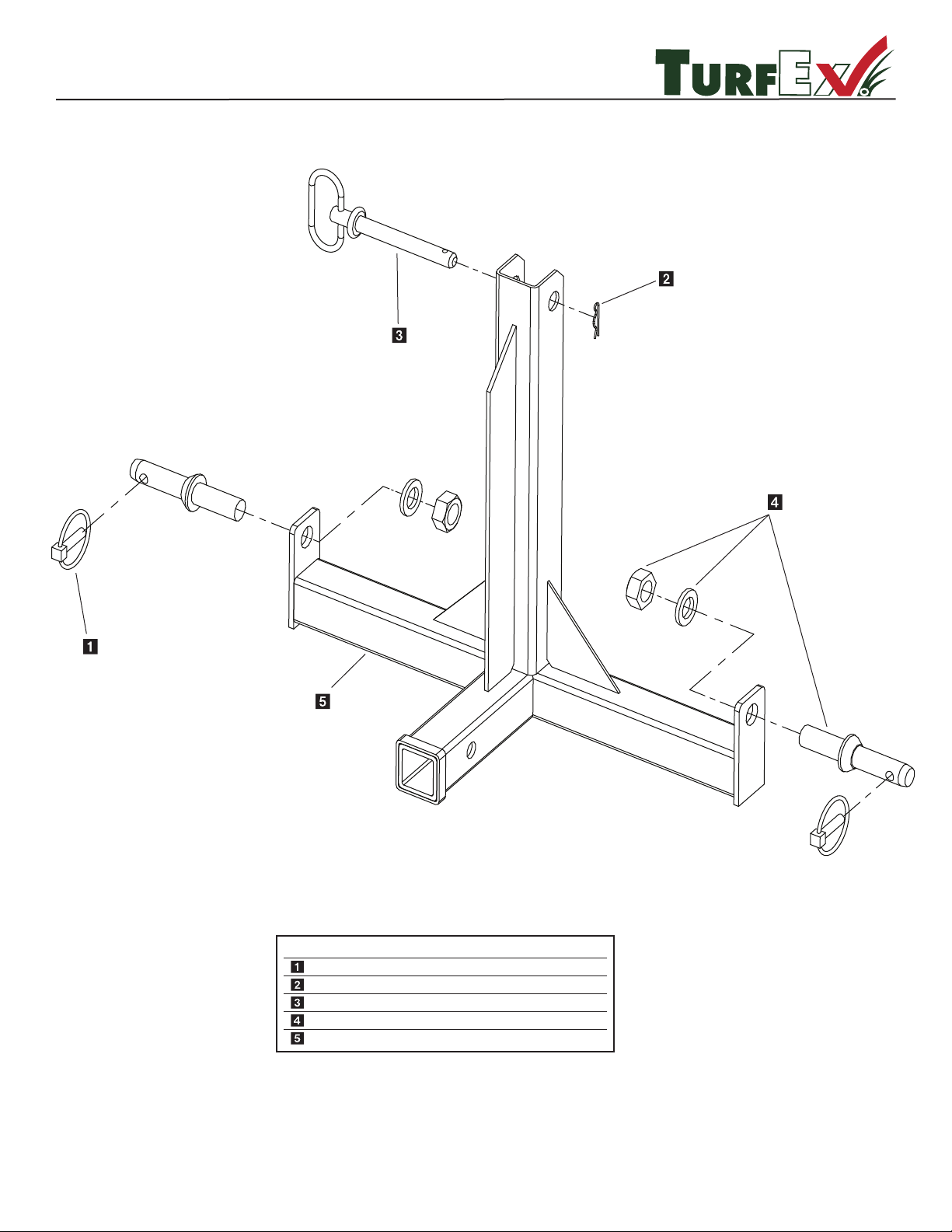
R
3-Point Mount
Model #TPM-175
CAUTION: MAXIMUM OF 240 LBS. GROSS WEIGHT CAN BE PUT ONTO MOUNT.
Key Part No. Description Qty.
D 4133 5/16” Linch Pin 2
D 4135 2-5/16” Hairpin Clip 1
D 4136 5/8” x 5-1/2” Hitch Pin 1
D 4137 7/8” x 5-1/2” Lift Arm Pin 2
D 6147 3-Point Frame 1
© Trynex International 2009 L1302
1 — 47
Page 48
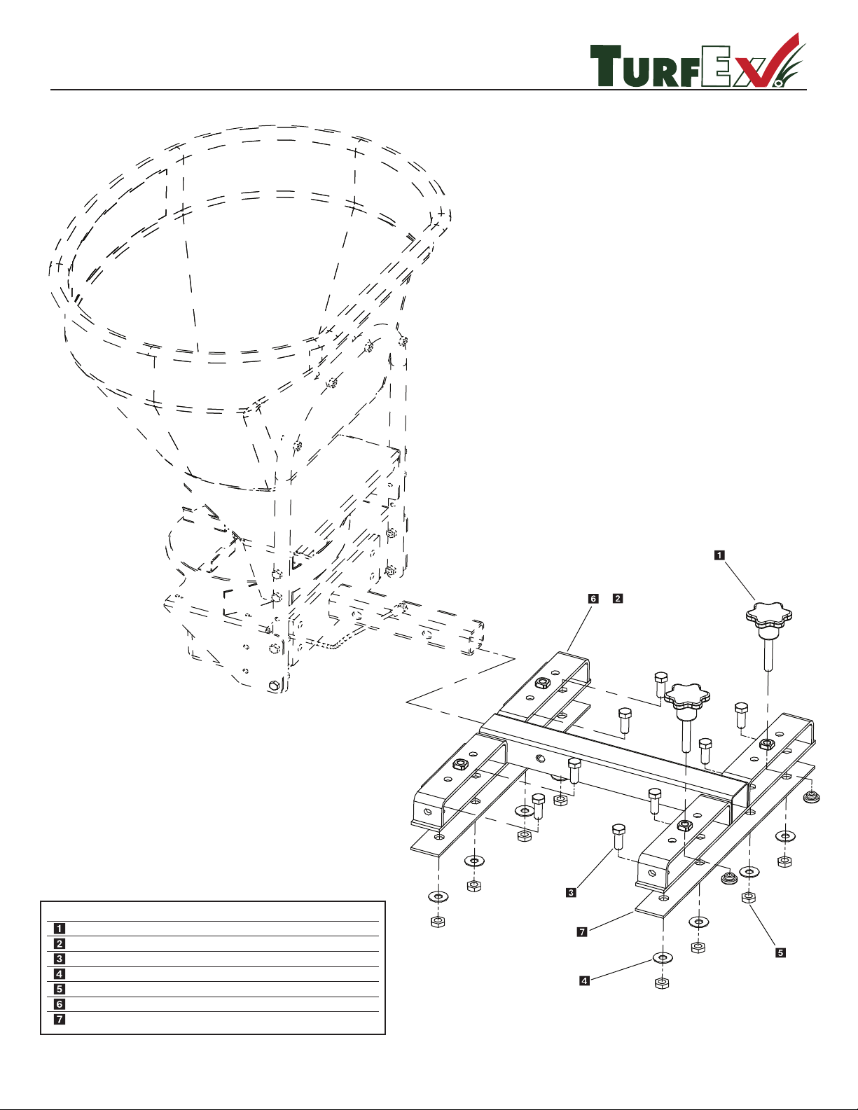
R
Utility Mount
Model #UTM/FLM-175
Spreader
(reference only)
Maximum Load Weight
Not To Exceed 240 lbs. Gross
.ytQ noitpircseD .oN traP yeK
D 4315 Lock Knob Assembly (FLM-175 Only) 2
D 6426 Fork Lift Mount Frame (FLM) 1
D 4116 1/2"-13 x 1 1/2" Hex Bolt 8
8 rehsaW talF "2/1 9114 D
8 tuN kcoL "2/1 0214 D
1
r (UTM)evieceR ytilitU
8416 D
D 6235 Underbody Support Plate 2
&
© Trynex International 2009 L13021 — 48
Page 49
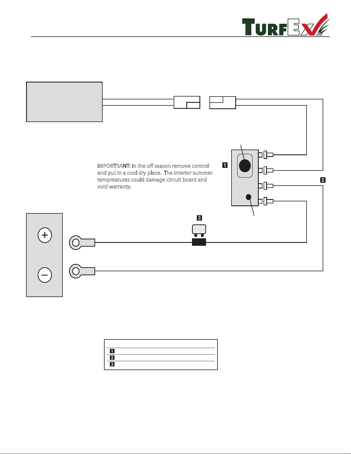
VAR-020 ACCEESORY CONTROL KIT
R
TS-300 (Optional Kit)
SPREADER MOTOR
(–) Neg. Black
(+) Pos.Red
IMPORTRANT: In the o season remove control
and put in a cool dry place. The interior summer
tempreatures could damage circuit board and
void warranty.
Speed Control Knob
12 VOLT
BATTERY
20 AMP
(+) Pos.Red
(–) Neg. Black
Key Part No. Description Qty.
D 7171 Mini Control 1
D 6719 Harness 1
D 6482 20 Amp Breaker 1
On/O Switch
© Trynex International 2009 L1302
1 — 49
Page 50
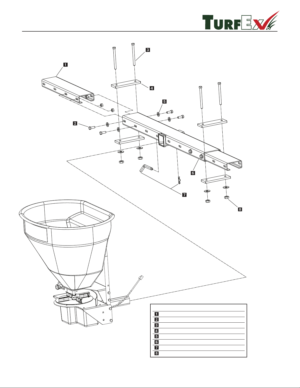
TS-300 / TS-300-EG
R
SPREADER SHOWN FOR
REFERENCE PURPOSES ONLY
Key
T 15040
3/8-16 x 1-1/2 Hex Head
Side Extension
3/8-16 x 5 Full Thread HHCS
Tie Down Bracket
3/8 Flat Washer
Main Mount Weldment
Hitch Pin
3/8-16 Nylock
D 4122
T 30206
T 15042
D 4125
T 15041
T 15043
D 4124
2
8
4
4
12
1
1
12
Part No.
D
escription Qty.
ZTR-020
© Trynex International 2009 L13021 — 50
Page 51

Spreader Maintenance
R
t Store controller in safe dry spot during the o season.
t WARNING – When servicing is necessary, perform it in a protected area. Do not use power tools in rain or snow because of
DANGER of electrical shock or injury. Keep area well lighted. Use proper tools. Keep the area of service clean to help avoid
accidents.
t WARNING – Disconnect electricity to spreader before servicing.
t CAUTION – The controller is a solid state electronic unit and is not serviceable. Any attempt to service will void warranty.
t CAUTION – There are no serviceable parts in the motor/transmission assembly. Any attempt to service will void warranty.
t CAUTION – When replacing parts use only original manufacturer’s parts. Failure to do so will void warranty.
t Use diaelectric grease on all electrical connections to prevent corrosion at the beginning and end of the season and each
Time plugs are disconnected.
t Gently wash unit after each use to prevent material build-up and corrosion.
t CAUTION – When pressure washing motor enclosure area stay at least 36'' away from all electrical items.
t Paint or oil all bare metal surfaces at the end of the season.
t Keep gate cable lubricated with a graphite type lubricant (non-tacky) after each use.
t If motor cover is removed for any reason, use silicone sealant to ensure weather proong of enclosure.
t Grease bearings after every 20 hours use.
t After rst use, tighten all nuts and bolts on spreader and mount.
t WARNING: Never remove spreader with material in hopper.
© Trynex International 2009 L1302
1 — 51
Page 52
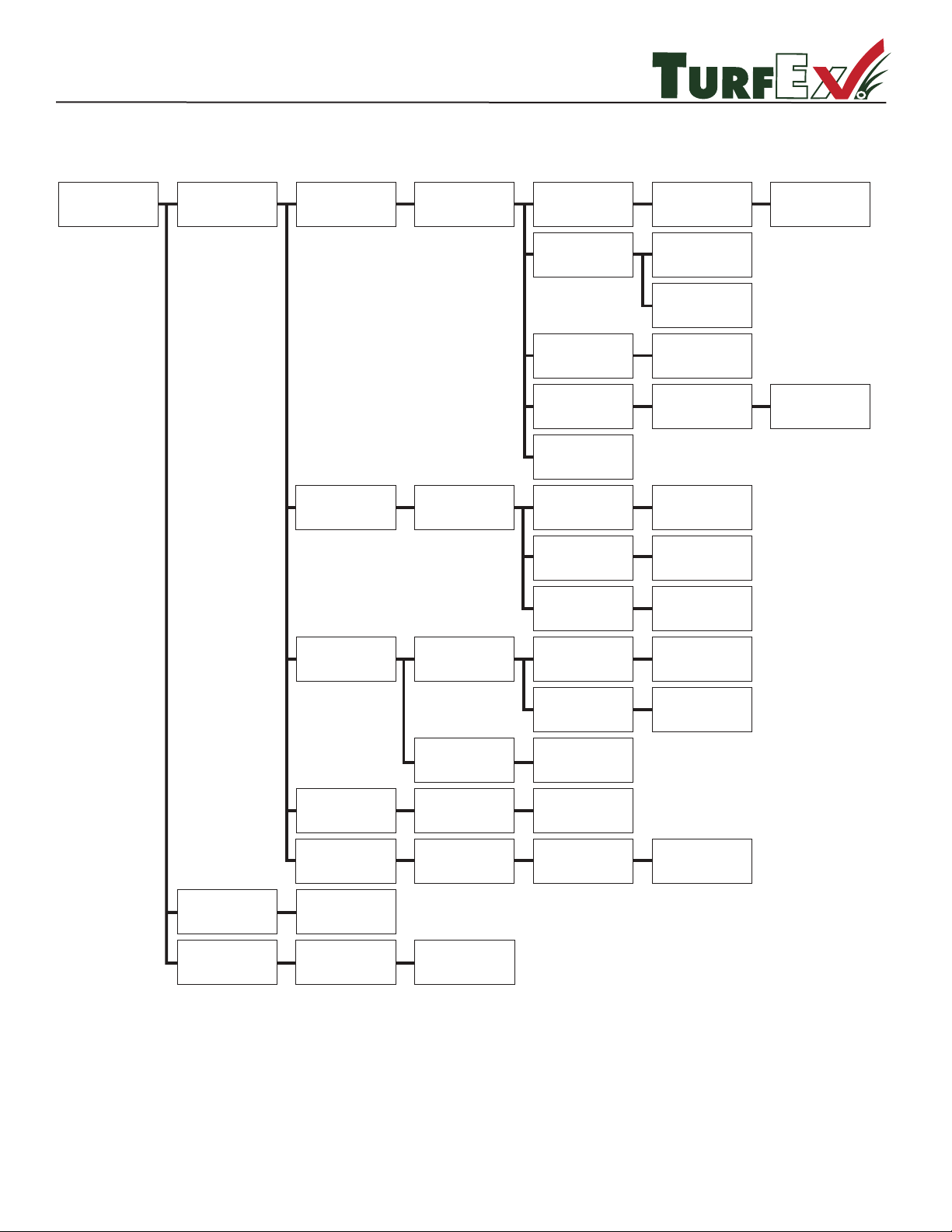
R
Troubleshooting
TS-300 / TS-300-EG / TS-700-E / TS-1200-E
SPREADER
DOES NOT RUN
CONTROLLER TURNS ON
BEEP SHUTS OFF
DISPLAYS ERROR CODE
OL CODE
EO CODE
DEFINITION:
AMP DRAW
TOO HIGH
DEFINITION:
OPEN CIRCUIT BETWEEN
MOTOR AND CONTROLLER
JAMMED MATERIAL
BAD MOTOR
CHECK WITH TEST KIT
BAD TRANSMISSION
CORROSION
BAD CONTROLLER
CHECK WITH TEST KIT
SPREADER UNPLUGGED
MOTOR POWER CORD
DISCONNECTED
INSIDE DRIVE ASSEMBLY
BREAK IN
WIRING HARNESS
CHECK WITH TEST KIT
SWITCH OFF & ON
FOR AUTO-REVERSE
FUNCTION
TEST 4 TO 20 AMP DRAW
NO LOAD GOOD
20+ AMP DRAW
NO LOAD BAD
TEST TURN SHAFT
BY HAND
SHOULD TURN FREELY
REPLACE ALL
CORRODED
CONNECTIONS
PLUG IN SPREADER
OPEN ACCESS COVER
AND PLUG TOGETHER
REPLACE HARNESS
CLEAR JAM
DON'T FORGET
USE DIELECTRIC
GREASE
LB CODE
E1 CODE
ALL OTHER
ON/OFF SWITCH
LIGHTS NO DISPLAY
NOTHING HAPPENS
NO DISPLAY
ON/OFF SWITCH WILL
NOT LIGHT UP
CODES
BAD CONTROLLER
CHECK WITH TEST KIT
CHECK POWER SOURCE
TO CONTROLLER
BAD ELECTRICAL
CONNECTION
LOW BATTERY
LESS THAN 12 VOLT
OUTPUT
DEAD SHORT
IN MOTOR CIRCUIT
CHECK HARNESS
FOR SPLICED IN
ACCESSORY
BAD CONTROLLER
CHECK WITH TEST KIT
CORROSION
LOOSE CONNECTION
LOAD TEST BATTERY
REPLACE
AFFECTED
COMPONENTS
BAD CONTROLLER
CHECK WITH TEST KIT
REPLACE ALL CORRODED
CONNECTIONS
TIGHTEN OR REPLACE
REPLACE
© Trynex International 2009 L13021 — 52
Page 53
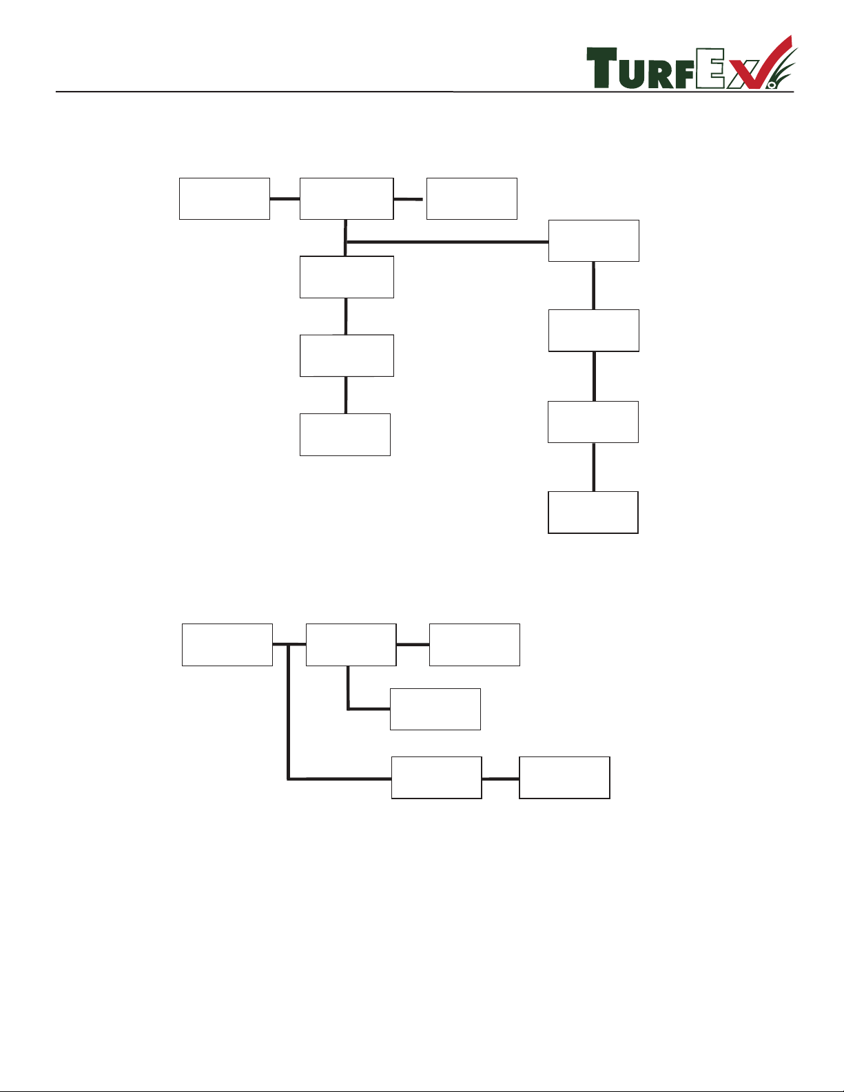
R
Troubleshooting (continued)
MATERIAL
FREE FLOWS
GATE OPEN
SHUT GATE
REPLACE
CABLE FROZEN
LUBRICATE
MATERIAL
WILL NOT FLOW
GATE
CLOSED
OPEN
GATE
OBSTRUCTION
REMOVE
LINKAGE FROZEN
REMOVE AND CLEAN
LUBRICATE
REPLACE
SEE ABOVE FOR
FROZEN PARTS
© Trynex International 2009 L1302
1 — 53
Page 54
Warranty
Limited Warranty
Two year warranty on Turfex brand products against defects in material or workmanship
under normal use and service, subject to limitations detailed below. Warranty period of
two years begins on the date of purchase by the original retail user.
The WARRANTY REGISTRATION CARD must be returned to the manufacturer for this warranty
to become eective. This warranty applies to the original retail purchaser only. This warranty does
not cover damages caused by improper installation, misuse, lack of proper maintenance, alterations
or repairs made by anyone other than authorized Trynex dealers or Trynex personnel. Due to the
corrosive properties of the materials dispensed by spreaders, Trynex does not warrant against
damage caused by corrosion. Warranty claims by the user must be made to the dealer from where
the product was purchased, unless otherwise authorized by Trynex. Trynex reserves the right to
determine if any part is defective and to repair or replace such parts as it elects. This warranty does
not cover shipping costs of defective parts to or from the dealer.
LIMITATION OF LIABILITY
Neither Trynex, nor any company aliated with it, makes any warranties, representations for
promise as to the performance or quality other that what is herein contained. The liability of Trynex
to the purchaser for damages arising out of the manufacture, sale, delivery, use or resale of this
spreader shall be limited to and shall not exceed the costs of repair or replacement of defective
parts. Trynex shall not be liable for loss of use, inconvenience or any other incidental, indirect or
consequential damages, so the above limitations on incidental or consequential damages may not
apply to you.
NO DEALER HAS AUTHORITY TO MAKE ANY REPRESENTATION OR PROMISE ON BEHALF OF
TRYNEX INTERNATIONAL, OR TO ALTER OR MODIFY THE TERMS OR LIMITATIONS OF THIS
WARRANTY IN ANY WAY.
R
1 — 54
© Trynex International 2009 L1302
Page 55

Warranty Registration and Customer Survey
Very
Satised
Very
Dissatised
Satised Dissatised
Somewhat
Satised
Somewhat
Dissatised
Very
Satised
Very
Dissatised
Satised Dissatised
Somewhat
Satised
Somewhat
Dissatised
PLEASE FOLD AND SEAL WITH TRANSPARENT TAPE BEFORE MAILING.
R
To initiate the warranty on your new TurfEx product and assure prompt warranty service, please complete the
following warranty registration and customer survey, sign and mail it back to the factory within 30 days of purchase.
1) Date of Purchase:
2) Name:
Address:
Phone:
:rebmuN laireS:desahcruP ledoM Turfex)3
4) Is this your rst Turfex Product?
5) What type of vehicle are you using with your Spreader, Broom and/or Sprayer?
6) What type of material are you using in your spreader and/or sprayer?
7) TurfEx Dealer Name:
TurfEx Dealer Address:
Turfex Dealer Phone:
8) Does your TurfEx Dealer stock Turf Ex replacement Parts? Yes No I don’t know
9) Do you feel your TurfEx Dealer sold you the correct product for your needs/application? Yes No
10) How would you rate
your overall satisfaction
with your Turfex Dealer?-
11) How would you rate
your overall satisfaction
with your Turfex Product?
Yes No
raeYledoMekaM
12) Would you purchase another TurfEx Product?
13)
If you would like to receive E-Mail ALERTS for new products, bulletins or special promotions please supply address : _________________________________________________
14) Please use the space below to convey your comments and/or suggestions.
NOTE: I have read the owner’s manual and all safety precautions and I understand that this equipment could be dangerous if not operated
with care and under the proper conditions.
15) Owner’s signature:
X
Yes No
© Trynex International 2009 L1302
1 —55
Page 56

Simply Fill Out Your
Warranty Registration and
Return It to the Factory!
From:
Postage
Required
Post Oce will
not deliver
without proper
postage.
23455 REGENCY PARK DR.
WARREN MI 48089-2667
 Loading...